Transmission and Transfer Case — part 1 of 6 — 1998 Jeep Grand Cherokee ZJ Export Service Manual
Pages 1369–1428 · 60 pages · 11 words repaired
OVERDRIVE PISTON RETAINER . . . . . . . . . . 63 PLANETARY GEARTRAIN/OUTPUT SHAFT . . . . 71 REAR CLUTCH . . . . . . . . . . . . . . . . . . . . . . . . . 70 REAR SERVO PISTON . . . . . . . . . . . . . . . . . . . . 65 TRANSMISSION . . . . . . . . . . . . . . . . . . . . . . . . . 53 VALVE Body . . . . . . . . . . . . . . . . . . . . . . . . . . . 39 CLEANING AND INSPECTION
ACCUMULATOR . . . . . . . . . . . . . . . . . . . . . . . . . 92 FRONT CLUTCH . . . . . . . . . . . . . . . . . . . . . . . . 93 FRONT SERVO . . . . . . . . . . . . . . . . . . . . . . . . . 93 OIL PUMP AND REACTION
SHAFT SUPPORT . . . . . . . . . . . . . . . . . . . . . . 93 OVERDRIVE UNIT . . . . . . . . . . . . . . . . . . . . . . . 95 OVERRUNNING CLUTCH/LOW-REVERSE
DRUM/OVERDRIVE PISTON RETAINER . . . . . 92 PLANETARY GEARTRAIN . . . . . . . . . . . . . . . . . 94
GENERAL INFORMATION
42/44 RE TRANSMISSION
The 42/44RE is a four speed fully automatic transmission (Fig. 1) with an electronic governor. First through third gear ranges are provided by the clutches, bands, overrunning clutch, and planetary gear sets in the transmission. Fourth gear range is provided by the overdrive unit that contains an overdrive clutch, direct clutch, planetary gear set, and overrunning clutch. The overdrive clutch is applied in fourth gear only. The direct clutch is applied in all ranges except fourth gear. The torque converter
BAND ADJUSTMENTS . . . . . . . . . . . . . . . . . . . . 98 BRAKE TRANSMISSION SHIFT INTERLOCK . . . 95 GEARSHIFT CABLE . . . . . . . . . . . . . . . . . . . . . . 97 TRANSMISSION THROTTLE VALVE CABLE
ADJUSTMENT . . . . . . . . . . . . . . . . . . . . . . . . . 96 VALVE Body . . . . . . . . . . . . . . . . . . . . . . . . . . . 98 SCHEMATICS AND DIAGRAMS
HYDRAULIC SCHEMATICS . . . . . . . . . . . . . . . . 99 SPECIFICATIONS
TRANSMISSION . . . . . . . . . . . . . . . . . . . . . . . . 112 SPECIAL TOOLS
RE TRANSMISSIONS . . . . . . . . . . . . . . . . . . . . 112 clutch is controlled by the Powertrain Control Module (PCM). The torque converter clutch is hydraulically applied and is released when fluid is vented from the hydraulic circuit by the torque converter control (TCC) solenoid on the valve body. The torque converter clutch engages in fourth gear, and in third gear when the O/D switch is OFF. Engagement occurs when the vehicle is moving at a steady speed after the vehicle has warmed up. The torque converter clutch disengages when the accelerator is applied. The 42/44 RE transmission is cooled by an integral fluid cooler inside the radiator.
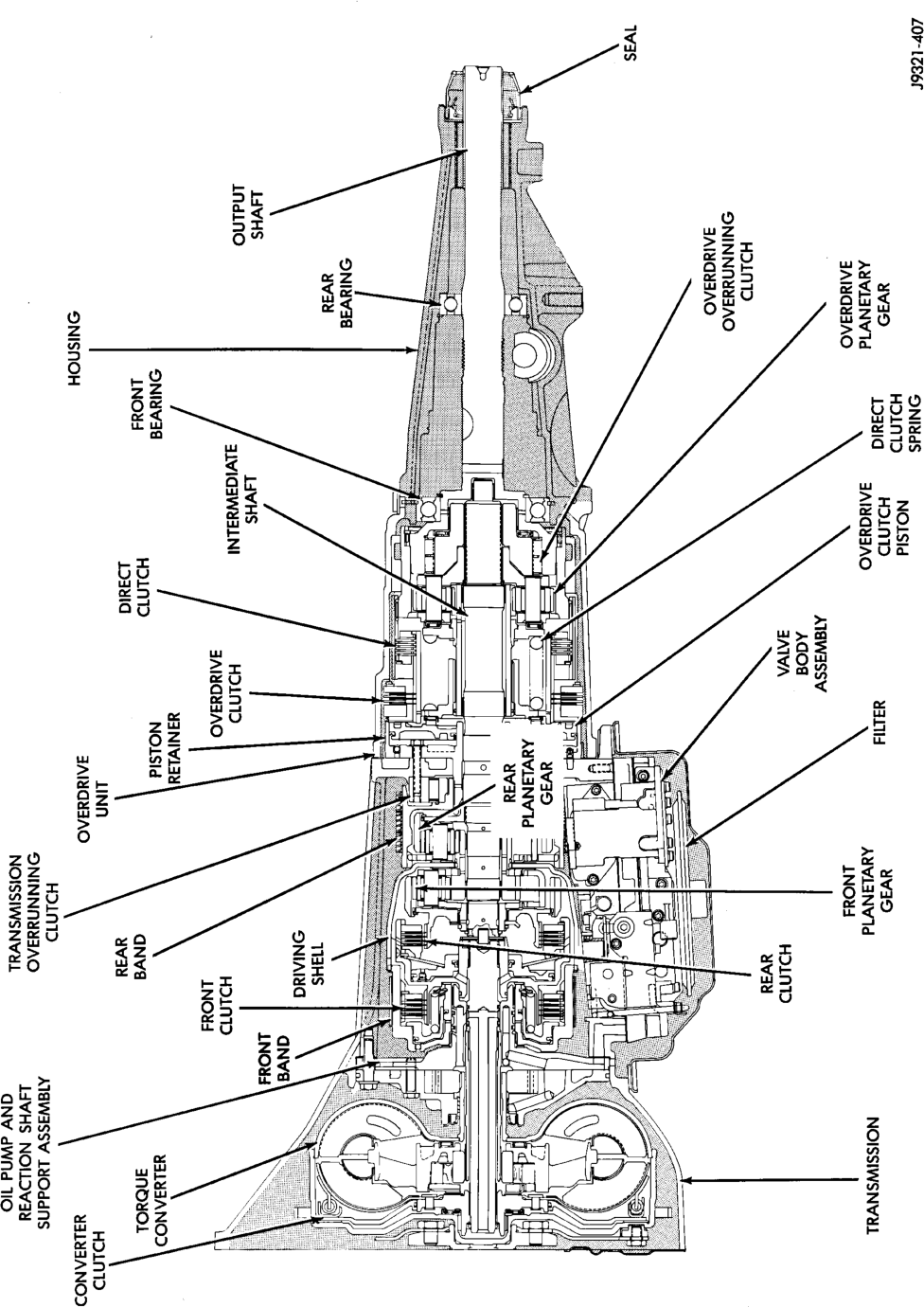

TRANSMISSION IDENTIFICATION
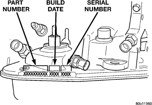
Transmission identification numbers are stamped on the left side of the case just above the oil pan gasket surface (Fig. 2). Refer to this information when ordering replacement parts.
Location
RECOMMENDED FLUID
Mopart ATF Plus 3, Type 7176 automatic transmission fluid is the recommended fluid for Chrysler automatic transmissions.
Dexron II fluid IS NOT recommended. Clutch chatter can result from the use of improper fluid.
EFFECTS OF INCORRECT FLUID LEVEL
A low fluid level allows the pump to take in air along with the fluid. Air in the fluid will cause fluid pressures to be low and develop slower than normal. If the transmission is overfilled, the gears churn the fluid into foam. This aerates the fluid and causing the same conditions occurring with a low level. In either case, air bubbles cause fluid overheating, oxidation and varnish buildup which interferes with valve, clutch and servo operation. Foaming also causes fluid expansion which can result in fluid overflow from the transmission vent or fill tube. Fluid overflow can easily be mistaken for a leak if inspection is not careful.
CAUSES OF BURNT FLUID
Burnt, discolored fluid is a result of overheating which has two primary causes.
(1) A result of restricted fluid flow through the main and/or auxiliary cooler. This condition is usually the result of a faulty or improperly installed drainback valve, a damaged main cooler, or severe restrictions in the coolers and lines caused by debris or kinked lines.
(2) Heavy duty operation with a vehicle not properly equipped for this type of operation. Trailer towing or similar high load operation will overheat the transmission fluid if the vehicle is improperly equipped. Such vehicles should have an auxiliary transmission fluid cooler, a heavy duty cooling system, and the engine/axle ratio combination needed to handle heavy loads.
FLUID CONTAMINATION Transmission fluid contamination is generally a result of:
• adding incorrect fluid • failure to clean dipstick and fill tube when checking level
• engine coolant entering the fluid • internal failure that generates debris • overheat that generates sludge (fluid breakdown)
• failure to reverse flush cooler and lines after repair
• failure to replace contaminated converter after repair
The use of non recommended fluids can result in transmission failure. The usual results are erratic shifts, slippage, abnormal wear and eventual failure due to fluid breakdown and sludge formation. Avoid this condition by using recommended fluids only.
The dipstick cap and fill tube should be wiped clean before checking fluid level. Dirt, grease and other foreign material on the cap and tube could fall into the tube if not removed beforehand. Take the time to wipe the cap and tube clean before withdrawing the dipstick. Engine coolant in the transmission fluid is generally caused by a cooler malfunction. The only remedy is to replace the radiator as the cooler in the radiator is not a serviceable part. If coolant has circulated through the transmission for some time, an overhaul may also be necessary; especially if shift problems had developed.
The transmission cooler and lines should be reverse flushed whenever a malfunction generates sludge and/or debris. The torque converter should also be replaced at the same time.
Failure to flush the cooler and lines will result in recontamination. Flushing applies to auxiliary coolers as well. The torque converter should also be replaced whenever a failure generates sludge and debris. This is necessary because normal converter flushing procedures will not remove all contaminants.
ELECTRONIC LOCK-UP TORQUE CONVERTER
The torque converter is a hydraulic device that couples the engine crankshaft to the transmission.
The torque converter consists of an outer shell with an internal turbine, a stator, an overrunning clutch, an impeller, and an electronically applied converter clutch. Torque multiplication is created when the stator directs the hydraulic flow from the turbine to rotate the impeller in the direction the engine crankshaft is turning. The turbine transfers power to the planetary gear sets in the transmission. The transfer of power into the impeller assists torque multiplication. At low vehicle-speed, the overrunning clutch holds the stator stationary (during torque multiplication) and allows the stator to freewheel at high vehicle speed. The converter clutch engagement reduces engine speed. Clutch engagement also provides reduced transmission fluid temperatures. The torque converter hub drives the transmission oil (fluid) pump.
The torque converter is a sealed, welded unit that is not repairable and is serviced as an assembly.
CAUTION: The torque converter must be replaced if a transmission failure results in large amounts of metal or fiber contamination in the fluid.
TRANSMISSION GEAR RATIOS
Gear ratios are: • 1st 2.74:1 • 2nd 1.54:1 • 3rd 1.00:1 • 4th 0.69:1 • Rev. 2.21
GEARSHIFT MECHANISM
The shift mechanism is cable operated and provides six shift positions. The shift positions are:
• Park (P) • Reverse (R) • Neutral (N) • Drive (D) • Manual Second (2) • Manual Low (1) Manual low (1) range provides first gear only. Overrun braking is also provided in this range. Manual second (2) range provides first and second gear only. Drive range provides first, second, third, and overdrive fourth gear ranges. The shift into overdrive fourth gear range occurs only after the transmission has completed the shift into (D) third gear range. No further movement of the shift mechanism is required to complete the 3-4 shift.
DESCRIPTION AND OPERATION
ELECTRONIC GOVERNOR
Governor pressure is controlled electronically. Components used for governor pressure control include:
• Governor body • Valve body transfer plate • Governor pressure solenoid valve • Governor pressure sensor • Fluid temperature thermistor • Throttle position sensor (TPS) • Transmission speed sensor • Powertrain control module (PCM)
GOVERNOR PRESSURE SOLENOID VALVE
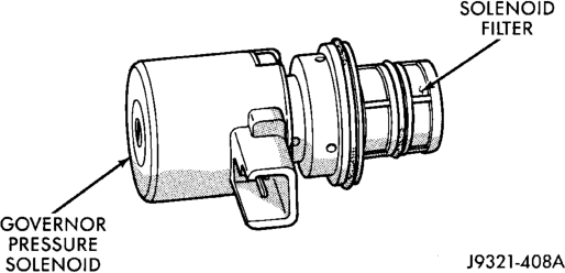
The solenoid valve is a duty-cycle solenoid which regulates the governor pressure needed for upshifts and downshifts. It is an electro-hydraulic device located in the governor body on the valve body transfer plate (Fig. 3).
The inlet side of the solenoid valve is exposed to normal transmission line pressure. The outlet side of the valve leads to the valve body governor circuit.
The solenoid valve regulates line pressure to produce governor pressure. The average current supplied to the solenoid controls governor pressure. One amp current produces zero kPa/psi governor pressure. Zero amps sets the maximum governor pressure.
The powertrain control module (PCM) turns on the trans control relay which supplies electrical power to the solenoid valve. Operating voltage is 12 volts (DC). The PCM controls the ground side of the solenoid using the governor pressure solenoid control circuit.
GOVERNOR PRESSURE SENSOR
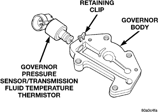
The governor pressure sensor measures output pressure of the governor pressure solenoid valve (Fig. 4).
The sensor output signal provides the necessary feedback to the PCM. This feedback is needed to adequately control governor pressure.
GOVERNOR BODY AND TRANSFER PLATE
The transfer plate is designed to supply transmission line pressure to the governor pressure solenoid valve and to return governor pressure.
The governor pressure solenoid valve is mounted in the governor body. The body is bolted to the lower side of the transfer plate (Fig. 4). The transfer plate channels line pressure to the solenoid valve through the governor body. It also channels governor pressure from the solenoid valve to the governor circuit. It is the solenoid valve that develops the necessary governor pressure.
TRANSMISSION FLUID TEMPERATURE
THERMISTOR
Transmission fluid temperature readings are supplied to the transmission control module by the thermistor. The temperature readings are used to control engagement of the fourth gear overdrive clutch, the converter clutch, and governor pressure. Normal resistance value for the thermistor at room temperature is approximately 1000 ohms.
The PCM prevents engagement of the converter clutch and overdrive clutch, when fluid temperature is below approximately 10°C (50°F). If fluid temperature exceeds 126°C (260°F), the PCM causes a 4-3 downshift and engage the converter clutch. Engagement is according to the third gear converter clutch engagement schedule.
The overdrive OFF lamp in the instrument panel illuminates when the shift back to third occurs. The transmission will not allow fourth gear operation until fluid temperature decreases to approximately 110°C (230°F).
The thermistor is part of the governor pressure sensor assembly and is immersed in transmission fluid at all times.
TRANSMISSION SPEED SENSOR
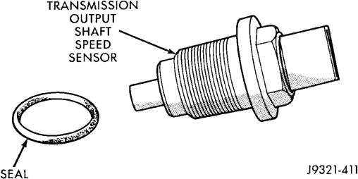
The speed sensor (Fig. 5) is located in the overdrive gear case. The sensor is positioned over the park gear and monitors transmission output shaft rotating speed. Speed sensor signals are triggered by the park gear lugs as they rotate past the sensor pickup face. Input signals from the sensor are sent to the transmission control module for processing. The vehicle speed sensor also serves as a backup for the transmission speed sensor. Signals from this sensor are shared with the powertrain control module.
THROTTLE POSITION SENSOR (TPS)
The TPS provides throttle position input signals to the PCM. This input signal is used to determine overdrive and converter clutch shift schedule and to select the proper governor curve.
POWERTRAIN CONTROL MODULE (PCM)
The PCM controls operation of the converter clutch, overdrive clutch, and governor pressure solenoid.
The control module determines transmission shift points based on input signals from the transmission thermistor, transmission output shaft speed sensor, crankshaft position sensor, vehicle speed sensor, throttle position sensor, and battery temperature sensor.
GOVERNOR PRESSURE CURVES
There are four governor pressure curves programmed into the transmission control module. The different curves allow the control module to adjust governor pressure for varying conditions. One curve is used for operation when fluid temperature is at, or below, 1°C (30°F). A second curve is used when fluid temperature is at, or above, 10°C (50°F) during normal city or highway driving. A third curve is used during wide-open throttle operation. The fourth curve is used when driving with the transfer case in low range.
SHIFT VALVE OPERATION
The shift valves are moved by a combination of throttle and governor pressure. The governor pressure is generated by electrical components.
The conditions under which a shift to fourth will not occur are:
• Overdrive switch is Off • Transmission fluid temperature is below 10° C (50° F) or above 121° C (250° F)
• Shift to third not yet completed • Vehicle speed too low for 3-4 shift to occur • Battery temperature below –5° F.
HYDRAULIC CONTROL SYSTEM
The hydraulic control system provides fully automatic operation. The system performs five basic functions which are: pressure supply, pressure regulation, flow control, clutch/band application, and lubrication.
PRESSURE REGULATION
The pressure regulator valve maintains line pressure. The amount of pressure developed is controlled by throttle pressure which is dependent on the degree of throttle opening. The regulator valve is located in the valve body.
The throttle valve determines line pressure and shift speed. Governor pressure increases in proportion to vehicle speed. The throttle valve controls upshift and downshift speeds by regulating pressure according to throttle position.
Shift Vaive Flow Control
The manual valve is operated by the gearshift linkage and provides the operating range selected by the driver.
The 1-2 shift valve provides 1-2 or 2-1 shifts and the 2-3 shift valve provides 2-3 or 3-2 shifts.
The kickdown valve provides forced 3-2 or 3-1 downshifts depending on vehicle speed. Downshifts occur when the throttle is opened beyond downshift detent position. Detent is reached just before wide open throttle position.
The 2-3 valve throttle pressure plug provides 3-2 downshifts at varying throttle openings depending on vehicle speed.
The 1-2 shift control valve transmits 1-2 shift pressure to the accumulator piston. This controls kickdown band capacity on 1-2 upshifts and 3-2 downshifts.
The 3-4 shift, quick fill, and timing valves plus the 3-4 accumulator, are only actuated when the overdrive solenoid is energized. The solenoid contains a check ball that controls a vent port to the 3-4 valves. The check ball either diverts line pressure away from or directly to the 3-4 valves.
The limit valve determines maximum speed at which a 3-2 part throttle kickdown can be made. On transmissions without a limit valve, maximum speed for a 3-2 kickdown is at detent position.
The 2-3 shuttle valve has two functions. The first is fast front band release and smooth engagement during lift-foot 2-3 upshifts. The second is to regulate front clutch and band application during 3-2 downshifts.
The 3-4 timing valve is moved by line pressure coming through the 3-4 shift valve. The timing valve holds the 2-3 shift valve in an upshift position. The purpose is to prevent the 2-3 valve from up or downshifting before the 3-4 valve.
The 3-4 accumulator is mounted on the overdrive housing and performs the same function as the 2-3 accumulator; it is used to smooth engagement during a 3-4 shift.
The switch valve directs fluid apply pressure to the converter clutch in one position and releases it in the opposite position. It also directs oil to the cooling and lube circuits. The switch valve regulates oil pressure to the torque converter by limiting maximum oil pressure to 130 psi.
OVERDRIVE OFF SWITCH
The overdrive OFF (control) switch is located in the instrument panel. The switch is a momentary contact device that signals the PCM to toggle current status of the overdrive function. At key-on, overdrive operation is allowed. Pressing the switch once causes the overdrive OFF mode to be entered and the overdrive OFF switch lamp to be illuminated. Pressing the switch a second time causes normal overdrive operation to be restored and the overdrive lamp to be turned off. The overdrive OFF mode defaults to ON after the ignition switch is cycled OFF and ON. The normal position for the control switch is the ON position. The switch must be in this position to energize the solenoid and allow a 3-4 upshift. The control switch indicator light illuminates only when the overdrive switch is turned to the OFF position, or when illuminated by the transmission control module.
3-4 SHIFT SEQUENCE
The overdrive clutch is applied in fourth gear only. The direct clutch is applied in all ranges except fourth gear. Fourth gear overdrive range is electronically controlled and hydraulically activated. Various sensor inputs are supplied to the powertrain control module to operate the overdrive solenoid on the valve body. The solenoid contains a check ball that opens and closes a vent port in the 3-4 shift valve feed passage. The overdrive solenoid (and check ball) are not energized in first, second, third, or reverse gear. The vent port remains open, diverting line pressure from the 2-3 shift valve away from the 3-4 shift valve. The overdrive control switch must be in the ON position to transmit overdrive status to the PCM. A 3-4 upshift occurs only when the overdrive solenoid is energized by the PCM. The PCM energizes the overdrive solenoid during the 3-4 upshift. This causes the solenoid check ball to close the vent port allowing line pressure from the 2-3 shift valve to act directly on the 3-4 upshift valve. Line pressure on the 3-4 shift valve overcomes valve spring pressure moving the valve to the upshift position. This action exposes the feed passages to the 3-4 timing valve, 3-4 quick fill valve, 3-4 accumulator, and ultimately to the overdrive piston. Line pressure through the timing valve moves the overdrive piston into contact with the overdrive clutch. The direct clutch is disengaged before the overdrive clutch is engaged. The boost valve provides increased fluid apply pressure to the overdrive clutch during 3-4 upshifts, and when accelerating in fourth gear. The 3-4 accumulator cushions overdrive clutch engagement to smooth 3-4 upshifts. The accumulator is charged at the same time as apply pressure acts against the overdrive piston.
CONVERTER CLUTCH ENGAGEMENT
Converter clutch engagement in third or fourth gear range is controlled by sensor inputs to the powertrain control module. Inputs that determine clutch engagement are: coolant temperature, engine rpm, vehicle speed, throttle position, and manifold vacuum. The torque converter clutch is engaged by the clutch solenoid on the valve body. The clutch can be engaged in third and fourth gear ranges depending on overdrive control switch position. If the overdrive control switch is in the normal ON position, the clutch will engage after the shift to fourth gear, and above approximately 72 km/h (45 mph). If the control switch is in the OFF position, the clutch will engage after the shift to third gear, at approximately 56 km/h (35 mph) at light throttle.
QUICK FILL VALVE
The 3-4 quick fill valve provides faster engagement of the overdrive clutch during 3-4 upshifts. The valve temporarily bypasses the clutch piston feed orifice at the start of a 3-4 upshift. This exposes a larger passage into the piston retainer resulting in a much faster clutch fill and apply sequence. The quick fill valve does not bypass the regular clutch feed orifice throughout the 3-4 upshift. Instead, once a predetermined pressure develops within the clutch, the valve closes the bypass. Clutch fill is then completed through the regular feed orifice.
CONVERTER DRAINBACK VALVE
The drainback valve is located in the transmission cooler outlet (pressure) line. The valve prevents fluid from draining from the converter into the cooler and lines when the vehicle is shut down for lengthy periods. Production valves have a hose nipple at one end, while the opposite end is threaded for a flare fitting. All valves have an arrow (or similar mark) to indicate direction of flow through the valve.
BRAKE TRANSMISSION SHIFT INTERLOCK MECHANISM
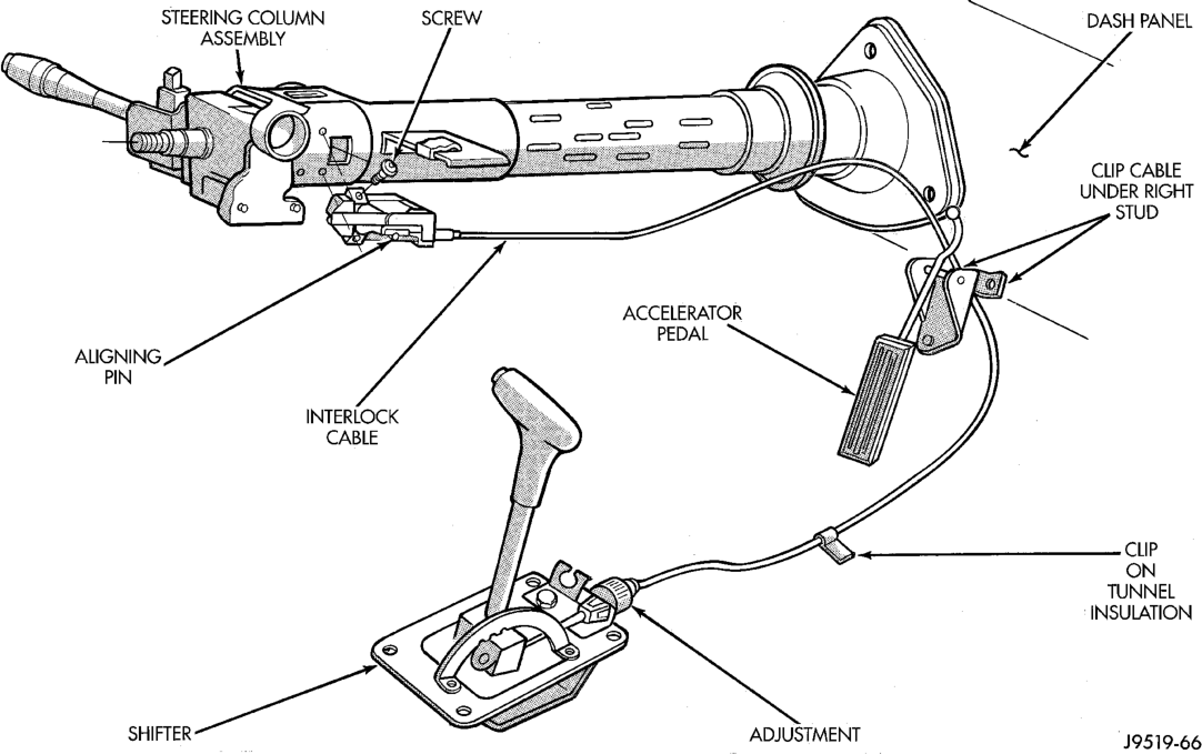
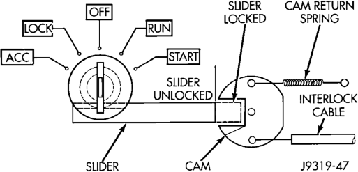
The Brake Transmission Shifter/Ignition Interlock (BTSI), is a cable and solenoid operated system. It interconnects the automatic transmission floor mounted shifter to the steering column ignition switch (Fig. 6). The system locks the shifter into the PARK position. The Interlock system is engaged whenever the ignition switch is in the LOCK or ACCESSORY position. An additional electrically activated feature will prevent shifting out of the PARK position unless the brake pedal is depressed at least one-half an inch. A magnetic holding device in line with the park lock cable is enegized when the ignition is in the RUN position.When the key is in the RUN position and the brake pedal is depressed, the shifter is unlocked and will move into any position. The interlock system also prevents the ignition switch from being turned to the LOCK or ACCES- SORY position (Fig. 7), unless the shifter is fully locked into the PARK position.
DIAGNOSIS AND TESTING
AUTOMATIC TRANSMISSION DIAGNOSIS
Automatic transmission problems can be a result of poor engine performance, incorrect fluid level, incorrect linkage or cable adjustment, band or hydraulic control pressure adjustments, hydraulic system malfunctions or electrical/mechanical component malfunctions. Begin diagnosis by checking the easily accessible items such as: fluid level and condition, linkage adjustments and electrical connections. A road test will determine if further diagnosis is necessary.
PRELIMINARY DIAGNOSIS
Two basic procedures are required. One procedure for vehicles that are drivable and an alternate procedure for disabled vehicles (will not back up or move forward).
VEHICLE IS DRIVEABLE
(1) Check for transmission fault codes using DRB scan tool.
(2) Check fluid level and condition. (3) Adjust throttle and gearshift linkage if complaint was based on delayed, erratic, or harsh shifts.
(4) Road test and note how transmission upshifts, downshifts, and engages.
(5) Perform stall test if complaint is based on sluggish acceleration. Or, if abnormal throttle opening is needed to maintain normal speeds with a properly tuned engine.
(6) Perform hydraulic pressure test if shift problems were noted during road test.
(7) Perform air-pressure test to check clutch-band operation.
VEHICLE !S DISABLED
(1) Check fluid level and condition. (2) Check for broken or disconnected gearshift or throttle linkage.
(3) Check for cracked, leaking cooler lines, or loose or missing pressure-port plugs.
(4) Raise and support vehicle on safety stands, start engine, shift transmission into gear, and note following:
(a) If propeller shaft turns but wheels do not, problem is with differential or axle shafts.
(b) If propeller shaft does not turn and transmission is noisy, stop engine. Remove oil pan, and check for debris. If pan is clear, remove transmission and check for damaged drive plate, converter, oil pump, or input shaft.
(c) If propeller shaft does not turn and transmission is not noisy, perform hydraulic-pressure test to determine if problem is hydraulic or mechanical.
PARK/NEUTRAL POSITION SWITCH
The center terminal of the park/neutral position switch is the starter-circuit terminal. It provides the ground for the starter solenoid circuit through the selector lever in PARK and NEUTRAL positions only. The outer terminals on the switch are for the backup lamp circuit.
SWITCH TEST
To test the switch, remove the wiring connector. Test for continuity between the center terminal and the transmission case. Continuity should exist only when the transmission is in PARK or NEUTRAL.
Shift the transmission into REVERSE and test continuity at the switch outer terminals. Continuity should exist only when the transmission is in REVERSE. Continuity should not exist between the outer terminals and the case.
Check gearshift linkage adjustment before replacing a switch that tests faulty.
OVERDRIVE ELECTRICAL CONTROLS
The overdrive off switch, valve body solenoid, case connectors and related wiring can all be tested with a 12 volt test lamp or a volt/ohmmeter. Check continuity of each component when diagnosis indicates this is necessary. Refer to Group 8W, Wiring Diagrams, for component locations and circuit information.
Switch and solenoid continuity should be checked whenever the transmission fails to shift into fourth gear range.
BRAKE TRANSMISSION SHIFT INTERLOCK
(1) Verify that the key can only be removed in the PARK position
(2) When the shift lever is in PARK And the shift handle pushbutton is in the “OUT” position, the ignition key cylinder should rotate freely from OFF to LOCK. When the shifter is in any other gear or neutral position, the ignition key cylinder should not rotate to the LOCK position.
(3) Shifting out of PARK should be possible when the ignition key cylinder is in the OFF position.
(4) Shifting out of PARK should not be possible while applying 25 lb. maximum handle pushbutton force and ignition key cylinder is in the RUN or START positions unless the foot brake pedal is depressed approximately 1/2 inch (12mm).
(5) Shifting out of PARK should not be possible when the ignition key cylinder is in the ACCESSORY or LOCK positions.
(6) Shifting between any gears, NEUTRAL or into PARK may be done without depressing foot brake pedal with ignition switch in RUN or START positions and vehicle stationary or in motion.
GEARSHIFT CABLE
(1) The floor shifter lever and gate positions should be in alignment with all transmission PARK, NEUTRAL, and gear detent positions.
(2) Engine starts must be possible with floor shift lever in PARK or NEUTRAL gate positions only. Engine starts must not be possible in any other gear position.
(3) With floor shift lever handle push-button not depressed and lever in:
(a) PARK position—Apply forward force on center of handle and remove pressure. Engine starts must be possible.
(b) PARK position—Apply rearward force on center of handle and remove pressure. Engine starts must be possible.
(c) NEUTRAL position—Normal position. Engine starts must be possible.
(d) NEUTRAL position—Engine running and brakes applied, apply forward force on center of shift handle. Transmission shall not be able to shift from neutral to reverse.
THROTTLE VALVE CABLE
Transmission throttle valve cable adjustment is extremely important to proper operation. This adjustment positions the throttle valve, which controls shift speed, quality, and part-throttle downshift sensitivity.
If cable setting is too loose, early shifts and slippage between shifts may occur. If the setting is too tight, shifts may be delayed and part throttle downshifts may be very sensitive. Refer to the Adjustments section for the proper adjustment procedure.
ROAD TESTING
Before road testing, be sure the fluid level and control cable adjustments have been checked and adjusted if necessary. Verify that diagnostic trouble codes have been resolved.
Observe engine performance during the road test. A poorly tuned engine will not allow accurate analysis of transmission operation.
Operate the transmission in all gear ranges. Check for shift variations and engine flare which indicates slippage. Note if shifts are harsh, spongy, delayed, early, or if part throttle downshifts are sensitive.
Slippage indicated by engine flare, usually means clutch, band or overrunning clutch problems. If the condition is advanced, an overhaul will be necessary to restore normal operation.
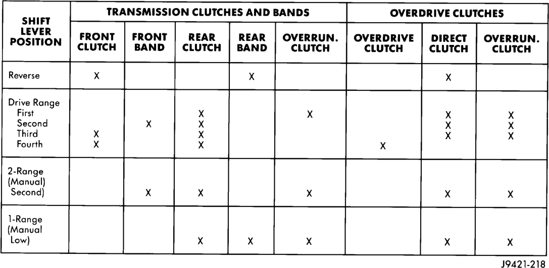
A slipping clutch or band can often be determined by comparing which internal units are applied in the various gear ranges. The Clutch and Band Application chart provides a basis for analyzing road test results.
ANALYZING ROAD TEST
Refer to the Clutch and Band Application chart and note which elements are in use in the various gear ranges.
Note that the rear clutch is applied in all forward ranges (D, 2, 1). The transmission overrunning clutch is applied in first gear (D, 2 and 1 ranges) only. The rear band is applied in 1 and R range only.
Note that the overdrive clutch is applied only in fourth gear and the overdrive direct clutch and over-
Clutch And Band Application Chart
running clutch are applied in all ranges except fourth gear.
For example: If slippage occurs in first gear in D and 2 range but not in 1 range, the transmission overrunning clutch is faulty. Similarly, if slippage occurs in any two forward gears, the rear clutch is slipping.
Applying the same method of analysis, note that the front and rear clutches are applied simultaneously only in D range third and fourth gear. If the transmission slips in third gear, either the front clutch or the rear clutch is slipping.
If the transmission slips in fourth gear but not in third gear, the overdrive clutch is slipping. By selecting another gear which does not use these clutches, the slipping unit can be determined. For example, if the transmission also slips in Reverse, the front clutch is slipping. If the transmission does not slip in Reverse, the rear clutch is slipping.
If slippage occurs during the 3-4 shift or only in fourth gear, the overdrive clutch is slipping. Similarly, if the direct clutch were to fail, the transmission would lose both reverse gear and overrun braking in 2 position (manual second gear).
If the transmission will not shift to fourth gear, the control switch, overdrive solenoid or related wiring may also be the problem cause.
This process of elimination can be used to identify a slipping unit and check operation. Proper use of the Clutch and Band Application Chart is the key.
Although road test analysis will help determine the slipping unit, the actual cause of a malfunction usu-
ally cannot be determined until hydraulic and air pressure tests are performed. Practically any condition can be caused by leaking hydraulic circuits or sticking valves.
Unless a malfunction is obvious, such as no drive in D range first gear, do not disassemble the transmission. Perform the hydraulic and air pressure tests to help determine the probable cause.
HYDRAULIC PRESSURE TEST
Hydraulic test pressures range from a low of one psi (6.895 kPa) governor pressure, to 300 psi (2068 kPa) at the rear servo pressure port in reverse.
An accurate tachometer and pressure test gauges are required. Test Gauge C-3292 has a 100 psi range and is used at the accumulator, governor, and front servo ports. Test Gauge C-3293-SP has a 300 psi range and is used at the rear servo and overdrive ports where pressures exceed 100 psi.
Pressure Test Port Locations
Test ports are located at both sides of the transmission case (Fig. 8).
Line pressure is checked at the accumulator port on the right side of the case. The front servo pressure port is at the right side of the case just behind the filler tube opening.
The rear servo and governor pressure ports are at the right rear of the transmission case. The overdrive clutch pressure port is at the left rear of the case.
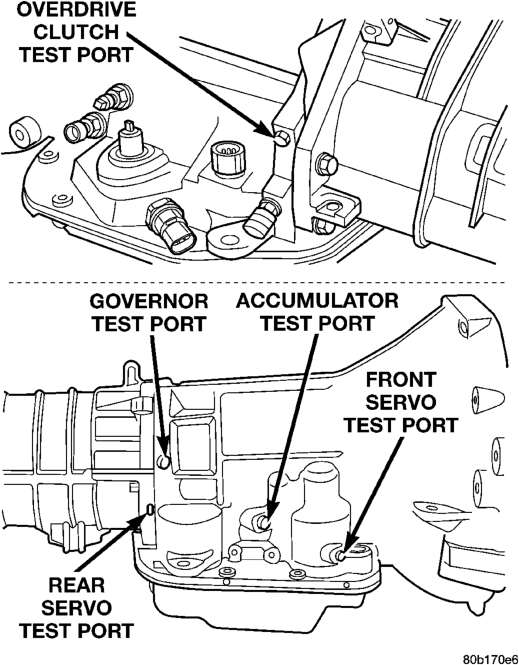
Test One - Transmission In Manual Low
NOTE: This test checks pump output, pressure regulation, and condition of the rear clutch and servo circuit. Both test gauges are required for this test.
(1) Connect tachometer to engine. Position tachometer so it can be observed from driver seat if helper will be operating engine. Raise vehicle on hoist that will allow rear wheels to rotate freely.
(2) Connect 100 psi Gauge C-3292 to accumulator port. Then connect 300 psi Gauge C-3293-SP to rear servo port.
(3) Disconnect throttle and gearshift cables from levers on transmission valve body manual shaft.
(4) Have helper start and run engine at 1000 rpm. (5) Move transmission shift lever fully forward into 1 range. (6) Gradually move transmission throttle lever from full forward to full rearward position and note pressures on both gauges:
• Line pressure at accumulator port should be 54-60 psi (372-414 kPa) with throttle lever forward and gradually increase to 90-96 psi (621-662 kPa) as throttle lever is moved rearward.
• Rear servo pressure should be same as line pressure within 3 psi (20.68 kPa).
Test Two—Transmission In 2 Range
NOTE: This test checks pump output, line pressure and pressure regulation. Use 100 psi Test Gauge C-3292 for this test.
(1) Leave vehicle in place on hoist and leave Test Gauge C-3292 connected to accumulator port.
(2) Have helper start and run engine at 1000 rpm. (3) Move transmission shift lever one detent rearward from full forward position. This is 2 range.
(4) Move transmission throttle lever from full forward to full rearward position and read pressure on gauge.
(5) Line pressure should be 54-60 psi (372-414 kPa) with throttle lever forward and gradually increase to 90-96 psi (621-662 kPa) as lever is moved rearward.
Test Three—Transmission In D Range Third Gear
NOTE: This test checks pressure regulation and condition of the clutch circuits. Both test gauges are required for this test.
(1) Turn OD switch off. (2) Leave vehicle on hoist and leave Gauge C-3292 in place at accumulator port. (3) Move Gauge C-3293-SP over to front servo port for this test.
(4) Have helper start and run engine at 1600 rpm for this test.
(5) Move transmission shift lever two detents rearward from full forward position. This is D range.
(6) Read pressures on both gauges as transmission throttle lever is gradually moved from full forward to full rearward position:
• Line pressure at accumulator in D range third gear, should be 54-60 psi (372-414 kPa) with throttle lever forward and increase as lever is moved rearward.
• Front servo pressure in D range third gear, should be within 3 psi (21 kPa) of line pressure up to kickdown point.
Test Four—Transmission In Reverse
NOTE: This test checks pump output, pressure regulation and the front clutch and rear servo circuits. Use 300 psi Test Gauge C-3293-SP for this test.
(1) Leave vehicle on hoist and leave gauge C3292 in place at accumulator port. (2) Move 300 psi Gauge C-3293-SP back to rear servo port.
(3) Have helper start and run engine at 1600 rpm for test.
(4) Move transmission shift lever four detents rearward from full forward position. This is Reverse range.
(5) Move transmission throttle lever fully forward then fully rearward and note reading at Gauge C-3293-SP.
(6) Pressure should be 145 - 175 psi (1000-1207 kPa) with throttle lever forward and increase to 230 - 280 psi (1586-1931 kPa) as lever is gradually moved rearward.
Test Five—Governor Pressure
NOTE: This test checks governor operation by measuring governor pressure response to changes in vehicle speed. It is usually not necessary to check governor operation unless shift speeds are incorrect or if the transmission will not downshift. The test should be performed on the road or on a hoist that will allow the rear wheels to rotate freely.
(1) Move 100 psi Test Gauge C-3292 to governor pressure port.
(2) Move transmission shift lever two detents rearward from full forward position. This is D range.
(3) Have helper start and run engine at curb idle speed. Then firmly apply service brakes so wheels will not rotate.
(4) Note governor pressure: • Governor pressure should be no more than 20.6 kPa (3 psi) at curb idle speed and wheels not rotating. • If pressure exceeds 20.6 kPa (3 psi), a fault exists in governor pressure control system.
(5) Release brakes, slowly increase engine speed, and observe speedometer and pressure test gauge (do not exceed 30 mph on speedometer). Governor pressure should increase in proportion to vehicle speed. Or approximately 6.89 kPa (1 psi) for every 1 mph.
(6) Governor pressure rise should be smooth and drop back to no more than 20.6 kPa (3 psi), after engine returns to curb idle and brakes are applied to prevent wheels from rotating.
(7) Compare results of pressure test with analysis chart.
Test Six—Transmission In Overdrive Fourth Gear
NOTE: This test checks line pressure at the overdrive clutch in fourth gear range. Use 300 psi Test Gauge C-3292 for this test. The test should be performed on the road or on a chassis dyno.
(1) Remove tachometer; it is not needed for this test.
(2) Move 300 psi Gauge to overdrive clutch pressure test port. Then remove other gauge and reinstall test port plug.
(3) Lower vehicle. (4) Turn OD switch on. (5) Secure test gauge so it can be viewed from drivers seat.
(6) Start engine and shift into D range. (7) Increase vehicle speed gradually until 3-4 shift occurs and note gauge pressure.
(8) Pressure should be 469-496 kPa (68-72 psi) with closed throttle and increase to 620-827 kPa (90- 120 psi) at 1/2 to 3/4 throttle. Note that pressure can increase to around 896 kPa (130 psi) at full throttle. (9) Return to shop or move vehicle off chassis dyno.
PRESSURE TEST ANALYSIS CHART
TEST CONDITION INDICATION
Line pressure OK during any one test
Pump and regulator valve OK
Line pressure OK in R but low in D, 2, 1
Leakage in rear clutch area (seal rings, clutch seals)
Pressure low in D Fourth Gear Range
Overdrive clutch piston seal, or check ball problem
Pressure OK in 1, 2 but low in D3 and R
Leakage in front clutch area
Pressure OK in 2 but low in R and 1 Leakage in rear servo
Front servo pressure low in 2 Leakage in servo; broken servo ring or cracked servo piston
Pressure low in all positions
Clogged filter, stuck regulator valve, worn or faulty pump, low oil level
Governor pressure too high at idle speed
Governor pressure solenoid valve system fault. Refer to diagnostic book.
Governor pressure low at all mph figures
Faulty governor pressure solenoid, transmission control module, or governor pressure sensor
Lubrication pressure low at all throttle positions
Clogged fluid cooler or lines, seal rings leaking, worn pump bushings, pump, clutch retainer, or clogged filter.
Line pressure high Output shaft plugged, sticky regulator valve
Line pressure low Sticky regulator valve, clogged filter, worn pump
CONVERTER STALL TEST
Stall testing involves determining maximum engine speed obtainable at full throttle with the rear wheels locked and the transmission in D range. This test checks the holding ability of the converter overrunning and transmission clutches.
WARNING: NEVER ALLOW ANYONE TO STAND DIRECTLY IN LINE WITH THE VEHICLE FRONT OR REAR DURING A STALL TEST. ALWAYS BLOCK THE WHEELS AND FULLY APPLY THE SERVICE AND PARKING BRAKES DURING THE TEST.
STALL TEST PROCEDURE
(1) Connect tachometer to engine. Position tachometer so it can be viewed from driver's seat.
(2) Drive vehicle to bring transmission fluid up to normal operating temperature. Vehicle can be driven on road or on chassis dynamometer, if available.
(3) Check transmission fluid level. Add fluid if necessary.
(4) Block front wheels. (5) Fully apply service and parking brakes. (6) Open throttle completely and record maximum engine speed registered on tachometer. It takes 4-10 seconds to reach max rpm. Once max rpm has been achieved, do not hold wide open throttle for more than 4-5 seconds.
CAUTION: Stalling the converter causes a rapid increase in fluid temperature. To avoid fluid overheating, hold the engine at maximum rpm for no more than 5 seconds. If engine exceeds 2500 rpm during the test, release the accelerator pedal immediately; transmission clutch slippage is occurring.
(7) If a second stall test is required, cool down fluid before proceeding. Shift into NEUTRAL and run engine at 1000 rpm for 20-30 seconds to cool fluid.
STALL TEST ANALYSIS
Stall Speed Too High
If the stall speed exceeds 2500 rpm, transmission clutch slippage is indicated.
Stall Speed Low
Low stall speed with a properly tuned engine indicate a torque converter overrunning clutch problem. The condition should be confirmed by road testing. A stall speed 250-350 rpm below normal indicates the converter overrunning clutch is slipping. The vehicle also exhibits poor acceleration but operates normally once highway cruise speeds are reached. Torque converter replacement will be necessary.
Stall Speed Normal But Acceleration Poor
If stall speeds are normal (1800-2300 rpm) but abnormal throttle opening is required for acceleration, or to maintain cruise speed, the converter overrunning clutch is seized. The torque converter will have to be replaced.
Converter Noise During Test
A whining noise caused by fluid flow is normal during a stall test. However, loud metallic noises indicate a damaged converter. To confirm that the noise is originating from the converter, operate the vehicle at light throttle in DRIVE and NEUTRAL on a hoist and listen for noise coming from the converter housing.
AIR TESTING TRANSMISSION CLUTCH AND BAND OPERATION
Air-pressure testing can be used to check transmission front/rear clutch and band operation. The test can be conducted with the transmission either in the vehicle or on the work bench, as a final check, after overhaul.
Air-pressure testing requires that the oil pan and valve body be removed from the transmission. The servo and clutch apply passages are shown (Fig. 9).
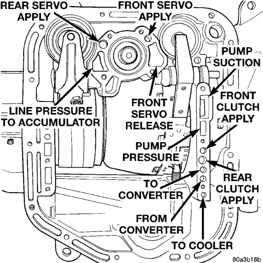
Front Clutch Air Test
Place one or two fingers on the clutch housing and apply air pressure through front clutch apply passage. Piston movement can be felt and a soft thump heard as the clutch applies.
Rear Clutch Air Test
Place one or two fingers on the clutch housing and apply air pressure through rear clutch apply passage. Piston movement can be felt and a soft thump heard as the clutch applies.
Front Servo Apply Air Test
Apply air pressure to the front servo apply passage. The servo rod should extend and cause the band to tighten around the drum. Spring pressure should release the servo when air pressure is removed.
Rear Servo Air Test
Apply air pressure to the rear servo apply passage. The servo rod should extend and cause the band to tighten around the drum. Spring pressure should release the servo when air pressure is removed.
CONVERTER HOUSING FLUID LEAK DIAGNOSIS
When diagnosing converter housing fluid leaks, two items must be established before repair.
(1) Verify that a leak condition actually exists. (2) Determined the true source of the leak. Some suspected converter housing fluid leaks may not be leaks at all. They may only be the result of residual fluid in the converter housing, or excess fluid spilled during factory fill or fill after repair. Converter housing leaks have several potential sources. Through careful observation, a leak source can be identified before removing the transmission for repair. Pump seal leaks tend to move along the drive hub and onto the rear of the converter. Pump O-ring or pump body leaks follow the same path as a seal leak (Fig. 10). Pump vent or pump attaching bolt leaks are generally deposited on the inside of the converter housing and not on the converter itself (Fig. 10). Pump seal or gasket leaks usually travel down the inside of the converter housing. Front band lever pin plug leaks are generally deposited on the housing and not on the converter.
TORQUE CONVERTER LEAK POINTS
Possible sources of converter leaks are: (1) Leaks at the weld joint around the outside diameter weld (Fig. 11).
(2) Leaks at the converter hub weld (Fig. 11).
CONVERTER HOUSING AREA LEAK
CORRECTION
(1) Remove converter. (2) Tighten front band adjusting screw until band is tight around front clutch retainer. This prevents front/rear clutches from coming out when oil pump is removed.
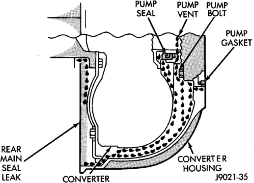
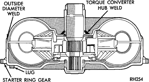
(3) Remove oil pump and remove pump seal. Inspect pump housing drainback and vent holes for obstructions. Clear holes with solvent and wire.
(4) Inspect pump bushing and converter hub. If bushing is scored, replace it. If converter hub is scored, either polish it with crocus cloth or replace converter.
(5) Install new pump seal, O-ring, and gasket. Replace oil pump if cracked, porous or damaged in any way. Be sure to loosen the front band before installing the oil pump, damage to the oil pump seal may occur if the band is still tightened to the front clutch retainer.
(6) Loosen kickdown lever pin access plug three turns. Apply Loctite 592, or Permatex No. 2 to plug threads and tighten plug to 17 N·m (150 in. lbs.) torque.
(7) Adjust front band. (8) Lubricate pump seal and converter hub with transmission fluid or petroleum jelly and install converter.
(9) Install transmission and converter housing dust shield.
(10) Lower vehicle.
DIAGNOSIS TABLES AND CHARTS—RE TRANSMISSION
The diagnosis charts provide additional reference when diagnosing a transmission fault. The charts provide general information on a variety of transmission, overdrive unit and converter clutch fault conditions.
DIAGNOSIS CHARTS
CONDITION POSSIBLE CAUSES CORRECTION
HARSH ENGAGEMENT (FROM NEUTRAL TO DRIVE OR REVERSE)
1. Fluid Level Low 1. Add Fluid
10. Clutch, band or planetary component damaged.
DELAYED ENGAGEMENT (FROM NEUTRAL TO DRIVE OR REVERSE)
2. Filter Clogged. 2. Change filter.
4. Torque Converter Drain Back (Oil drains from torque converter into transmission sump)
5. Rear Band Misadjusted. 5. Adjust band.
The hydraulic flow charts in the Schematics and Diagrams section of this group, outline fluid flow and hydraulic circuitry. Circuit operation is provided for neutral, third, fourth and reverse gear ranges. Normal working pressures are also supplied for each of the gear ranges .
2. Throttle Linkage Misadjusted 2. Adjust linkage - setting may be too long.
3. Mount and Driveline Bolts Loose 3. Check engine mount, transmission mount, propeller shaft, rear spring to body bolts, rear control arms, crossmember and axle bolt torque. Tighten loose bolts and replace missing bolts.
4. U-Joint Worn/Broken 4. Remove propeller shaft and replace U-Joint.
5. Axle Backlash Incorrect 5. Check per Service Manual. Correct as needed.
6. Hydraulic Pressure Incorrect 6. Check pressure. Remove, overhaul or adjust valve body as needed.
7. Band Misadjusted. 7. Adjust rear band.
8. Valve Body Check Balls Missing. 8. Inspect valve body for proper check ball installation.
9. Axle Pinion Flange Loose. 9. Replace nut and check pinion threads before installing new nut. Replace pinion gear if threads are damaged.
10. Remove, disassemble and repair transmission as necessary.
11. Converter Clutch Faulty. 11. Replace converter and flush cooler and line before installing new converter.
1. Fluid Level Low. 1. Correct level and check for leaks.
3. Gearshift Linkage Misadjusted. 3. Adjust linkage and repair linkage if worn or damaged.
4. If vehicle moves normally after 5 seconds after shifting into gear, no repair is necessary. If longer, inspect pump bushing for wear. Replace pump house.
6. Valve Body Filter Plugged. 6. Replace fluid and filter. If oil pan and old fluid were full of clutch disc material and/or metal particles, overhaul will be necessary.
7. Oil Pump Gears Worn/Damaged. 7. Remove transmission and replace oil pump.
CONDITION POSSIBLE CAUSES CORRECTION
8. Governor Circuit and Solenoid Valve Electrical Fault.
10. Reaction Shaft Seal Rings Worn/Broken.
11. Rear Clutch/Input Shaft, Rear Clutch Seal Rings Damaged.
12. Regulator Valve Stuck. 12. Clean.
NO DRIVE RANGE (REVERSE OK)
2. Gearshift Linkage/Cable Loose/Misadjusted.
5. Transmission Overrunning Clutch Broken.
6. Input Shaft Seal Rings Worn/Damaged.
NO DRIVE OR REVERSE (VEHICLE WILL NOT MOVE)
2. Gearshift Linkage/Cable Loose/Misadjusted.
3. U-Joint/Axle/Transfer Case Broken.
8. Test with DRB scan tool and repair as required.
9. Hydraulic Pressure Incorrect. 9. Perform pressure test, remove transmission and repair as needed.
10. Remove transmission, remove oil pump and replace seal rings.
11. Remove and disassemble transmission and repair as necessary.
13. Cooler Plugged. 13. Transfer case failure can plug cooler.
1. Fluid Level Low. 1. Add fluid and check for leaks if drive is restored.
2. Repair or replace linkage components.
3. Rear Clutch Burnt. 3. Remove and disassemble transmission and rear clutch and seals. Repair/replace worn or damaged parts as needed.
4. Valve Body Malfunction. 4. Remove and disassemble valve body. Replace assembly if any valves or bores are damaged.
5. Remove and disassemble transmission. Replace overrunning clutch.
6. Remove and disassemble transmission. Replace seal rings and any other worn or damaged parts.
7. Front Planetary Failed Broken. 7. Remove and repair.
1. Fluid Level Low. 1. Add fluid and check for leaks if drive is restored.
2. Inspect, adjust and reassemble linkage as needed. Replace worn/damaged parts.
3. Perform preliminary inspection procedure for vehicle that will not move. Refer to procedure in diagnosis section.
4. Filter Plugged. 4. Remove and disassemble transmission. Repair or replace failed components as needed. Replace filter. If filter and fluid contained clutch material or metal particles, an overhaul may be necessary. Perform lube flow test. Flush oil. Replace cooler as necessary.
5. Oil Pump Damaged. 5. Perform pressure test to confirm low pressure. Replace pump body assembly if necessary.
6. Valve Body Malfunctioned. 6. Check and inspect valve body. Replace valve body (as assembly) if any valve or bore is damaged. Clean and reassemble correctly if all parts are in good condition.
CONDITION POSSIBLE CAUSES CORRECTION
7. Transmission Internal Component Damaged.
8. Park Sprag not Releasing - Check Stall Speed, Worn/ Damaged/Stuck.
SHIFTS DELAYED OR ERRATIC (SHIFTS ALSO HARSH AT TIMES)
5. Gearshift Linkage/Cable Misadjusted.
8. Front Band Misadjusted. 8. Adjust band.
NO REVERSE (D RANGES OK)
1. Gearshift Linkage/Cable Misadjusted/Damaged.
7. Remove and disassemble transmission. Repair or replace failed components as needed.
8. Remove, disassemble, repair.
9. Torque Converter Damage. 9. Inspect and replace as required.
1. Fluid Level Low/High. 1. Correct fluid level and check for leaks if low.
2. Fluid Filter Clogged. 2. Replace filter. If filter and fluid contained clutch material or metal particles, an overhaul may be necessary. Perform lube flow test.
3. Throttle Linkage Misadjusted. 3. Adjust linkage as described in service section.
4. Throttle Linkage Binding. 4. Check cable for binding. Check for return to closed throttle at transmission.
5. Adjust linkage/cable as described in service section.
6. Clutch or Servo Failure. 6. Remove valve body and air test clutch, and band servo operation. Disassemble and repair transmission as needed.
7. Governor Circuit Electrical Fault. 7. Test using DRB scan tool and repair as required.
9. Pump Suction Passage Leak. 9. Check for excessive foam on dipstick after normal driving. Check for loose pump bolts, defective gasket. Replace pump assembly if needed.
1. Repair or replace linkage parts as needed.
2. Park Sprag Sticking. 2. Replace overdrive annulus gear.
3. Rear Band Misadjusted/Worn. 3. Adjust band; replace.
4. Valve Body Malfunction. 4. Remove and service valve body. Replace valve body if any valves or valve bores are worn or damaged.
5. Rear Servo Malfunction. 5. Remove and disassemble transmission. Replace worn/damaged servo parts as necessary.
6. Direct Clutch in Overdrive Worn 6. Disassemble overdrive. Replace worn or damaged parts.
7. Front Clutch Burnt. 7. Remove and disassemble transmission. Replace worn, damaged clutch parts as required.
CONDITION POSSIBLE CAUSES CORRECTION
HAS FIRST/REVERSE ONLY (NO 1-2 OR 2-3 UPSHIFT)
3. Front Servo/Kickdown Band Damaged/Burned.
MOVES IN 2ND OR 3RD GEAR, ABRUPTLY DOWNSHIFTS TO LOW
NO LOW GEAR (MOVES IN 2ND OR 3RD GEAR ONLY)
4. Front Servo Piston Cocked in Bore.
NO KICKDOWN OR NORMAL DOWNSHIFT
2. Accelerator Pedal Travel Restricted.
3. Valve Body Hydraulic Pressures Too High or Too Low Due to Valve Body Malfunction or Incorrect Hydraulic Control Pressure Adjustments.
1. Governor Circuit Electrical Fault. 1. Test using DRB scan tool and repair as required.
2. Valve Body Malfunction. 2. Repair stuck 1-2 shift valve or governor plug.
3. Repair/replace.
1. Valve Body Malfunction. 1. Remove, clean and inspect. Look for stuck 1-2 valve or governor plug.
2. Governor Valve Sticking. 2. Remove, clean and inspect. Replace faulty parts.
1. Governor Valve Sticking. 1. Remove governor, clean, inspect and repair as required.
2. Governor Circuit Electrical Fault. 2. Test with DRB scan tool and repair as required.
3. Valve Body Malfunction. 3. Remove, clean and inspect. Look for sticking 1-2 shift valve, 2-3 shift valve, governor plug or broken springs.
4. Inspect servo and repair as required.
5. Front Band Linkage Malfunction 5. Inspect linkage and look for bind in linkage.
1. Throttle Linkage Misadjusted. 1. Adjust linkage.
2. Verify floor mat is not under pedal, repair worn accelerator cable or bent brackets.
3. Perform hydraulic pressure tests to determine cause and repair as required. Correct valve body pressure adjustments as required.
4. Governor Circuit Electrical Fault. 4. Test with DRB scan tool and repair as required.
5. Valve Body Malfunction. 5. Perform hydraulic pressure tests to determine cause and repair as required. Correct valve body pressure adjustments as required.
6. TPS Malfunction. 6. Replace sensor, check with DRB scan tool.
7. PCM Malfunction. 7. Check with DRB scan tool and replace if required.
8. Valve Body Malfunction. 8. Repair sticking 1-2, 2-3 shift valves, governor plugs, 3-4 solenoid, 3-4 shift valve, 3-4 timing valve.
CONDITION POSSIBLE CAUSES CORRECTION
STUCK IN LOW GEAR (WILL NOT UPSHIFT)
1. Throttle Linkage Misadjusted/ Stuck.
3. Governor Component Electrical Fault.
4. Front Band Out of Adjustment. 4. Adjust Band.
CREEPS IN NEUTRAL 1. Gearshift Linkage Misadjusted. 1. Adjust linkage.
BUZZING NOISE 1. Fluid Level Low 1. Add fluid and check for leaks.
SLIPS IN REVERSE ONLY
3. Rear Band Misadjusted. 3. Adjust band.
1. Adjust linkage and repair linkage if worn or damaged. Check for binding cable or missing return spring.
2. Gearshift Linkage Misadjusted. 2. Adjust linkage and repair linkage if worn or damaged.
3. Check operating pressures and test with DRB scan tool, repair faulty component.
5. Clutch or Servo Malfunction. 5. Air pressure check operation of clutches and bands. Repair faulty component.
2. Rear Clutch Dragging/Warped. 2. Disassemble and repair.
3. Valve Body Malfunction. 3. Perform hydraulic pressure test to determine cause and repair as required.
2. Shift Cable Misassembled. 2. Route cable away from engine and bell housing.
3. Valve Body Misassembled. 3. Remove, disassemble, inspect valve body. Reassemble correctly if necessary. Replace assembly if valves or springs are damaged. Check for loose bolts or screws.
4. Pump Passages Leaking 4. Check pump for porous casting, scores on mating surfaces and excess rotor clearance. Repair as required. Loose pump bolts.
5. Cooling System Cooler Plugged. 5. Flow check cooler circuit. Repair as needed.
6. Overrunning Clutch Damaged. 6. Replace clutch.
1. Fluid Level Low. 1. Add fluid and check for leaks.
2. Gearshift Linkage Misadjusted. 2. Adjust linkage.
4. Rear Band Worn. 4. Replace as required.
5. Overdrive Direct Clutch Worn. 5. Disassemble overdrive. Repair as needed.
6. Hydraulic Pressure Too Low. 6. Perform hydraulic pressure tests to determine cause.
7. Rear Servo Leaking. 7. Air pressure check clutch-servo operation and repair as required.
8. Band Linkage Binding. 8. Inspect and repair as required.
CONDITION POSSIBLE CAUSES CORRECTION
SLIPS IN FORWARD DRIVE RANGES
6. Low Hydraulic Pressure Due to Worn Pump, Incorrect Control Pressure Adjustments, Valve Body Warpage or Malfunction, Sticking, Leaking Seal Rings, Clutch Seals Leaking, Servo Leaks, Clogged Filter or Cooler Lines
7. Rear Clutch Malfunction, Leaking Seals or Worn Plates.
8. Overrunning Clutch Worn, Not Holding (Slips in 1 Only).
SLIPS IN LOW GEAR 9D9 ONLY, BUT NO IN 1 POSITION
GROWLING, GRATING OR SCRAPING NOISES
1. Drive Plate Broken. 1. Replace.
2. Torque Converter Bolts Hitting Dust Shield.
3. Planetary Gear Set Broken/ Seized.
4. Overrunning Clutch Worn/ Broken.
5. Oil Pump Components Scored/Binding.
6. Output Shaft Bearing or Bushing Damaged.
8. Front and Rear Bands Misadjusted.
DRAGS OR LOCKS UP 1. Fluid Level Low. 1. Check and adjust level.
3. Front or Rear Band Misadjusted. 3. Adjust bands.
5. Servo Band or Linkage Malfunction.
1. Fluid Level Low. 1. Add fluid and check for leaks.
2. Fluid Foaming. 2. Check for high oil level, bad pump gasket or seals, dirt between pump halves and loose pump bolts. Replace pump if necessary.
3. Throttle Linkage Misadjusted. 3. Adjust linkage.
4. Gearshift Linkage Misadjusted. 4. Adjust linkage.
5. Rear Clutch Worn. 5. Inspect and replace as needed.
6. Perform hydraulic and air pressure tests to determine cause.
7. Air pressure check clutch-servo operation and repair as required.
8. Replace Clutch.
Overrunning Clutch Faulty. Replace overrunning clutch.
2. Dust shield bent. Replace or repair.
3. Check for debris in oil pan and repair as required.
4. Inspect and check for debris in oil pan. Repair as required.
5. Remove, inspect and repair as required.
6. Remove, inspect and repair as required.
7. Clutch Operation Faulty. 7. Perform air pressure check and repair as required.
8. Adjust bands.
2. Clutch Dragging/Failed 2. Air pressure check clutch operation and repair as required.
4. Case Leaks Internally. 4. Check for leakage between passages in case.
5. Air pressure check servo operation and repair as required.
6. Overrunning Clutch Worn. 6. Remove and inspect clutch. Repair as required.
CONDITION POSSIBLE CAUSES CORRECTION
NO 4-3 DOWNSHIFT 1. Circuit Wiring and/or Connectors Shorted.
NO 4-3 DOWNSHIFT WHEN CONTROL SWITCH IS TURNED OFF
2. Overdrive Solenoid Connector Shorted.
CLUNK NOISE FROM DRIVELINE ON CLOSED THROTTLE 4-3 DOWNSHIFT
1. Transmission Fluid Low. 1. Add Fluid.
2. Throttle Cable Misadjusted. 2. Adjust cable.
3. Overdrive Clutch Select Spacer Wrong Spacer.
3-4 UPSHIFT OCCURS IMMEDIATELY AFTER 2-3 SHIFT
1. Overdrive Solenoid Connector or Wiring Shorted.
WHINE/NOISE RELATED TO ENGINE SPEED
7. Planetary Gears Broken. 7. Remove, inspect and repair as required (look for debris in oil pan).
8. Converter Clutch Dragging. 8. Check for plugged cooler. Perform flow check. Inspect pump for excessive side clearance. Replace pump as required.
1. Test wiring and connectors with test lamp and volt/ohmmeter. Repair wiring as necessary. Replace connectors and/or harnesses as required.
2. PCM Malfunction. 2. Check PCM operation with DRB scan tool. Replace PCM only if faulty.
3. TPS Malfunction 3. Check TPS with DRB scan tool at PCM.
4. Lockup Solenoid Not Venting. 4. Remove valve body and replace solenoid assembly if plugged or shorted.
5. Overdrive Solenoid Not Venting. 5. Remove valve body and replace solenoid if plugged or shorted.
6. Valve Body Valve Sticking. 6. Repair stuck 3-4 shift valve or lockup timing valve.
1. Control Switch Open/Shorted. 1. Test and replace switch if faulty.
2. Test solenoids and replace if seized or shorted.
3. PCM Malfunction. 3. Test with DRB scan tool. Replace PCM if faulty.
4. Valve Body Stuck Valves. 4. Repair stuck 3-4, lockup or lockup timing valve.
3. Replace overdrive piston thrust plate spacer.
1. Test connector and wiring for loose connections, shorts or ground and repair as needed.
2. TPS Malfunction. 2. Test TPS and replace as necessary. Check with DRB scan tool.
3. PCM Malfunction. 3. Test PCM with DRB scan tool and replace controller if faulty.
4. Overdrive Solenoid Malfunction. 4. Replace solenoid.
5. Valve Body Malfunction. 5. Remove, disassemble, clean and inspect valve body components. Make sure all valves and plugs slide freely in bores. Polish valves with crocus cloth if needed.
1. Fluid Level Low. 1. Add fluid and check for leaks.
2. Shift Cable Incorrect Routing. 2. Check shift cable for correct routing. Should not touch engine or bell housing.
CONDITION POSSIBLE CAUSES CORRECTION
NO 3-4 UPSHIFT 1. Dash O/D Switch In OFF Position.
3. O/D Switch Wire Shorted/Open Cut.
4. Distance or Coolant Sensor Malfunction.
6. Neutral Switch to PCM Wire Shorted/Cut.
8. Overdrive Solenoid Shorted/ Open.
9. Solenoid Feed Orifice in Valve Body Blocked.
SLIPS IN OVERDRIVE FOURTH GEAR
3. Overdrive Piston Retainer Bleed Orifice Blown Out.
4. Overdrive Piston or Seal Malfunction.
5. 3-4 Shift Valve, Timing Valve or Accumulator Malfunction.
1. Turn control switch to ON position.
2. Overdrive Circuit Fuse Blown. 2. Replace fuse. Determine why fuse failed and repair as necessary (i.e., shorts or grounds in circuit).
3. Check wires/connections with 12V test lamp and voltmeter. Repair damaged or loose wire/connection as necessary.
4. Test both sensors with test lamp or volt/ohmmeter and replace faulty sensor.
5. TPS Malfunction. 5. Check with DRB scan tool and replace if necessary.
6. Test switch as described in service section and replace if necessary. Engine no start.
7. PCM Malfunction. 7. Check with DRB scan tool and replace if necessary.
8. Replace solenoid if shorted or open and repair loose or damaged wires (DRB scan tool).
9. Remove, disassemble, and clean valve body thoroughly. Check feed orifice.
10. Overdrive Clutch Failed. 10. Disassemble overdrive and repair as needed.
11. Hydraulic Pressure Low. 11. Pressure test transmission to determine cause.
12. Valve Body Valve Stuck. 12. Repair stuck 3-4 shift valve, 3-4 timing valve.
13. O/D Piston Incorrect Spacer. 13. Remove unit, check end play and install correct spacer.
14. Overdrive Piston Seal Failure. 14. Replace both seals.
15. O/D Check Valve/Orifice Failed. 15. Check for free movement and secure assembly (in piston retainer). Check ball bleed orifice.
1. Fluid Level Low. 1. Add fluid and check for leaks.
2. Overdrive Clutch Pack Worn. 2. Remove overdrive unit and rebuild clutch pack.
3. Disassemble transmission, remove retainer and replace orifice.
4. Remove overdrive unit. Replace seals if worn. Replace piston if damaged. If piston retainer is damaged, remove and disassemble the transmission.
5. Remove and overhaul valve body. Replace accumulator seals. Make sure all valves operate freely in bores and do not bind or stick. Make sure valve body screws are correctly tightened and separator plates are properly positioned.
CONDITION POSSIBLE CAUSES CORRECTION
6. Overdrive Unit Thrust Bearing Failure.
7. O/D Check Valve/Bleed Orifice Failure.
DELAYED 3-4 UPSHIFT (SLOW TO ENGAGE)
3. Overdrive Clutch Pack Worn/ Burnt.
5. Overdrive Clutch Bleed Orifice Plugged.
6. Overdrive Solenoid or Wiring Shorted/Open.
8. O/D Check Valve Missing or Stuck.
TORQUE CONVERTER LOCKS UP IN SECOND AND/OR THIRD GEAR
Lockup Solenoid, Relay or Wiring Shorted/Open.
HARSH 1-2, 2-3, 3-4 OR 3-2 SHIFTS
NO START IN PARK OR NEUTRAL
1. Gearshift Linkage/Cable Misadjusted.
5. Valve Body Manual Lever Assembly Bent/Worn/Broken.
NO REVERSE (OR SLIPS IN REVERSE)
1. Direct Clutch Pack (front clutch) Worn.
2. Rear Band Misadjusted. 2. Adjust band.
3. Front Clutch Malfunctioned/ Burned.
5. Direct Clutch Spring Collapsed/ Broken.
6. Disassemble overdrive unit and replace thrust bearing (NO. 1 thrust bearing is between overdrive piston and clutch hub; NO. 2 thrust bearing is between the planetary gear and the direct clutch spring plate; NO. 3 thrust bearing is between overrunning clutch hub and output shaft).
7. Check for function/secure orifice insert in O/D piston retainer.
1. Fluid Level Low. 1. Add fluid and check for leaks.
2. Throttle Valve Cable Misadjusted. 2. Adjust throttle valve cable.
3. Remove unit and rebuild clutch pack.
4. TPS Faulty. 4. Test with DRB scan tool and replace TPS.
5. Disassemble transmission and replace orifice.
6. Test solenoid and check wiring for loose/corroded connections or shorts/grounds. Replace solenoid if faulty and repair wiring if necessary.
7. Overdrive Excess Clearance 7. Remove unit. Measure end play and select proper spacer.
8. Check for presence of check valve. Repair or replace as required.
Test solenoid, relay and wiring for continuity, shorts or grounds. Replace solenoid and relay if faulty. Repair wiring and connectors as necessary.
Lockup Solenoid Malfunction. Remove valve body and replace solenoid assembly.
1. Adjust linkage/cable.
2. Neutral Switch Wire Open/Cut. 2. Check continuity with test lamp. Repair as required.
3. Neutral Switch Faulty. 3. Refer to service section for test and replacement procedure.
4. Neutral Switch Connect Faulty. 4. Connectors spread open. Repair.
5. Inspect lever assembly and replace if damaged.
1. Disassemble unit and rebuild clutch pack.
3. Air-pressure test clutch operation. Remove and rebuild if necessary.
4. Overdrive Thrust Bearing Failure. 4. Disassemble geartrain and replace bearings.
5. Remove and disassemble unit. Check clutch position and replace spring.
CONDITION POSSIBLE CAUSES CORRECTION
OIL LEAKS. 1. Speedometer Adapter Leaks. 1. Replace both adapter seals.
2. Fluid Lines and Fittings Loose/Leaks/Damaged.
3. Fill Tube (where tube enters case) Leaks/Damaged.
4. Pressure Port Plug Loose Loose/Damaged.
6. Valve Body Manual Lever Shaft Seal Leaks/Worn.
7. Rear Bearing Access Plate Leaks.
8. Gasket Damaged or Bolts are Loose.
9. Adapter/Extension Gasket Damaged Leaks/Damaged.
12. Pump Seal Leaks/Worn/ Damaged.
13. Torque Converter Weld Leak/Cracked Hub.
NOISY OPERATION IN FOURTH GEAR ONLY
1. Overdrive Clutch Discs, Plates or Snap Rings Damaged.
2. Overdrive Piston or Planetary Thrust Bearing Damaged.
3. Output Shaft Bearings Scored/ Damaged.
5. Overdrive Unit Overrunning Clutch Rollers Worn/Scored.
2. Tighten fittings. If leaks persist, replace fittings and lines if necessary.
3. Replace O-ring seal. Inspect tube for cracks in fill tube.
4. Tighten to correct torque. Replace plug or reseal if leak persists.
5. Pan Gasket Leaks. 5. Tighten pan screws (150 in. lbs.). If leaks persist, replace gasket.
6. Replace shaft seal.
7. Replace gasket. Tighten screws.
8. Replace bolts or gasket or tighten both.
9. Replace gasket.
10. Neutral Switch Leaks/Damaged. 10. Replace switch and gasket.
11. Converter Housing Area Leaks. 11. Check for leaks at seal caused by worn seal or burr on converter hub (cutting seal), worn bushing, missing oil return, oil in front pump housing or hole plugged. Check for leaks past O-ring seal on pump or past pump-to-case bolts; pump housing porous, oil coming out vent due to overfill or leak past front band shaft access plug.
12. Replace seal.
13. Replace converter.
14. Case Porosity Leaks. 14. Replace case.
1. Remove unit and rebuild clutch pack.
2. Remove and disassemble unit. Replace either thrust bearing if damaged.
3. Remove and disassemble unit. Replace either bearing if damaged.
4. Planetary Gears Worn/Chipped. 4. Remove and overhaul overdrive unit.
5. Remove and overhaul overdrive unit.
SERVICE PROCEDURES
FLUID LEVEL CHECK
Transmission fluid level should be checked monthly under normal operation. If the vehicle is used for trailer towing or similar heavy load hauling, check fluid level and condition weekly. Fluid level is checked with the engine running at curb idle speed, the transmission in NEUTRAL and the transmission fluid at normal operating temperature.
FLUID LEVEL CHECK PROCEDURE
(1) Transmission fluid must be at normal operating temperature for accurate fluid level check. Drive vehicle if necessary to bring fluid temperature up to normal hot operating temperature of 82°C (180°F).
(2) Position vehicle on level surface. (3) Start and run engine at curb idle speed. (4) Apply parking brakes. (5) Shift transmission momentarily into all gear ranges. Then shift transmission back to Neutral.
(6) Clean top of filler tube and dipstick to keep dirt from entering tube.
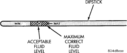
(7) Remove dipstick (Fig. 12) and check fluid level as follows:
(a) Correct acceptable level is in crosshatch area. (b) Correct maximum level is to MAX arrow mark.
(c) Incorrect level is at or below MIN line. (d) If fluid is low, add only enough Mopart ATF Plus 3 to restore correct level. Do not overfill.
CAUTION: Do not overfill the transmission. Overfilling may cause leakage out the pump vent which can be mistaken for a pump seal leak. Overfilling will also cause fluid aeration and foaming as the excess fluid is picked up and churned by the gear train. This will significantly reduce fluid life.
FLUID AND FILTER REPLACEMENT
Refer to the Maintenance Schedules in Group 0, Lubrication and Maintenance, for proper service intervals. The service fluid fill after a filter change is approximately 3.8 liters (4.0 quarts).
REMOVAL
(1) Hoist and support vehicle on safety stands. (2) Place a large diameter shallow drain pan beneath the transmission pan.
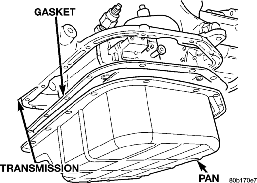
(3) Remove bolts holding front and sides of pan to transmission (Fig. 13).
(4) Loosen bolts holding rear of pan to transmission.
(5) Slowly separate front of pan away from transmission allowing the fluid to drain into drain pan.
(6) Hold up pan and remove remaining bolt holding pan to transmission. (7) While holding pan level, lower pan away from transmission.
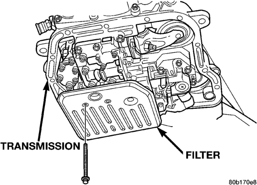
(8) Pour remaining fluid in pan into drain pan. (9) Remove screws holding filter to valve body (Fig. 14).
(10) Separate filter from valve body and pour fluid in filter into drain pan. (11) Dispose of used trans fluid and filter properly.
INSPECTION
Inspect bottom of pan and magnet for excessive amounts of metal. A light coating of clutch or band material on the bottom of the pan does not indicate a problem unless accompanied by slipping condition or shift lag. If fluid and pan are contaminated with excessive amounts or debris, refer to the diagnosis section of this group.
Check the adjustment of the front and rear bands, adjust if necessary.
CLEANING
(1) Using a suitable solvent, clean pan and magnet.
(2) Using a suitable gasket scraper, clean gasket material from gasket surface of transmission case and the gasket flange around the pan.
INSTALLATION
(1) Place replacement filter in position on valve body.
(2) Install screws to hold filter to valve body (Fig. 14). Tighten screws to 4 N·m (35 in. lbs.) torque.
(3) Place new gasket in position on pan and install pan on transmission.
(4) Place pan in position on transmission. (5) Install screws to hold pan to transmission (Fig. 13). Tighten bolts to 17 N·m (150 in. lbs.) torque.
(6) Lower vehicle and fill transmission with Mopart ATF Plus 3, type 7176 fluid.
TRANSMISSION FILL PROCEDURE
To avoid overfilling transmission after a fluid change or overhaul, perform the following procedure:
(1) Remove dipstick and insert clean funnel in transmission fill tube.
(2) Add following initial quantity of Mopart ATF Plus 3 to transmission:
(a) If only fluid and filter were changed, add 3 pints (1-1/2 quarts) of ATF Plus 3 to transmission.
(b) If transmission was completely overhauled, torque converter was replaced or drained, and cooler was flushed, add 12 pints (6 quarts) of ATF Plus 3 to transmission. (3) Apply parking brakes. (4) Start and run engine at normal curb idle speed.
(5) Apply service brakes, shift transmission through all gear ranges then back to NEUTRAL, set parking brake, and leave engine running at curb idle speed.
(6) Remove funnel, insert dipstick and check fluid level. If level is low, add fluid to bring level to MIN mark on dipstick. Check to see if the oil level is equal on both sides of the dipstick. If one side is noticably higher than the other, the dipstick has picked up some oil from the dipstick tube. Allow the oil to drain down the dipstick tube and re-check.
(7) Drive vehicle until transmission fluid is at normal operating temperature.
(8) With the engine running at curb idle speed, the gear selector in NEUTRAL, and the parking brake applied, check the transmission fluid level.
CAUTION: Do not overfill transmission, fluid foaming and shifting problems can result.
(9) Add fluid to bring level up to MAX arrow mark.
When fluid level is correct, shut engine off, release park brake, remove funnel, and install dipstick in fill tube.
CONVERTER DRAINBACK CHECK VALVE SERVICE
The converter drainback check valve is located in the cooler outlet (pressure) line near the radiator lower tank. The valve prevents fluid drainback when the vehicle is parked for lengthy periods. The valve check ball is spring loaded and has an opening pressure of approximately 2 psi.
The valve is serviced as an assembly; it is not repairable. Do not clean the valve if restricted, or contaminated by sludge, or debris. If the valve fails, or if a transmission malfunction occurs that generates sludge and/or clutch particles and metal shavings, the valve must be replaced. The valve must be removed whenever the cooler and lines are reverse flushed. The valve can be flow tested when necessary. The procedure is exactly the same as for flow testing a cooler.
If the valve is restricted, installed backwards, or in the wrong line, it will cause an overheating condition and possible transmission failure.
CAUTION: The drainback valve is a one-way flow device. It must be properly oriented in terms of flow direction for the cooler to function properly. The valve must be installed in the pressure line. Otherwise flow will be blocked and would cause an overheating condition and eventual transmission failure.
OIL PUMP VOLUME CHECK
After the new or repaired transmission has been installed, fill to the proper level with Mopart ATF PLUS 3 (Type 7176) automatic transmission fluid. The volume should be checked using the following procedure:
(1) Disconnect the From cooler line at the transmission and place a collecting container under the disconnected line.
CAUTION: With the fluid set at the proper level, fluid collection should not exceed (1) quart or internal damage to the transmission may occur.
(2) Run the engine at curb idle speed, with the shift selector in neutral.
(3) If fluid flow is intermittent or it takes more than 20 seconds to collect one quart of ATF PLUS 3, disconnect the To Cooler line at the transaxle.
(4) Refill the transaxle to proper level and recheck pump volume.
(5) If flow is found to be within acceptable limits, replace the cooler. Then fill transmission to the proper level, using Mopart ATF PLUS 3 (Type 7176) automatic transmission fluid.
(6) If fluid flow is still found to be inadequate, check the line pressure using the Transaxle Hydraulic Pressure Test procedure.
FLUSHING COOLERS AND TUBES
When a transmission failure has contaminated the fluid, the oil cooler(s) must be flushed. The cooler bypass valve in the transmission must be replaced also. The torque converter must also be replaced. This will insure that metal particles or sludged oil are not later transferred back into the reconditioned (or replaced) transmission.
The only recommended procedure for flushing coolers and lines is to use Tool 6906 Cooler Flusher.
WARNING: WEAR PROTECTIVE EYEWEAR THAT MEETS THE REQUIREMENTS OF OSHA AND ANSI Z87.1–1968. WEAR STANDARD INDUSTRIAL RUB- BER GLOVES.
KEEP LIGHTED CIGARETTES, SPARKS, FLAMES, AND OTHER IGNITION SOURCES AWAY FROM THE AREA TO PREVENT THE IGNITION OF COMBUSTI- BLE LIQUIDS AND GASES. KEEP A CLASS (B) FIRE EXTINGUISHER IN THE AREA WHERE THE FLUSHER WILL BE USED.
KEEP THE AREA WELL VENTILATED. DO NOT LET FLUSHING SOLVENT COME IN CON- TACT WITH YOUR EYES OR SKIN: IF EYE CONTAM- INATION OCCURS, FLUSH EYES WITH WATER FOR 15 TO 20 SECONDS. REMOVE CONTAMINATED CLOTHING AND WASH AFFECTED SKIN WITH SOAP AND WATER. SEEK MEDICAL ATTENTION.
COOLER FLUSH USING TOOL 6906
(1) Remove cover plate filler plug on Tool 6906. Fill reservoir 1/2 to 3/4 full of fresh flushing solution. Flushing solvents are petroleum based solutions generally used to clean automatic transmission components. DO NOT use solvents containing acids, water, gasoline, or any other corrosive liquids.
(2) Reinstall filler plug on Tool 6906.
(3) Verify pump power switch is turned OFF. Connect red alligator clip to positive (+) battery post. Connect black (-) alligator clip to a good ground.
(4) Disconnect the cooler lines at the transmission.
NOTE: When flushing transmission cooler and lines, ALWAYS reverse flush.
(5) Connect the BLUE pressure line to the OUT- LET (From) cooler line.
(6) Connect the CLEAR return line to the INLET (To) cooler line
(7) Turn pump ON for two to three minutes to flush cooler(s) and lines. Monitor pressure readings and clear return lines. Pressure readings should stabilize below 20 psi. for vehicles equipped with a single cooler and 30 psi. for vehicles equipped with dual coolers. If flow is intermittent or exceeds these pressures, replace cooler.
(8) Turn pump OFF. (9) Disconnect CLEAR suction line from reservoir at cover plate. Disconnect CLEAR return line at cover plate, and place it in a drain pan.
(10) Turn pump ON for 30 seconds to purge flushing solution from cooler and lines. Turn pump OFF. (11) Place CLEAR suction line into a one quart container of Mopart ATF Plus 3, type 7176 automatic transmission fluid.
(12) Turn pump ON until all transmission fluid is removed from the one quart container and lines. This purges any residual cleaning solvent from the transmission cooler and lines. Turn pump OFF.
(13) Disconnect alligator clips from battery. Reconnect flusher lines to cover plate, and remove flushing adapters from cooler lines.
ALUMINUM THREAD REPAIR
Damaged or worn threads in the aluminum transaxle case and valve body can be repaired by the use of Heli-Coils, or equivalent. This repair consists of drilling out the worn-out damaged threads. Then tap the hole with a special Heli-Coil tap, or equivalent, and installing a Heli-Coil insert, or equivalent, into the hole. This brings the hole back to its original thread size.
Heli-Coil, or equivalent, tools and inserts are readily available from most automotive parts suppliers.
REMOVAL AND INSTALLATION
TRANSMISSION
The overdrive unit can be removed and serviced separately. It is not necessary to remove the entire transmission assembly to perform overdrive unit repairs.
If only the overdrive unit requires service, refer to the overdrive unit removal and installation procedures.
CAUTION: The transmission and torque converter must be removed as an assembly to avoid component damage. The converter drive plate, pump bushing, or oil seal can be damaged if the converter is left attached to the driveplate during removal. Be sure to remove the transmission and converter as an assembly.
REMOVAL
(1) Disconnect battery negative cable. (2) Disconnect and lower or remove necessary exhaust components.
(3) Remove engine-to-transmission bending braces. (4) Disconnect fluid cooler lines at transmission. (5) Remove starter motor. (6) Disconnect and remove crankshaft position sensor. Retain sensor attaching bolts.
CAUTION: The crankshaft position sensor will be damaged if the transmission is removed, or installed, while the sensor is still bolted to the engine block, or transmission (4.0L only). To avoid damage, be sure to remove the sensor before removing the transmission.
(7) Remove torque converter access cover. (8) If transmission is being removed for overhaul, remove transmission oil pan, drain fluid and reinstall pan.
(9) Remove fill tube bracket bolts and pull tube out of transmission. Retain fill tube seal. On 4 x 4 models, it will also be necessary to remove bolt attaching transfer case vent tube to converter housing (Fig. 15).
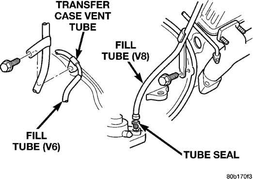
(10) Mark torque converter and drive plate for assembly alignment. Note that bolt holes in crankshaft flange, drive plate and torque converter all have one offset hole.
(11) Rotate crankshaft in clockwise direction until converter bolts are accessible. Then remove bolts one at a time. Rotate crankshaft with socket wrench on dampener bolt.
(12) Mark propeller shaft and axle yokes for assembly alignment. Then disconnect and remove propeller shaft. On 4 x 4 models, remove both propeller shafts.
(13) Disconnect wires from park/neutral position switch, transmission solenoid, and vehicle speed sensor.
(14) Disconnect gearshift cable from transmission manual valve lever.
(15) Disconnect throttle valve cable from transmission bracket and throttle valve lever.
(16) On 4 x 4 models, disconnect shift rod from transfer case shift lever or remove shift lever from transfer case.
(17) Disconnect transmission fluid cooler lines at transmission fittings and clips.
(18) Support rear of engine with safety stand or jack.
(19) Raise transmission slightly with service jack to relieve load on crossmember and supports.
(20) Remove bolts securing rear support and cushion to transmission and crossmember. Raise transmission slightly, slide exhaust hanger arm from bracket and remove rear support.
(21) Remove bolts attaching crossmember to frame and remove crossmember.
(22) On 4 x 4 models, remove transfer case. (23) Remove all converter housing bolts. (24) Carefully work transmission and torque converter assembly rearward off engine block dowels.
(25) Hold torque converter in place during transmission removal.
(26) Lower transmission and remove assembly from under the vehicle.
(27) To remove torque converter, carefully slide torque converter out of the transmission.
INSTALLATION
(1) Check torque converter hub and hub drive notches for sharp edges burrs, scratches, or nicks. Polish the hub and notches with 320/400 grit paper and crocus cloth if necessary. The hub must be smooth to avoid damaging pump seal at installation.
(2) Lubricate converter drive hub and oil pump seal lip with transmission fluid.
(3) Lubricate converter pilot hub with transmission fluid.
(4) Align converter and oil pump.
(5) Carefully insert converter in oil pump. Then rotate converter back and forth until fully seated in pump gears.
(6) Check converter seating with steel scale and straightedge (Fig. 16). Surface of converter lugs should be 1/2 in. to rear of straightedge when converter is fully seated.
(7) Temporarily secure converter with C-clamp.
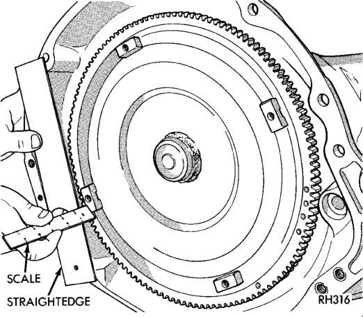
Seating
(8) Position transmission on jack and secure it with chains.
(9) Check condition of converter driveplate. Replace the plate if cracked, distorted or damaged. Also be sure transmission dowel pins are seated in engine block and protrude far enough to hold transmission in alignment.
(10) Raise transmission and align converter with drive plate and converter housing with engine block.
(11) Move transmission forward. Then raise, lower or tilt transmission to align converter housing with engine block dowels.
(12) Rotate converter so alignment marks scribed on converter are aligned with mark on driveplate.
(13) Carefully work transmission forward and over engine block dowels until converter hub is seated in crankshaft.
(14) Install bolts attaching converter housing to engine.
(15) Install rear support. Then lower transmission onto crossmember and install bolts attaching transmission mount to crossmember.
(16) Remove engine support fixture. (17) Install crankshaft position sensor. (18) Install vehicle speed sensor and speedometer adapter.
(19) Install new plastic retainer grommet on any shift linkage rod or lever that was disconnected. Grommets should not be reused. Use pry tool to remove rod from grommet and cut away old grommet. Use pliers to snap new grommet into lever and to snap rod into grommet at assembly.
(20) Connect gearshift and throttle valve cable to transmission.
(21) Connect wires to park/neutral position switch, transmission solenoid(s) and oxygen sensor. Be sure transmission harnesses are properly routed.
CAUTION: It is essential that correct length bolts be used to attach the converter to the driveplate. Bolts that are too long will damage the clutch surface inside the converter.
(22) Install torque converter-to-driveplate bolts. Tighten bolts to 31 N·m (270 in. lbs.).
(23) Install converter housing access cover. (24) Install starter motor and cooler line bracket. (25) Connect cooler lines to transmission. (26) Install transmission fill tube. Install new seal on tube before installation.
(27) Install exhaust components. (28) Install transfer case. (29) Align and connect propeller shaft(s). (30) Adjust gearshift linkage and throttle valve cable if necessary.
(31) Lower vehicle. (32) Fill transmission with Mopart ATF Plus 3, Type 7176 fluid.
TORQUE CONVERTER
REMOVAL
(1) Remove transmission and torque converter from vehicle.
(2) Place a suitable drain pan under the converter housing end of the transmission.
CAUTION: Verify that transmission is secure on the lifting device or work surface, the center of gravity of the transmission will shift when the torque converter is removed creating an unstable condition.
The torque converter is a heavy unit. Use caution when separating the torque converter from the transmission.
(3) Pull the torque converter forward until the center hub clears the oil pump seal.
(4) Separate the torque converter from the transmission.
INSTALLATION
Check converter hub and drive notches for sharp edges, burrs, scratches, or nicks. Polish the hub and notches with 320/400 grit paper or crocus cloth if necessary. The hub must be smooth to avoid damaging the pump seal at installation.
(1) Lubricate converter hub and oil pump seal lip with transmission fluid.
(2) Place torque converter in position on transmission.
CAUTION: Do not damage oil pump seal or bushing while inserting torque converter into the front of the transmission.
(3) Align torque converter to oil pump seal opening. (4) Insert torque converter hub into oil pump. (5) While pushing torque converter inward, rotate converter until converter is fully seated in the oil pump gears.
(6) Check converter seating with a scale and straightedge (Fig. 17). Surface of converter lugs should be 1/2 in. to rear of straightedge when converter is fully seated.
(7) If necessary, temporarily secure converter with C-clamp attached to the converter housing.
(8) Install the transmission in the vehicle. (9) Fill the transmission with the recommended fluid.
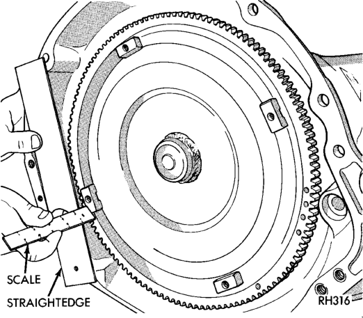
YOKE SEAL REPLACEMENT
REMOVAL
(1) Raise vehicle. (2) Mark propeller shaft and axle yoke for alignment reference.
(3) Disconnect and remove propeller shaft. (4) Remove old seal with Seal Remover C-3985-B (Fig. 18) from overdrive housing.
INSTALLATION
(1) Place seal in position on overdrive housing. (2) Drive seal into overdrive housing with Seal Installer C-3995-A (Fig. 19).
(3) Carefully guide propeller shaft slip yoke into housing and onto output shaft splines. Align marks made at removal and connect propeller shaft to rear axle pinion yoke.
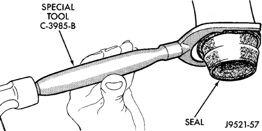
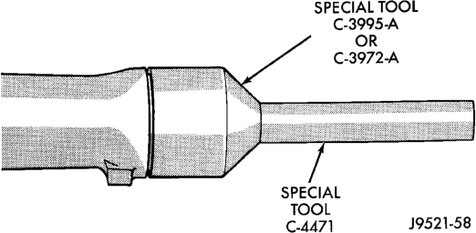
SPEEDOMETER ADAPTER
Rear axle gear ratio and tire size determine speedometer pinion requirements.
REMOVAL
(1) Raise vehicle. (2) Disconnect wires from vehicle speed sensor. (3) Remove adapter clamp and screw (Fig. 20). (4) Remove speed sensor and speedometer adapter as assembly.
(5) Remove speed sensor retaining screw and remove sensor from adapter.
(6) Remove speedometer pinion from adapter. (7) Inspect sensor and adapter O-rings (Fig. 20). Remove and discard O-rings if worn or damaged.
(8) Inspect terminal pins in speed sensor. Clean pins with Mopart electrical spray cleaner if dirty or oxidized. Replace sensor if faulty, or pins are loose, severely corroded, or damaged.
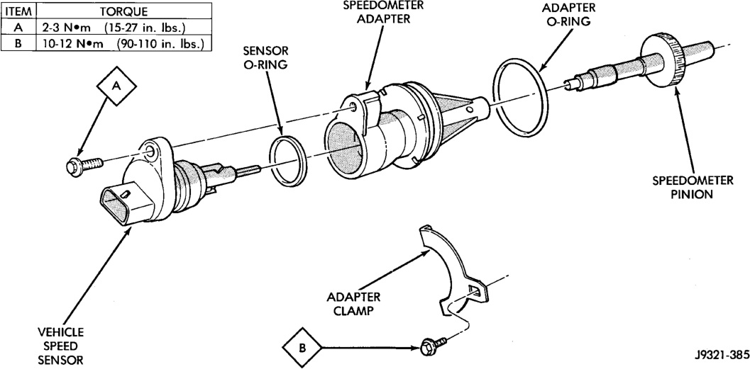
INSTALLATION
(1) Thoroughly clean adapter flange and adapter mounting surface in housing. Surfaces must be clean for proper adapter alignment and speedometer operation.
(2) Install new O-rings on speed sensor and speedometer adapter if necessary (Fig. 20).
(3) Lubricate sensor and adapter O-rings with transmission fluid.
(4) Install vehicle speed sensor in speedometer adapter. Tighten sensor attaching screw to 2-3 N·m (15-27 in. lbs.) torque.
(5) Install speedometer pinion in adapter. (6) Count number of teeth on speedometer pinion. Do this before installing assembly in housing. Then lubricate pinion teeth with transmission fluid.
(7) Note index numbers on adapter body (Fig. 21). These numbers will correspond to number of teeth on pinion.
(8) Install speedometer assembly in housing. (9) Rotate adapter until required range numbers are at 6 o'clock position. Be sure range index numbers correspond to number of teeth on pinion gear.
(10) Install speedometer adapter clamp and retaining screw. Tighten clamp screw to 10-12 N·m (90-110 in. lbs.) torque. (11) Connect wires to vehicle speed sensor. (12) Lower vehicle and top off transmission fluid level, if necessary.
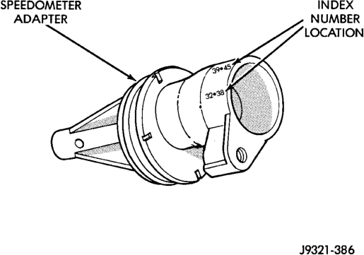
Adapter
PARK/NEUTRAL POSITION SWITCH
REMOVAL
(1) Raise vehicle and position drain pan under switch.
(2) Disconnect switch wires. (3) Remove switch from case.
INSTALLATION
(1) Move shift lever to Park and Neutral positions. Verify that switch operating lever fingers are centered in switch opening in case (Fig. 22).
(2) Install new seal on switch and install switch in case. Tighten switch to 34 N·m (25 ft. lbs.) torque.
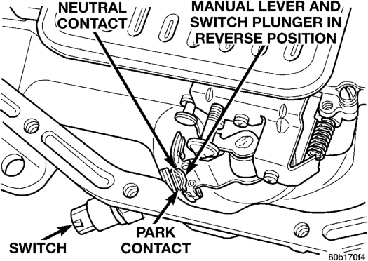
(3) Test continuity of new switch with 12V test lamp.
(4) Connect switch wires and lower vehicle. (5) Top off transmission fluid level.
GEARSHIFT CABLE
REMOVAL
(1) Shift transmission into Park. (2) Remove shift lever bezel and necessary console parts for access to shift lever assembly.
(3) Disconnect cable at shift lever and feed cable through dash panel opening to underside of vehicle.
(4) Raise vehicle. (5) Disengage cable eyelet at transmission shift lever and pull cable adjuster out of mounting bracket. Then remove old cable from vehicle.
INSTALLATION
(1) Route cable through hole in dash panel. Fully seat cable grommet into dash panel.
(2) Place the auto transmission manual shift control lever in “Park” detent (rearmost) position and rotate prop shaft to ensure transmission is in park.
(3) Connect shift cable to shifter mechanism by snapping cable retaining ears into shifter bracket and press cable end fitting onto lever ball stud.
(4) Place the floor shifter lever in park position. Ensure that the pawl is seated within the confines of the adjustment gauge clip.
(5) Snap the cable into the transmission bracket so the retaining ears are engaged and connect cable end fitting onto the manual control lever ball stud.
(6) Lock shift cable into position by pushing upward on the adjusting lock button.
(7) Remove and discard the shift cable adjustment gauge clip from the park gate of the shifter.
BRAKE TRANSMISSION SHIFT INTERLOCK
REMOVAL
(1) Lower the steering column. (2) Remove two screws retaining the interlock mechanism to the column (Fig. 23). Unsnap the mechanism from column.
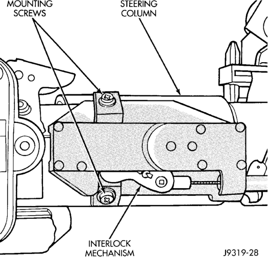
(3) Remove the center console and related trim. Refer to Group 23, Body, for proper procedures.
(4) Disconnect and remove the cable from the shift bracket.
(5) Remove the wire connector at the solenoid on the cable
(6) Remove the accelerator pedal (the cable routes under the pedal). Refer to Group 14, Fuel Systems, for proper procedures.
(7) Release the cable from the accelerator pedal clip.
(8) Remove the carpet as necessary to remove the cable.
INSTALLATION
NOTE: The gearshift cable must be secured into position and properly adjusted before the installation of the Brake Transmission Interlock Cable (BTSI).
(1) Snap the cable base assembly into the large square opening in the steering column.
(2) Secure the plastic base with two (2) self tapping screws (tighten upper screw first).
(3) Snap BTSI cable solenoid tie strap into hole in steering column tube.
(4) Route BTSI cable into two clips on carpet pad. (5) Snap electrical connector from brake light switch into BTSI cable solenoid housing.
(6) Snap BTSI cable adjuster ears into floor shifter bracket and attach cable end fitting onto floor shifter interlock lever stud. (7) Remove shipping pin from plastic base. Then place floor shifter in Park position.
(8) Place the ignition key cylinder in the ACCES- SORY position.
(9) Push the cable adjuster lock clamp downward to lock it.
(10) Remove and discard the BTSI cable nail head lockpin at steering column.
(11) Install the center console and related trim. Refer to Group 23, Body, for proper procedures.
(12) Test the BTSI cable operation.
GOVERNOR SOLENOID AND PRESSURE SENSOR
REMOVAL
(1) Hoist and support vehicle on safety stands. (2) Remove transmission fluid pan and filter. (3) Disengage wire connectors from pressure sensor and solenoid (Fig. 24).
(4) Remove screws holding pressure solenoid retainer to governor body.
(5) Separate solenoid retainer from governor (Fig. 25).
(6) Pull solenoid from governor body (Fig. 26). (7) Remove bolts holding governor body to valve body.
(8) Separate governor body from valve body (Fig. 27).
(9) Remove governor body gasket. (10) Remove retainer holding pressure sensor to governor body.
(11) Pull pressure sensor from governor body (Fig. 28).
INSTALLATION
Before installing the pressure sensor and solenoid in the governor body, replace O-ring seals, clean the gasket surfaces and replace gasket.
(1) Lubricate O-ring on pressure sensor with transmission fluid.
(2) Align pressure sensor to bore in governor body (Fig. 28).
(3) Push pressure sensor into governor body. (4) Install retainer to hold pressure sensor to governor body.
(5) Place gasket in position on back of governor body (Fig. 27).
(6) Place governor body in position on valve body.
(7) Install bolts to hold governor body to valve body.
(8) Lubricate O-ring, on pressure solenoid, with transmission fluid.
(9) Align pressure solenoid to bore in governor body (Fig. 26).
(10) Push solenoid into governor body. (11) Place solenoid retainer in position on governor (Fig. 25).
(12) Install screws to hold pressure solenoid retainer to governor body.
(13) Engage wire connectors into pressure sensor and solenoid (Fig. 24).
(14) Install transmission fluid pan and (new) filter. (15) Lower vehicle and road test to verify repair.
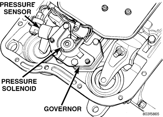
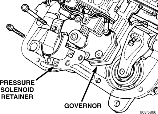
VALVE Body
The valve body can be removed for service without having to remove the transmission assembly.
The valve body can be disassembled for cleaning and inspection of the individual components. Refer to
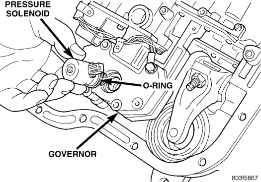
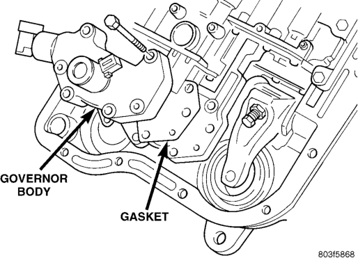
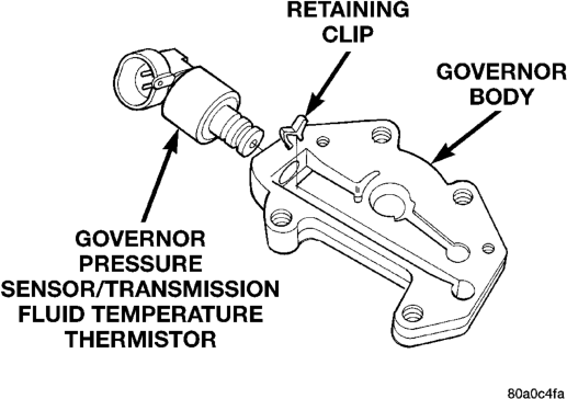
Disassembly and Assembly section for proper procedures.
The only replaceable valve body components are: • Manual lever.
• Manual lever washer, seal, E-clip, and shaft seal.
• Manual lever detent ball. • Throttle lever. • Fluid filter. • Pressure adjusting screw bracket. • Governor pressure solenoid. • Governor pressure sensor. • Converter clutch/overdrive solenoid assembly and harness (includes sump temperature thermistor).
• Governor housing gasket. • Solenoid case connector O-rings. The remaining valve body components are serviced only as part of a complete valve body assembly.
REMOVAL
(1) Shift transmission into NEUTRAL. (2) Raise vehicle. (3) Remove gearshift and throttle levers from shaft of valve body manual lever.
(4) Disconnect wires at solenoid case connector (Fig. 29).
(5) Position drain pan under transmission oil pan. (6) Remove transmission oil pan and gasket. (7) Remove fluid filter from valve body. (8) Remove bolts attaching valve body to transmission case.
(9) Lower valve body enough to remove accumulator piston and springs.
(10) Work manual lever shaft and electrical connector out of transmission case.
(11) Lower valve body, rotate valve body away from case, pull park rod out of sprag, and remove valve body (Fig. 30).
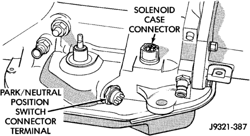
INSTALLATION
(1) Check condition of O-ring seals on valve body harness connector (Fig. 31). Replace seals on connector body if cut or worn.
(2) Check condition of manual lever shaft seal in transmission case. Replace seal if lip is cut or worn. Install new seal with 15/16 deep well socket (Fig. 32).
(3) Check condition of seals on accumulator piston (Fig. 33). Install new piston seals, if necessary.
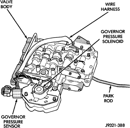
(4) Place valve body manual lever in low (1 position) so ball on park lock rod will be easier to install in sprag. (5) Lubricate shaft of manual lever with petroleum jelly. This will ease inserting shaft through seal in case.
(6) Lubricate seal rings on valve body harness connector with petroleum jelly.
(7) Position valve body in case and work end of park lock rod into and through pawl sprag. Turn propeller shaft to align sprag and park lock teeth if necessary. The rod will click as it enters pawl. Move rod to check engagement.
CAUTION: It is possible for the park rod to displace into a cavity just above the pawl sprag during installation. Make sure the rod is actually engaged in the pawl and has not displaced into this cavity.
(8) Install accumulator springs and piston into case. Then swing valve body over piston and outer spring to hold it in place.
(9) Align accumulator piston and outer spring, manual lever shaft and electrical connector in case.
(10) Then seat valve body in case and install one or two bolts to hold valve body in place.
(11) Tighten valve body bolts alternately and evenly to 11 N·m (100 in. lbs.) torque.
(12) Install new fluid filter on valve body. Tighten filter screws to 4 N·m (35 in. lbs.) torque.
(13) Install throttle and gearshift levers on valve body manual lever shaft.
(14) Check and adjust front and rear bands if necessary.
(15) Connect solenoid case connector wires. (16) Install oil pan and new gasket. Tighten pan bolts to 17 N·m (13 ft. lbs.) torque.
(17) Lower vehicle and fill transmission with Mopart ATF Plus 3, type 7176 fluid.
(18) Check and adjust gearshift and throttle valve cables, if necessary.
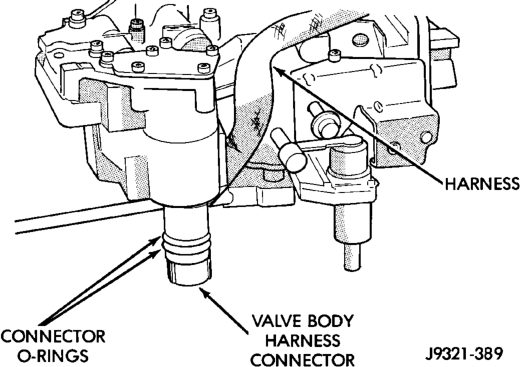
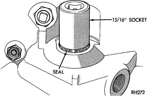
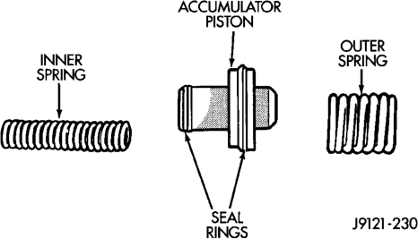
OVERDRIVE UNIT
REMOVAL
(1) Shift transmission into Park. (2) Raise vehicle. (3) Mark propeller shaft universal joint(s) and axle pinion yoke for alignment reference at installation.
(4) Disconnect and remove propeller shaft(s). (5) Remove transmission oil pan, remove gasket, drain oil and reinstall pan.
(6) If overdrive unit had malfunctioned, or if fluid is contaminated, remove entire transmission. If diagnosis indicated overdrive problems only, remove just the overdrive unit.
(7) Support transmission with transmission jack. (8) Remove vehicle speed sensor and speedometer adapter, if necessary.
(9) Remove bolts attaching overdrive unit to transmission (Fig. 34).
CAUTION: Support the overdrive unit with a jack before moving it rearward. This is necessary to prevent damaging the intermediate shaft. Do not allow the shaft to support the entire weight of the overdrive unit.
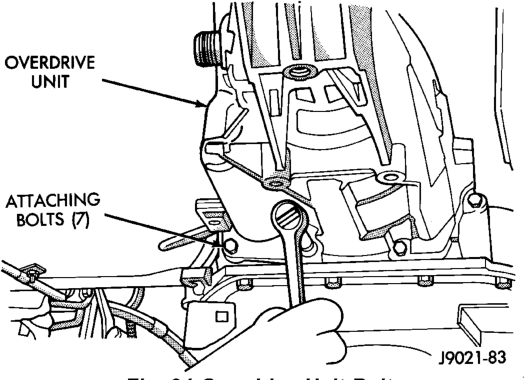
(10) Carefully work overdrive unit off intermediate shaft. Do not tilt unit during removal. Keep it as level as possible.
(11) If overdrive unit does not require service, immediately insert Alignment Tool 6227-2 in splines of planetary gear and overrunning clutch to prevent splines from rotating out of alignment. If misalignment occurs, overdrive unit will have to be disassembled in order to realign splines.
(12) Remove and retain overdrive piston thrust bearing. Bearing may remain on piston or in clutch hub during removal.
(13) Position drain pan on workbench. (14) Place overdrive unit over drain pan. Tilt unit to drain residual fluid from case.
(15) Examine fluid for clutch material or metal fragments. If fluid contains these items, overhaul will be necessary.
(16) If overdrive unit does not require any service, leave alignment tool in position. Tool will prevent accidental misalignment of planetary gear and overrunning clutch splines.
INSTALLATION
(1)
Be sure overdrive unit Alignment Tool 6227-2 is

have to be disassembled in order to realign splines.
(2) If overdrive piston retainer was not removed during service and original case gasket is no longer reusable, prepare new gasket by trimming it.
(3) Cut out old case gasket around piston retainer with razor knife (Fig. 35).
(4) Use old gasket as template and trim new gasket to fit.
(5) Position new gasket over piston retainer and on transmission case. Use petroleum jelly to hold gasket in place if necessary. Do not use any type of sealer to secure gasket. Use petroleum jelly only.
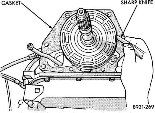
(6) Install selective spacer on intermediate shaft, if removed. Spacer goes in groove just rearward of shaft rear splines (Fig. 36).
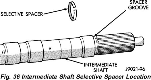
(7) Install thrust bearing in overdrive unit sliding hub. Use petroleum jelly to hold bearing in position.
CAUTION: Be sure the shoulder on the inside diameter of the bearing is facing forward.
(8) Verify that splines in overdrive planetary gear and overrunning clutch hub are aligned with Alignment Tool 6227-2. Overdrive unit cannot be installed if splines are not aligned. If splines have rotated out of alignment, unit will have to be disassembled to realign splines.
(9) Carefully slide Alignment Tool 6227-2 out of overdrive planetary gear and overrunning clutch splines.
(10) Raise overdrive unit and carefully slide it straight onto intermediate shaft. Insert park rod into park lock reaction plug at same time. Avoid tilting overdrive during installation as this could cause planetary gear and overrunning clutch splines to rotate out of alignment. If this occurs, it will be necessary to remove and disassemble overdrive unit to realign splines.
(11) Work overdrive unit forward on intermediate shaft until seated against transmission case.
(12) Install bolts attaching overdrive unit to transmission unit. Tighten bolts in diagonal pattern to 34 N·m (25 ft-lbs).
(13) Install speed sensor and speedometer adapter. Be sure to index adapter.
(14) Connect speed sensor and overdrive wires. (15) Align and install propeller shaft.
OVERDRIVE HOUSING BUSHING
REMOVAL
(1) Remove overdrive housing yoke seal. (2) Insert Remover 6957 into overdrive housing. Tighten tool to bushing and remove bushing (Fig. 37).
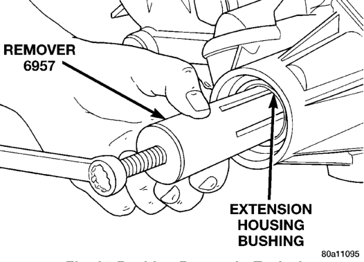
INSTALLATION
(1) Align bushing oil hole with oil slot in overdrive housing.
(2) Tap bushing into place with Installer 6951 and Handle C-4171.
(3) Install new oil seal in housing using Seal Installer C-3995–A (Fig. 38).
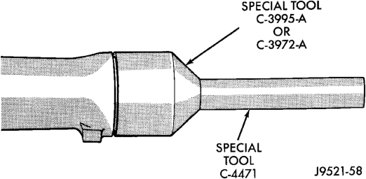
OUTPUT SHAFT REAR BEARING
REMOVAL
(1) Remove overdrive unit from the vehicle. (2) Remove overdrive geartrain from housing. (3) Remove snap ring holding output shaft rear bearing into overdrive housing (Fig. 39).
(4) Using a suitable driver inserted through the rear end of housing, drive bearing from housing.
INSTALLATION
(1) Place replacement bearing in position in housing. (2) Using a suitable driver, drive bearing into housing until the snap ring groove is visible.
(3) Install snap ring to hold bearing into housing (Fig. 39).
(4) Install overdrive geartrain into housing. (5) Install overdrive unit in vehicle.
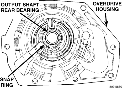
OUTPUT SHAFT FRONT BEARING
REMOVAL
(1) Remove overdrive unit from the vehicle. (2) Remove overdrive geartrain from housing. (3) Remove snap ring holding output shaft front bearing to overdrive geartrain. (Fig. 40).
(4) Pull bearing from output shaft.
INSTALLATION
(1) Place replacement bearing in position on geartrain with locating retainer groove toward the rear.
(2) Push bearing onto shaft until the snap ring groove is visible.
(3) Install snap ring to hold bearing onto output shaft (Fig. 40).
(4) Install overdrive geartrain into housing. (5) Install overdrive unit in vehicle.
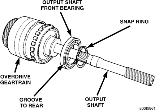
DISASSEMBLY AND ASSEMBLY
VALVE Body
Remove the valve body from the transmission, refer to Removal and Installation procedures section in this group.
DISASSEMBLY
CAUTION: Do not clamp any valve body component in a vise. This practice can damage the component resulting in unsatisfactory operation after assembly and installation. Do not use pliers to remove any of the valves, plugs or springs and do not force any of the components out or into place. The valves and valve body housings will be damaged if force is used. Tag or mark the valve body springs for reference as they are removed. Do not allow them to become intermixed.
(1) Remove fluid filter. (2) Disconnect wires from governor pressure sensor and solenoid.
(3) Remove screws attaching governor body and retainer plate to transfer plate.
(4) Remove retainer plate, governor body and gasket from transfer plate.
(5) Disconnect wires from governor pressure sensor, if not done previously.
(6) Remove governor pressure sensor from governor body. Sensor is retained in body with M-shaped spring clip. Remove clip with small pointed tool and slide sensor out of body.
(7) Remove governor pressure solenoid by pulling it straight out of bore in governor body. Remove and discard solenoid O-rings if worn, cut, or torn.
(8) Remove small shoulder bolt that secures solenoid harness case connector to 3-4 accumulator housing (Fig. 41). Retain shoulder bolt. Either tape it to harness or thread it back into accumulator housing after connector removal.
(9) Unhook overdrive/converter solenoid harness from 3-4 accumulator cover plate (Fig. 42).
(10) Turn valve body over and remove screws that attach overdrive/converter solenoid assembly to valve body (Fig. 43).
(11) Remove solenoid and harness assembly from valve body (Fig. 44).
(12) Remove boost valve cover (Fig. 45). (13) Remove boost valve retainer, valve spring and boost valve (Fig. 46).
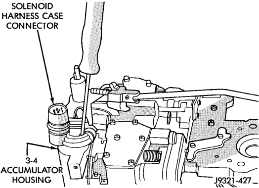
Bolt
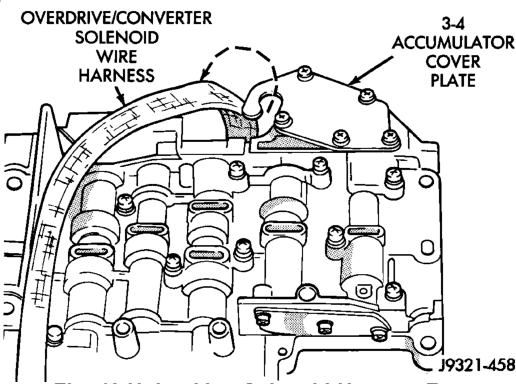
Accumulator Cover Plate
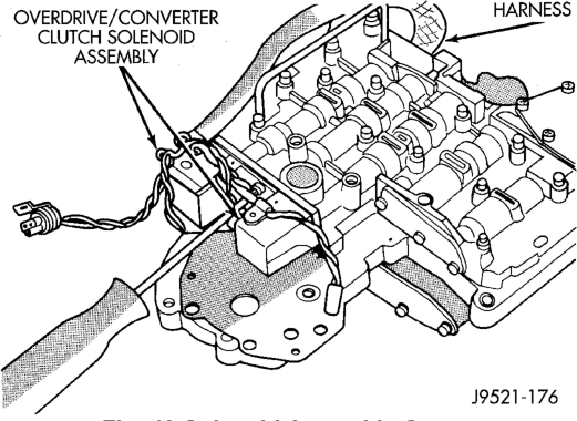
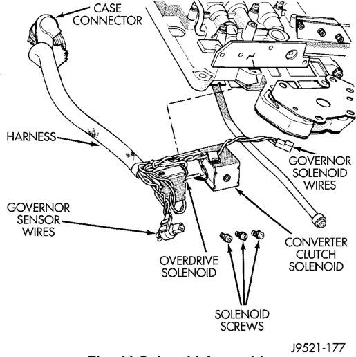
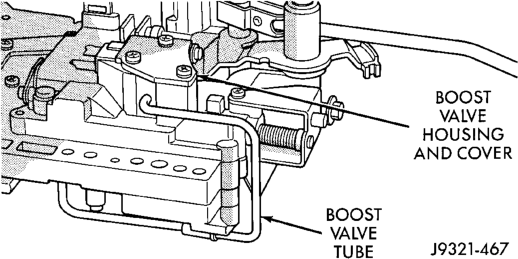
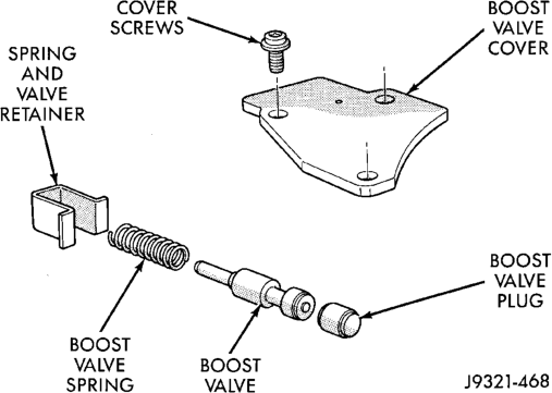
(14) Secure detent ball and spring with Retainer Tool 6583 (Fig. 47).
(15) Remove park rod E-clip and separate rod from manual lever (Fig. 48).
(16) Remove E-clip and washer that retains throttle lever shaft in manual lever (Fig. 49).
(17) Remove manual lever and throttle lever (Fig. 50). Rotate and lift manual lever off valve body and throttle lever shaft. Then slide throttle lever out of valve body.
(18) Position pencil magnet next to detent housing to catch detent ball and spring. Then carefully remove Retainer Tool 6583 and remove detent ball and spring (Fig. 51).
(19) Remove screws attaching pressure adjusting screw bracket to valve body and transfer plate (Fig. 52). Hold bracket firmly against spring tension while removing last screw.
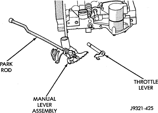
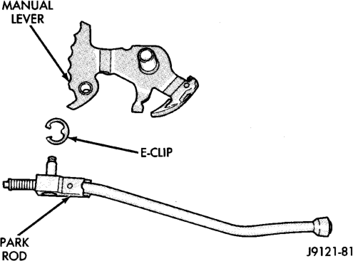
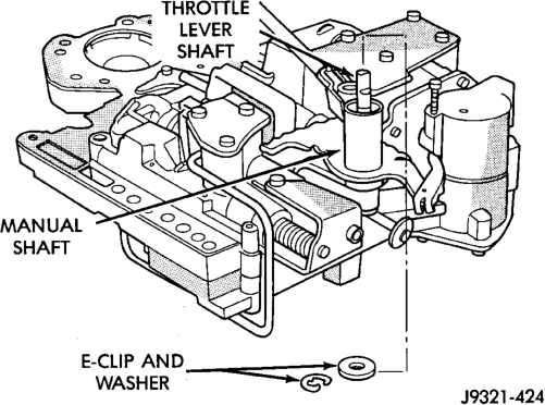
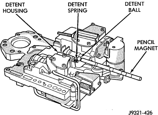
(20) Remove adjusting screw bracket, line pressure adjusting screw, pressure regulator valve spring and switch valve spring (Fig. 53). Do not remove throttle pressure adjusting screw from bracket and do not disturb setting of either adjusting screw during removal.
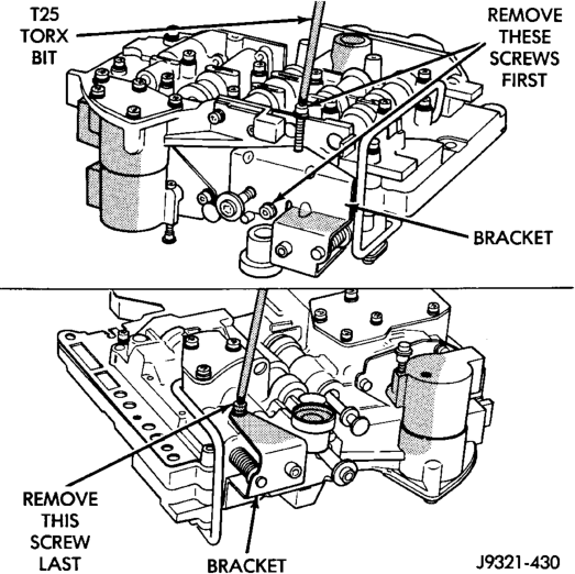
(21) Turn upper housing over and remove switch valve, regulator valve and spring, and manual valve (Fig. 54).
(22) Remove kickdown detent, kickdown valve, and throttle valve and spring (Fig. 54).
(23) Loosen left-side 3-4 accumulator housing attaching screw about 2-3 threads. Then remove center and right-side housing attaching screws (Fig. 55).
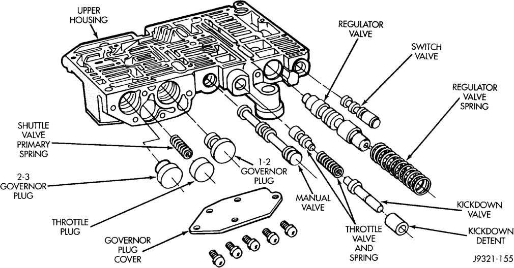
(24) Carefully rotate 3-4 accumulator housing upward and remove 3-4 shift valve spring and converter clutch valve plug and spring (Fig. 56).
(25) Remove left-side screw and remove 3-4 accumulator housing from valve body (Fig. 57).
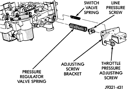
(26) Bend back tabs on boost valve tube brace (Fig. 58).
(27) Remove boost valve connecting tube (Fig. 59). Disengage tube from upper housing port first. Then rock opposite end of tube back and forth to work it out of lower housing.
CAUTION: Do not use tools to loosen or pry the connecting tube out of the valve body housings. Loosen and remove the tube by hand only.
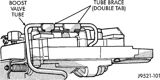
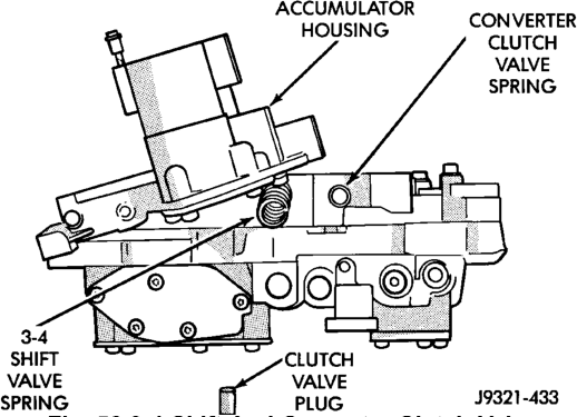
Springs And Plug
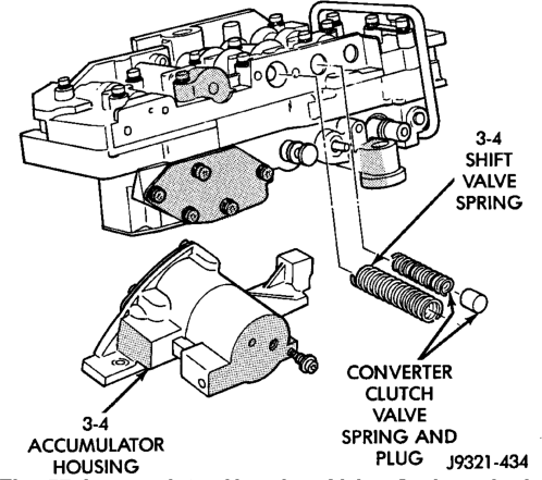
Plug
(28)
Turn valve body over so lower housing is facing

when lower housing and separator plate are removed.
(29) Remove screws attaching valve body lower housing to upper housing and transfer plate (Fig.
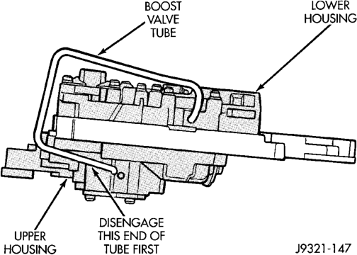
60). Note position of boost valve tube brace for assembly reference.
(30) Remove lower housing and overdrive separator plate from transfer plate (Fig. 60).
(31) Remove the ECE check ball from the transfer plate (Fig. 61). The ECE check ball is approximately 4.8 mm (3/16 in.) in diameter.
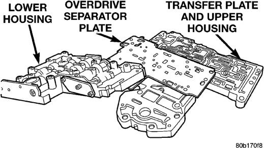
(32) Remove transfer plate from upper housing (Fig. 62).
(33) Turn transfer plate over so upper housing separator plate is facing upward.
(34) Remove upper housing separator plate from transfer plate (Fig. 63). Note position of filter in separator plate for assembly reference.
(35) Remove rear clutch and rear servo check balls from transfer plate. Note check ball location for assembly reference (Fig. 64).
VALVE BODY UPPER HOUSING
(1) Note location of check balls in valve body upper housing (Fig. 65). Then remove the one large diameter and the six smaller diameter check balls.
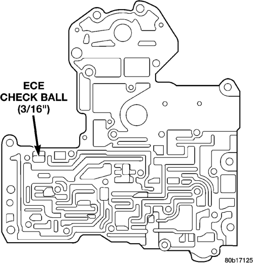
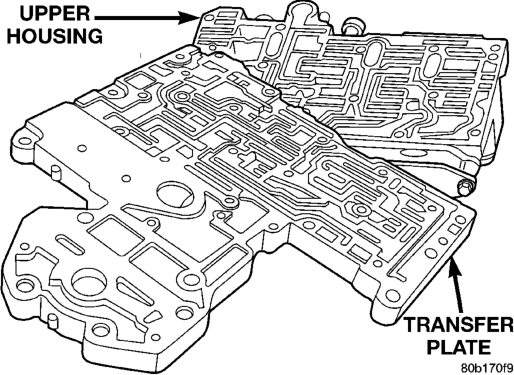
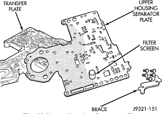
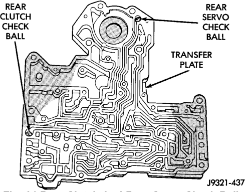
Locations
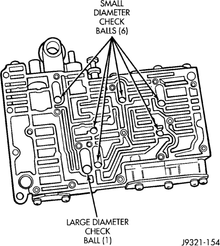
(2) Remove governor plug and shuttle valve covers (Fig. 67).
(3) Remove E-clip that secures shuttle valve secondary spring on valve stem (Fig. 66).
(4) Remove throttle plug, primary spring, shuttle valve, secondary spring, and spring guides (Fig. 67).
(5) Remove boost valve retainer, spring and valve if not previously removed. (6) Remove throttle plug and 1-2 and 2-3 governor plugs (Fig. 54).
(7) Turn upper housing around and remove limit valve and shift valve covers (Fig. 68).
(8) Remove limit valve housing. Then remove retainer, spring, limit valve, and 2-3 throttle plug from limit valve housing (Fig. 68).
(9) Remove 1-2 shift control valve and spring (Fig. 68).
(10) Remove 1-2 shift valve and spring (Fig. 68). (11) Remove 2-3 shift valve and spring from valve body (Fig. 68).
(12) Remove pressure plug cover (Fig. 68). (13) Remove line pressure plug, sleeve, throttle pressure plug and spring (Fig. 68).
VALVE BODY LOWER HOUSING
(1) Remove timing valve cover. (2) Remove 3-4 timing valve and spring.
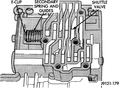
Location
(3) Remove 3-4 quick fill valve, spring and plug. (4) Remove 3-4 shift valve and spring. (5) Remove converter clutch valve, spring and plug (Fig. 69).
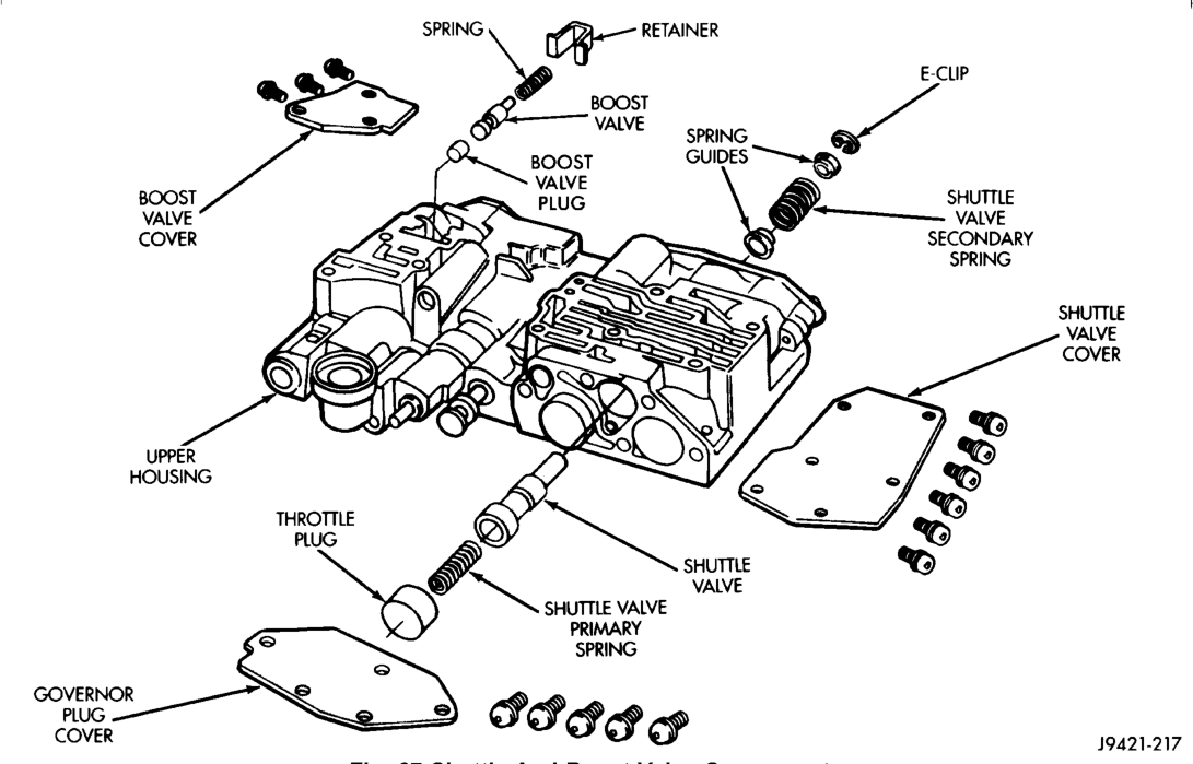
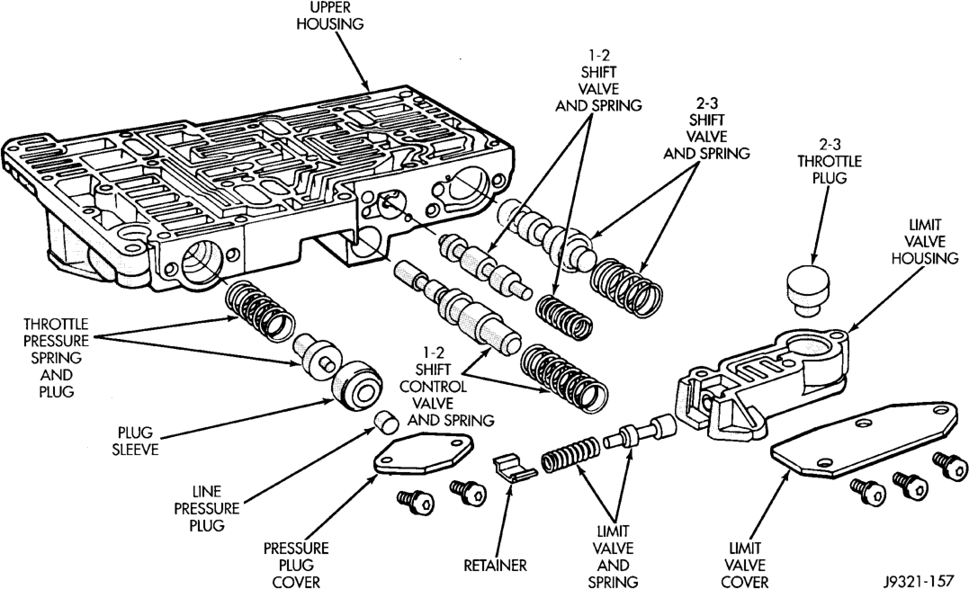
(6) Remove converter clutch timing valve, retainer and valve spring.
3-4 ACCUMULATOR HOUSING
(1) Remove end plate from housing. (2) Remove piston spring. (3) Remove piston. Remove and discard piston seals (Fig. 70).
ASSEMBLY
CAUTION: Do not force valves or plugs into place during reassembly. If the valve body bores, valves and plugs are free of distortion or burrs, the valve body components should all slide into place easily. In addition, do not overtighten the transfer plate and valve body screws during reassembly. Overtightening can distort the housings resulting in valve sticking, cross leakage and unsatisfactory operation. Tighten valve body screws to recommended torque only.
LOWER HOUSING
(1) Lubricate valves, springs, and the housing valve and plug bores with clean transmission fluid (Fig. 69).
(2) Install 3-4 timing valve spring and valve in lower housing.
(3) Install 3-4 quick fill valve in lower housing. (4) Install 3-4 quick fill valve spring and plug in housing.
(5) Install timing valve end plate. Tighten end plate screws to 4 N·m (35 in. lbs.) torque.
3-4 ACCUMULATOR
(1) Lubricate accumulator piston, seals and housing piston bore with clean transmission fluid (Fig. 70).
(2) Install new seal rings on accumulator piston. (3) Install piston and spring in housing. (4) Install end plate on housing.
TRANSFER PLATE
(1) Install rear clutch and rear servo check balls in transfer plate (Fig. 71).
(2) Install filter screen in upper housing separator plate (Fig. 72).
(3) Align and position upper housing separator plate on transfer plate (Fig. 73).
(4) Install brace plate (Fig. 73). Tighten brace attaching screws to 4 N·m (35 in. lbs.) torque.
(5) Install remaining separator plate attaching screws. Tighten screws to 4 N·m (35 in. lbs.) torque.
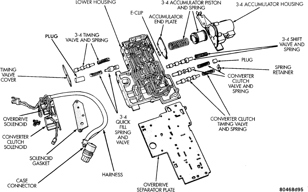
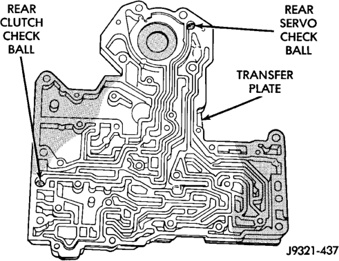
Locations
UPPER AND LOWER HOUSING
(1) Position upper housing so internal passages and check ball seats are facing upward. Then install check balls in housing (Fig. 74). Seven check balls are used. The single large check ball is approximately 8.7 mm (11/32 in.) diameter. The single small check ball is approximately 4.8 mm (3/16 in.) in
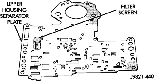
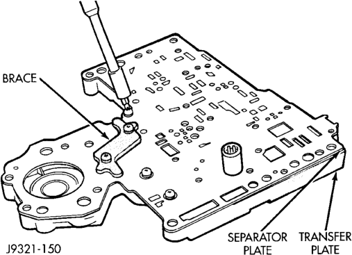
diameter. The remaining 6 check balls are approximately 6.3 mm (1/4 in.) in diameter.
(2) Position assembled transfer plate and upper housing separator plate on upper housing (Fig. 75).
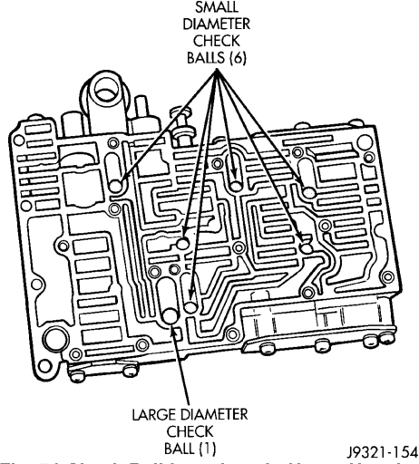
Be sure filter screen is seated in proper housing recess.
(3) Install the ECE check ball into the transfer plate (Fig. 61). The ECE check ball is approximately 4.8 mm (3/16 in.) in diameter.
(4) Position lower housing separator plate on transfer plate (Fig. 76).
(5) Install lower housing on assembled transfer plate and upper housing (Fig. 77).
(6) Install and start all valve body screws by hand except for the screws to hold the boost valve tube brace. Save those screws for later installation. Then tighten screws evenly to 4 N·m (35 in. lbs.) torque. Start at center and work out to sides when tightening screws (Fig. 77).
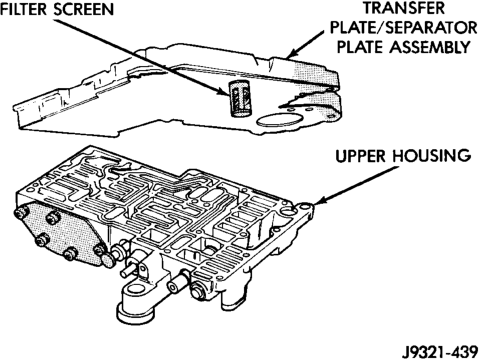
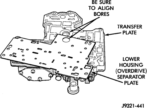
UPPER HOUSING VALVE AND PLUG
Refer to (Fig. 78), (Fig. 79) and (Fig. 80) to perform the following steps.
(1) Lubricate valves, plugs, springs with clean transmission fluid.
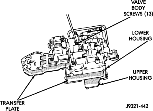
And Upper Housing
(2) Assemble regulator valve line pressure plug, sleeve, throttle plug and spring. Insert assembly in upper housing and install cover plate. Tighten cover plate screws to 4 N·m (35 in. lbs.) torque.
Fig. 78 Shuttle And Boost Valve Components
(3) Install 1-2 and 2-3 shift valves and springs. (4) Install 1-2 shift control valve and spring. (5) Install retainer, spring, limit valve, and 2-3 throttle plug from limit valve housing.
(6) Install limit valve housing and cover plate. Tighten screws to 4 N·m (35 in. lbs.).
(7) Install shuttle valve as follows:
(a) Insert plastic guides in shuttle valve secondary spring and install spring on end of valve.
(b) Install shuttle valve into housing. (c) Hold shuttle valve in place. (d) Compress secondary spring and install E-clip in groove at end of shuttle valve. (e) Verify that spring and E-clip are properly seated before proceeding. (8) Install shuttle valve cover plate. Tighten cover plate screws to 4 N·m (35 in. lbs.) torque.
(9) Install 1-2 and 2-3 valve governor plugs in valve body.
(10) Install shuttle valve primary spring and throttle plug.
(11) Align and install governor plug cover. Tighten cover screws to 4 N·m (35 in. lbs.) torque.

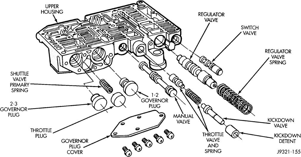

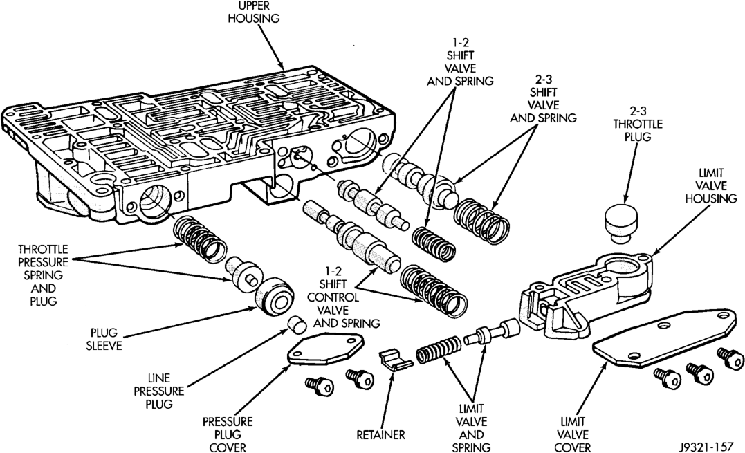

BOOST VALVE TUBE AND BRACE
(1) Position valve body assembly so lower housing is facing upward (Fig. 81). (2) Lubricate tube ends and housing ports with transmission fluid or petroleum jelly.
(3) Start tube in lower housing port first. Then swing tube downward and work opposite end of tube into upper housing port (Fig. 81). (4) Insert and seat each end of tube in housings. (5) Slide tube brace under tube and into alignment with valve body screw holes (Fig. 82).
(6) Install and finger tighten three screws that secure tube brace to valve body housings (Fig. 82).
(7) Bend tube brace tabs up and against tube to hold it in position (Fig. 83).
(8) Tighten all valve body housing screws to 4 N·m (35 in. lbs.) torque after tube and brace are installed. Tighten screws in diagonal pattern starting at center and working outward.
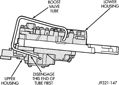
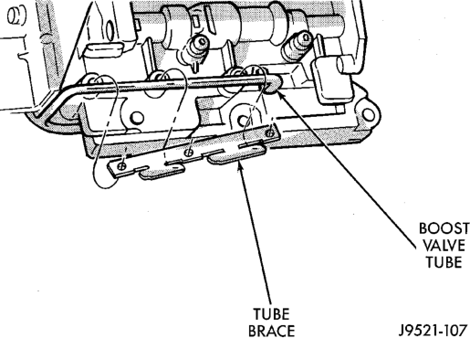
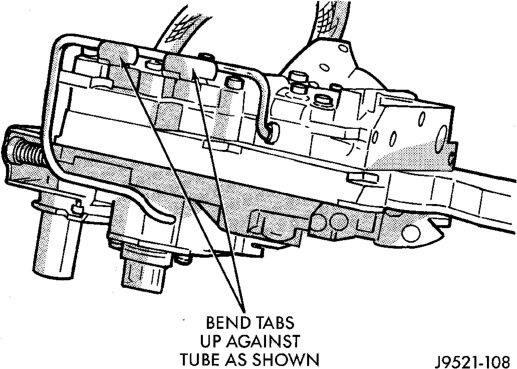
3-4 ACCUMULATOR
(1) Position converter clutch valve and 3-4 shift valve springs in housing (Fig. 84).
(2) Loosely attach accumulator housing with rightside screw (Fig. 84). Install only one screw at this time as accumulator must be free to pivot upward for ease of installation.
(3) Install 3-4 shift valve and spring. (4) Install converter clutch timing valve and spring.
(5) Position plug on end of converter clutch valve spring. Then compress and hold springs and plug in place with fingers of one hand.
(6) Swing accumulator housing upward over valve springs and plug.
(7) Hold accumulator housing firmly in place and install remaining two attaching screws. Be sure springs and clutch valve plug are properly seated (Fig. 85). Tighten screws to 4 N·m (35 in. lbs.).
VALVE BODY FINAL
(1) Install boost valve, valve spring, retainer and cover plate. Tighten cover plate screws to 4 N·m (35 in. lbs.) torque. (2) Insert manual lever detent spring in upper housing.
(3) Position detent ball on end of spring. Then hold detent ball and spring in detent housing with Retainer Tool 6583 (Fig. 86).
(4) Install throttle lever in upper housing. Then install manual lever over throttle lever and start manual lever into housing.
(5) Align manual lever with detent ball and manual valve. Hold throttle lever upward. Then press down on manual lever until fully seated. Remove detent ball retainer tool after lever is seated.
(6) Then install manual lever seal, washer and E-clip.
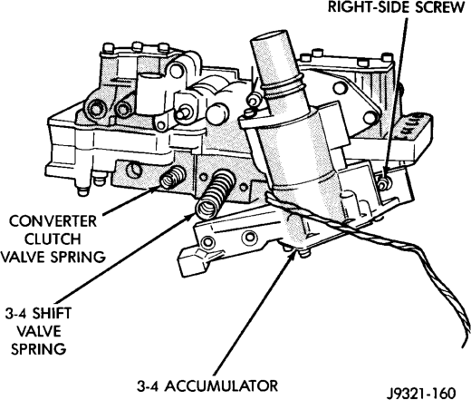
Springs
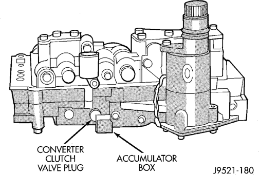
(7) Verify that throttle lever is aligned with end of kickdown valve stem and that manual lever arm is engaged in manual valve (Fig. 87).
(8) Position line pressure adjusting screw in adjusting screw bracket.
(9) Install spring on end of line pressure regulator valve.
(10) Install switch valve spring on tang at end of adjusting screw bracket.
(11) Install manual valve. (12) Install throttle valve and spring. (13) Install kickdown valve and detent. (14) Install pressure regulator valve. (15) Install switch valve. (16) Position adjusting screw bracket on valve body. Align valve springs and press bracket into place. Install short, upper bracket screws first and long bottom screw last. Verify that valve springs and bracket are properly aligned. Then tighten all three bracket screws to 4 N·m (35 in. lbs.) torque.
(17) Lubricate solenoid case connector O-rings and shaft of manual lever with light coat of petroleum jelly.
(18) Obtain new fluid filter for valve body but do not install filter at this time.
(19) If line pressure and/or throttle pressure adjustment screw settings were not disturbed, continue with overhaul or reassembly. However, if adjustment screw settings were moved or changed, readjust as described in Valve Body Control Pressure Adjustment procedure.
(20) Attach solenoid case connector to 3-4 accumulator with shoulder-type screw. Connector has small locating tang that fits in dimple at top of accumulator housing (Fig. 88). Seat tang in dimple before tightening connector screw.
(21) Install solenoid assembly and gasket. Tighten solenoid attaching screws to 8 N·m (72 in. lbs.) torque.
(22) Verify that solenoid wire harness is properly routed (Fig. 89). Solenoid harness must be clear of manual lever and park rod and not be pinched between accumulator housing and cover.
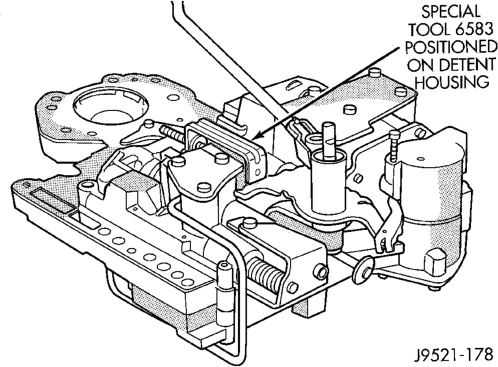
GOVERNOR Body, SENSOR AND SOLENOID
(1) Turn valve body assembly over so accumulator side of transfer plate is facing down.
(2) Install new O-rings on governor pressure solenoid and sensor.
(3) Lubricate solenoid and sensor O-rings with clean transmission fluid.
(4) Install governor pressure sensor in governor body. Then secure sensor with M-shaped retaining clip.
(5) Install governor pressure solenoid in governor body. Push solenoid in until it snaps into place in body.
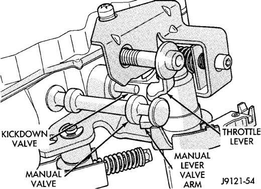
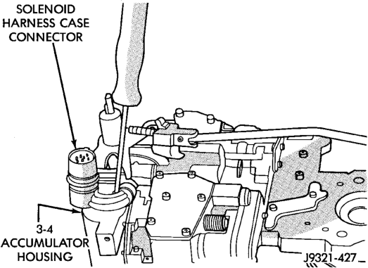
Bolt
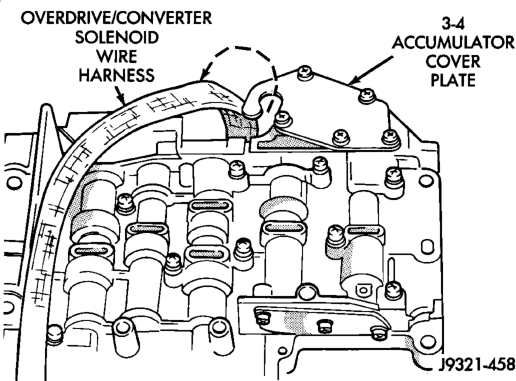
(6) Position governor body gasket on transfer plate.
(7) Install retainer plate on governor body and around solenoid. Be sure solenoid connector is positioned in retainer cutout.
(8) Align screw holes in governor body and transfer plate. Then install and tighten governor body screws to 4 N·m (35 in. lbs.) torque.
(9) Connect harness wires to governor pressure solenoid and governor pressure sensor.
(10) Perform Line Pressure and Throttle Pressure adjustments. Refer to adjustment section of this group for proper procedures.
(11) Install fluid filter and pan. (12) Lower vehicle. (13) Fill transmission with recommended fluid and road test vehicle to verify repair.
TRANSMISSION
DISASSEMBLY
(1) Clean transmission exterior with steam gun or with solvent. Wear eye protection during cleaning operations.
(2) Place transmission in a vertical position. (3)
Measure and record input shaft end play readings.
(4) Remove shift and throttle levers from valve body manual lever shaft.
(5) Place transmission in horizontal position. (6) Remove transmission oil pan and gasket. (7)
Remove filter from valve body (Fig. 90). Keep filter screws separate from other valve body screws. Filter screws are longer and should be kept with filter.
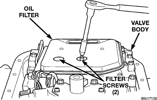
(8) Remove park/neutral position switch. (9)
Remove hex head bolts attaching valve body to transmission case (Fig. 91). A total of 10 bolts are used.
Note different bolt lengths for assembly reference.
(10) Remove valve body assembly. Push valve body harness connector out of case. Then work park rod and valve body out of case (Fig. 92).
(11) Remove accumulator piston and inner and outer springs (Fig. 93).
(12) Remove pump oil seal with suitable pry tool or slide-hammer mounted screw.
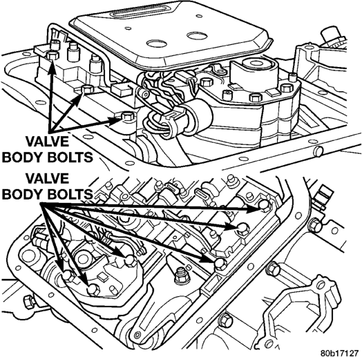
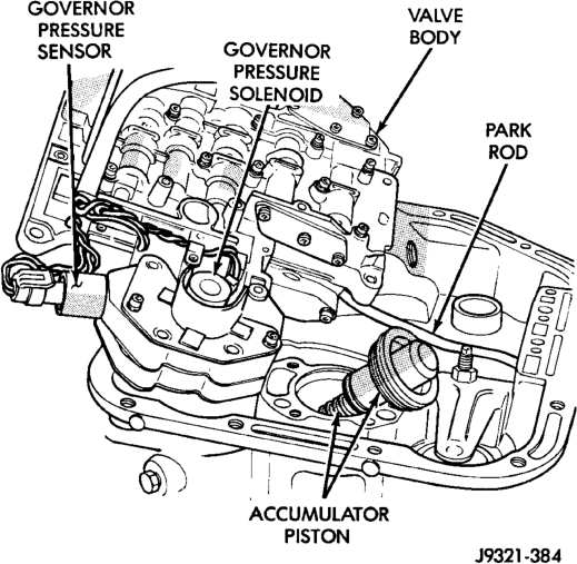
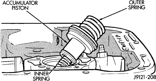
(13) Loosen front band adjusting screw locknut 4-5 turns. Then tighten band adjusting screw until band is tight around front clutch retainer. This prevents front/rear clutches from coming out with pump and possibly damaging clutch or pump components.
(14) Remove oil pump bolts. (15) Thread bolts of Slide Hammer Tools C-3752 into threaded holes in pump body flange (Fig. 94). (16) Bump slide hammer weights outward to remove pump and reaction shaft support assembly from case (Fig. 94).
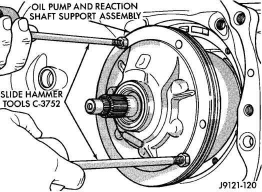
Support Assembly
(17) Loosen front band adjusting screw until band is completely loose. (18) Squeeze front band together and remove band strut (Fig. 95).
(19) Remove front band lever (Fig. 96). (20) Remove front band lever shaft plug, if necessary, from converter housing.
(21) Remove front band lever shaft. (22) Remove front and rear clutch units as assembly. Grasp input shaft, hold clutch units together and remove them from case (Fig. 97).
(23) Lift front clutch off rear clutch (Fig. 98). Set clutch units aside for overhaul.
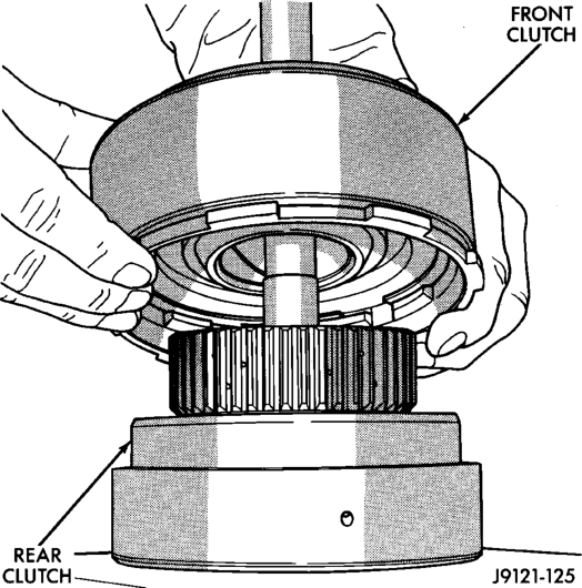
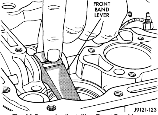
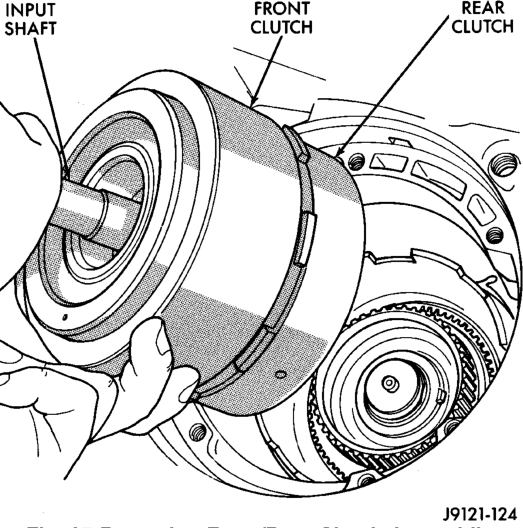
(24) Remove intermediate shaft thrust washer from front end of shaft or from rear clutch hub (Fig. 99).
(25) Remove output shaft thrust plate from intermediate shaft hub (Fig. 100).
(26) Slide front band off driving shell (Fig. 101) and remove band from case.
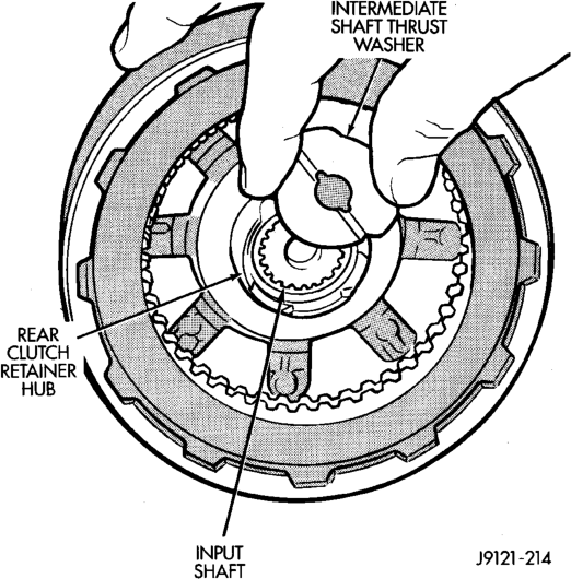
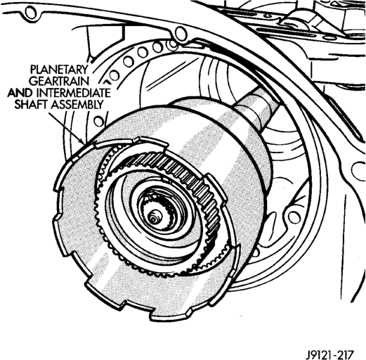
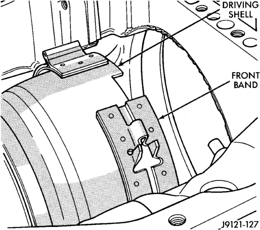
(27) Remove planetary geartrain as assembly (Fig. 102). Support geartrain with both hands during removal. Do not allow machined surfaces on intermediate shaft or overdrive piston retainer to become nicked or scratched.
(28) If overdrive unit is not to be serviced, install Alignment Shaft 6227-2 into the overdrive unit to prevent misalignment of the overdrive clutches during service of main transmission components. (29) Loosen rear band adjusting screw 4-5 turns. (30) Remove low-reverse drum snap ring (Fig. 103).
(31) Remove low-reverse drum and reverse band. (32) Remove overrunning clutch roller and spring assembly as a unit (Fig. 104).
Intermediate Shaft Assembly
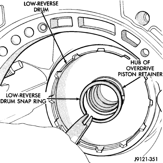
(33) Compress front servo rod guide about 1/8 inch with Valve Spring Compressor C-3422-B (Fig. 105).
(34) Remove front servo rod guide snap ring. Exercise caution when removing snap ring. Servo bore can be scratched or nicked if care is not exercised.
(35) Remove compressor tools and remove front servo rod guide, spring and servo piston.
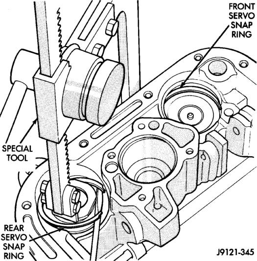
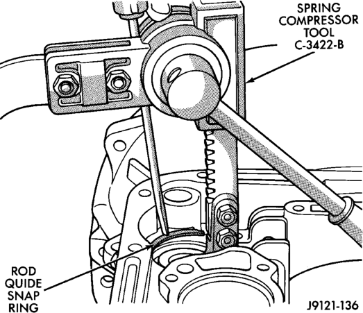
(36) Compress rear servo spring retainer about 1/16 inch with Valve Spring Compressor C-3422-B (Fig. 106).
(37) Remove rear servo spring retainer snap ring. Then remove compressor tools and remove rear servo spring and piston.
(38) Inspect transmission components.
NOTE: TO SERVICE THE OVERRUNNING CLUTCH CAM OR OVERDRIVE PISTON RETAINER, REFER TO OVERRUNNING CLUTCH CAM SERVICE IN THIS SECTION.
ASSEMBLY
Do not allow dirt, grease, or foreign material to enter the case or transmission components during assembly. Keep the transmission case and components clean. Also make sure the tools and workbench area used for assembly operations are equally clean.
Shop towels used for wiping off tools and hands must be made from lint free material. Lint will stick to transmission parts and could interfere with valve operation, or even restrict fluid passages.
Lubricate the transmission components with Mopart transmission fluid during reassembly. Use Mopart Door Ease, or Ru-Glyde on seals and O-rings to ease installation.
Petroleum jelly can also be used to hold thrust washers, thrust plates and gaskets in position during assembly. However, do not use chassis grease, bearing grease, white grease, or similar lubricants on any transmission part. These types of lubricants can eventually block or restrict fluid passages and interfere with valve operation. Use petroleum jelly only.
Do not force parts into place. The transmission components and subassemblies are easily installed by hand when properly aligned.
If a part seems extremely difficult to install, it is either misaligned or incorrectly assembled. Also verify that thrust washers, thrust plates and seal rings are correctly positioned before assembly. These parts can interfere with proper assembly if mis-positioned.
The planetary geartrain, front/rear clutch assemblies and oil pump are all much easier to install when the transmission case is upright.
(1) Install rear servo piston, spring and retainer (Fig. 107). Install spring on top of servo piston and install retainer on top of spring. (2) Install front servo piston assembly, servo spring and rod guide (Fig. 108).
(3) Compress front/rear servo springs with Valve Spring Compressor C-3422-B and install each servo snap ring (Fig. 109).
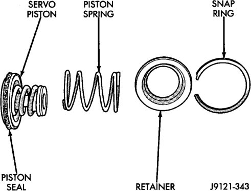
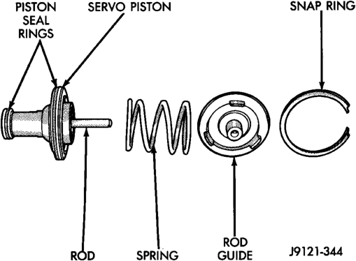
(4) Lubricate clutch cam rollers with transmission fluid.
(5) Install rear band in case (Fig. 110). Be sure twin lugs on band are seated against reaction pin.
(6) Install low-reverse drum and check overrunning clutch operation as follows:
(a) Lubricate overrunning clutch race (on drum hub) with transmission fluid.
(b) Guide drum through rear band. (c) Tilt drum slightly and start race (on drum hub) into overrunning clutch rollers.
(d) Press drum rearward and turn it in clockwise direction until drum seats in overrunning clutch (Fig. 111).
(e) Turn drum back and forth. Drum should rotate freely in clockwise direction and lock
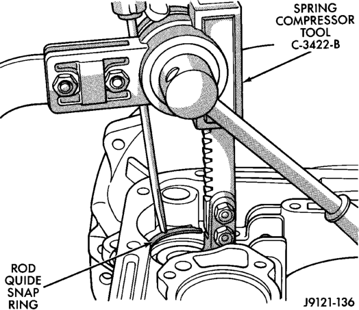
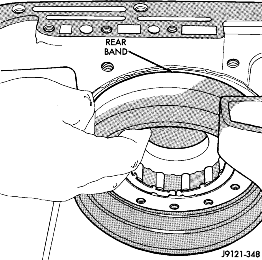
in counterclockwise direction (as viewed from front of case). (7) Install snap ring that secures low-reverse drum to hub of overdrive piston retainer (Fig. 112).
(8) Install rear band lever and pivot pin (Fig. 113). Align lever with pin bores in case and push pivot pin into place. (9) Install planetary geartrain assembly (Fig. 114). (10) Install thrust plate on intermediate shaft hub (Fig. 115). Use petroleum jelly to hold thrust plate in place.
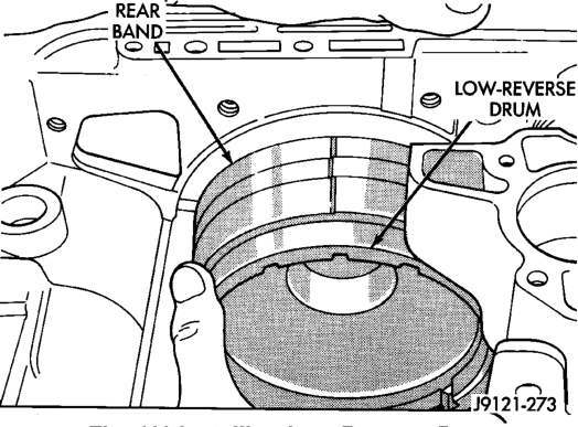
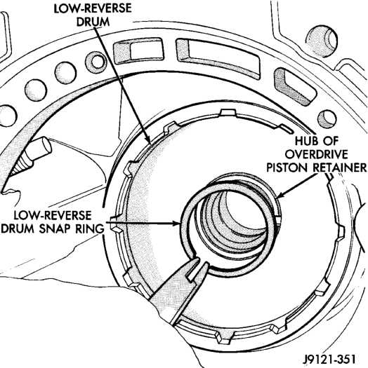
Snap Ring
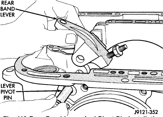
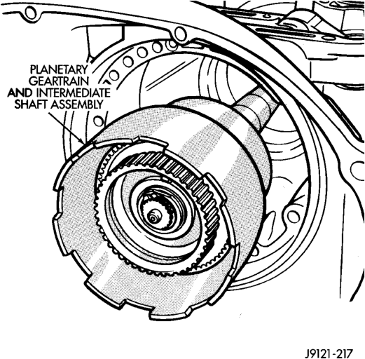
(11) Check seal ring on rear clutch retainer hub and seal rings on input shaft (Fig. 116). Also verify that shaft seal rings are installed in sequence shown.
(12) Install rear clutch thrust washer (Fig. 117). Use additional petroleum jelly to hold washer in
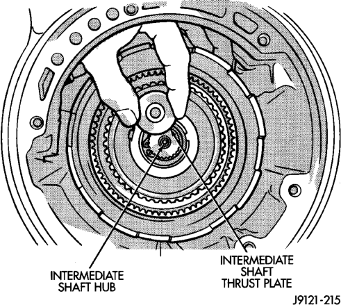
place if necessary.
(13) Align clutch discs in front clutch and install front clutch on rear clutch (Fig. 118). Rotate front clutch retainer back and forth until completely seated on rear clutch retainer.
(14) Coat intermediate shaft thrust washer with petroleum jelly. Then install washer in rear clutch hub (Fig. 119). Use enough petroleum jelly to hold
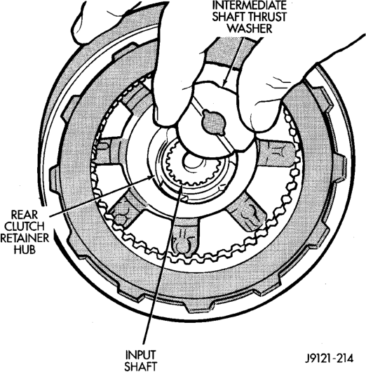
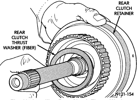
washer in place. Be sure grooved side of washer faces rearward (toward output shaft) as shown. Also note that washer only fits one way in clutch hub. Note thickness of this washer. It is a select fit part and is used to control transmission end play.
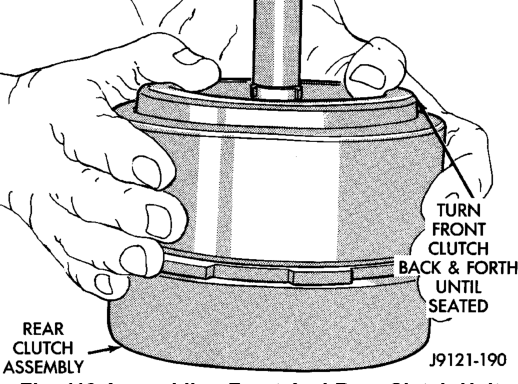
(15) Align drive teeth on rear clutch discs with small screwdriver (Fig. 120). This makes installation on front planetary easier.
(16) Raise front end of transmission upward as far as possible and support case with wood blocks. Front/ rear clutch and oil pump assemblies are easier to install if transmission is as close to upright position as possible.
(17) Slide front band into case. (18) Install front and rear clutch units as assembly (Fig. 121). Align rear clutch with front annulus gear and install assembly in driving shell. Be sure output shaft thrust washer and thrust plate are not displaced during installation.
(19) Carefully work assembled clutches back and forth to engage and seat rear clutch discs on front annulus gear. Also be sure front clutch drive lugs are fully engaged in slots of driving shell after installation.
(20) Assemble front band strut. (21) Install front band adjuster, strut and adjusting screw (Fig. 122). (22) Tighten band adjusting screw until band just grips clutch retainer. Verify that front/rear clutches are still seated before continuing.
(23) Check seal rings on reaction shaft support hub. Verify that seal rings are hooked together and that front clutch thrust washer is properly positioned (Fig. 123). Use petroleum jelly to hold thrust washer in place if necessary. (24) Lubricate oil pump body seal with petroleum jelly. Lubricate pump shaft seal lip with petroleum jelly.