Transmission and Transfer Case — part 4 of 6 — 1998 Jeep Grand Cherokee ZJ Export Service Manual
Pages 1556–1615 · 60 pages · 30 words repaired
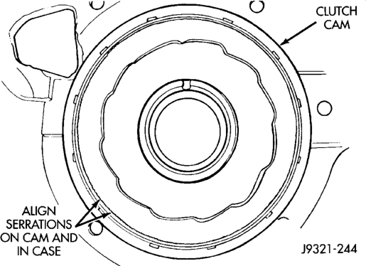
cam ramps should be to left when cam is viewed from front end of case (Fig. 149).
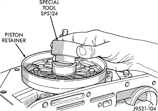
(4) Insert Adapter Tool SP-5124 into piston retainer (Fig. 150).
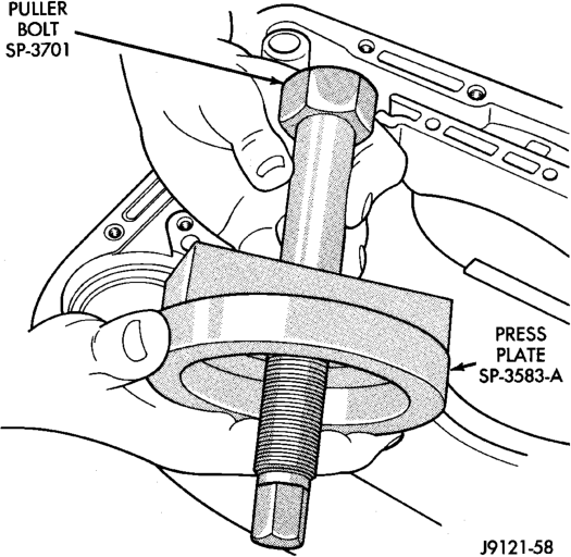
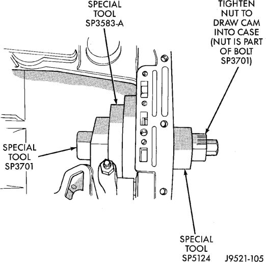
(5) Assemble Puller Bolt SP-3701 and Press Plate SP-3583-A (Fig. 151).
Case
(6) Install assembled puller plate and bolt (Fig. 152). Insert bolt through cam, case and adapter tool. Be sure plate is seated squarely on cam.
(7) Hold puller plate and bolt in place and install puller nut SP-3701 on puller bolt (Fig. 153).
(8) Tighten puller nut to press clutch cam into case (Fig. 153). Be sure cam is pressed into case evenly and does not become cocked.
(9) Remove clutch cam installer tools. (10) Stake case in 12 places around clutch cam to help secure cam in case. Use blunt punch or chisel to stake case.
Piston Retainer
Press Plate
(11) Remove piston retainer from case. Cover retainer with plastic sheeting, or paper to keep it dust free.
(12) Clean case and cam thoroughly. Be sure any chips/shavings generated during cam installation are removed from case.
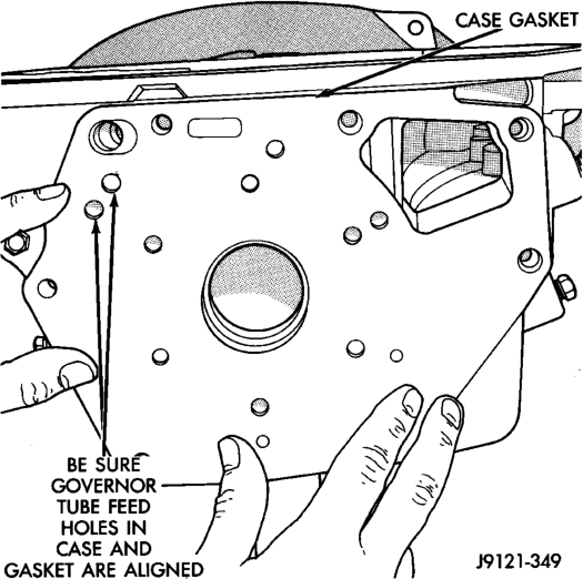
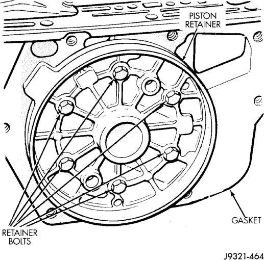
(13) Install new gasket at rear of transmission case. Use petroleum jelly to hold gasket in place. Be sure to align governor feed holes in gasket with feed passages in case (Fig. 154). Also install gasket before overdrive piston retainer. Center hole in gasket is smaller than retainer and cannot be installed over retainer.
Case
(14) Position overdrive piston retainer on transmission case and align bolt holes in retainer, gasket and case (Fig. 155). Then install and tighten retainer bolts to 17 N·m (13 ft. lbs.) torque.
(15) Install new seals on overdrive piston. (16) Stand transmission case upright on bellhousing. (17) Position Guide Ring 8114-1 on outer edge of overdrive piston retainer.
(18) Position Seal Guide 8114-3 on inner edge of overdrive piston retainer.
(19) Install overdrive piston in overdrive piston retainer by: aligning locating lugs on overdrive piston to the two mating holes in retainer.
(a) Aligning locating lugs on overdrive piston to the two mating holes in retainer.
(b) Lubricate overdrive piston seals with Mopart Door Ease, or equivalent.
(c) Install piston over Seal Guide 8114–3 and inside Guide Ring 8114–1. (d) Push overdrive piston into position in retainer.
(e) Verify that the locating lugs entered the lug bores in the retainer.
NOTE: INSTALL THE REMAINING TRANSMISSION COMPONENTS AND OVERDRIVE UNIT.
FRONT SERVO PISTON
DISASSEMBLY
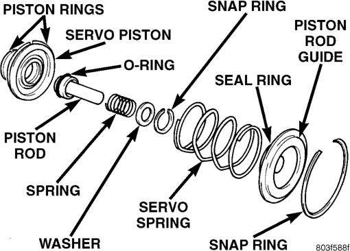
(1) Remove seal ring from rod guide (Fig. 156). (2)
Remove small snap ring from servo piston rod.
Then remove piston rod, spring and washer from piston.
(3) Remove and discard servo component O-ring and seal rings.
ASSEMBLY
Clean and inspect front servo components. (1) Lubricate new O-ring and seal rings with petroleum jelly and install them on piston, guide and rod.
(2) Install rod in piston. Install spring and washer on rod. Compress spring and install snap ring (Fig. 156).
REAR SERVO PISTON
DISASSEMBLY
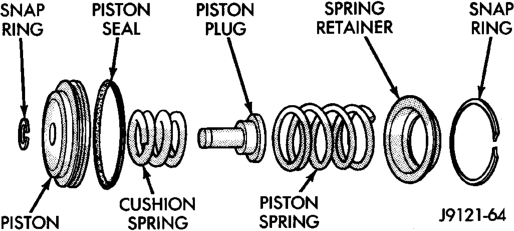
(1) Remove small snap ring and remove plug and spring from servo piston (Fig. 157).
(2) Remove and discard servo piston seal ring.
ASSEMBLY
(1) Lubricate piston and guide seals with petroleum jelly. Lubricate other servo parts with Mopart ATF Plus 3, Type 7176, transmission fluid.
(2) Install new seal ring on servo piston. (3)
Assemble piston, plug, spring and new snap ring.
(4) Lubricate piston seal lip with petroleum jelly.
OIL PUMP AND REACTION SHAFT SUPPORT
DISASSEMBLY
(1) Mark position of support in oil pump body for assembly alignment reference. Use scriber or paint to make alignment marks.
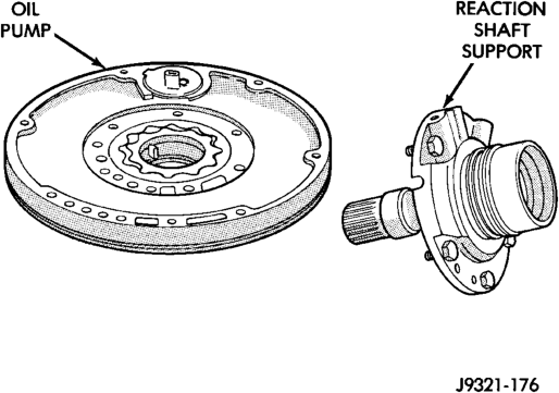
(2) Place pump body on two wood blocks. (3) Remove reaction shaft support bolts and separate support from pump body (Fig. 158).
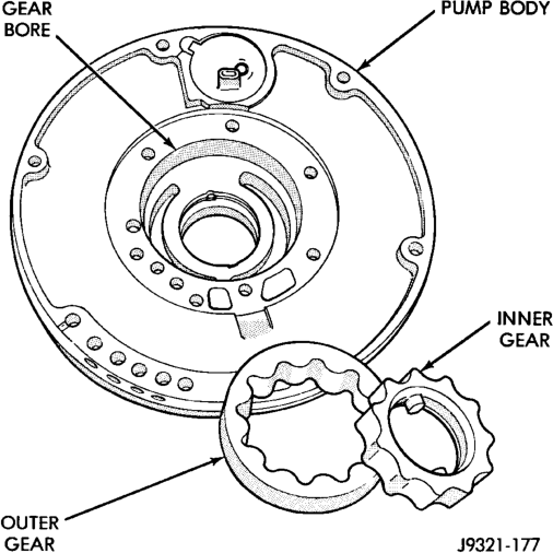
(4) Remove pump inner and outer gears (Fig. 159). (5) Remove O-ring seal from pump body (Fig. 160). Discard seal after removal.
(6) Remove oil pump seal with Remover Tool C-3981. Discard seal after removal.
OIL PUMP BUSHING REMOVAL
(1) Position pump housing on clean, smooth surface with gear cavity facing down.
(2) Remove bushing with Tool Handle C-4171 and Bushing Remover SP-3550 (Fig. 161).
REACTION SHAFT SUPPORT BUSHING REMOVAL
(1) Assemble Cup Tool SP-3633, Nut SP-1191 and Bushing Remover SP-5301 (Fig. 163).
(2) Hold cup tool firmly against reaction shaft. Thread remover tool into bushing as far as possible by hand.

(3) Using wrench, thread remover tool an additional 3-4 turns into bushing to firmly engage tool.
(4) Tighten tool hex nut against cup tool to pull bushing from shaft. Clean all chips from shaft and support after bushing removal.
ASSEMBLY
OIL PUMP BUSHING INSTALLATION
(1) Assemble Tool Handle C-4171 and Bushing Installer SP-5118.
(2) Place bushing on installer tool and start bushing into shaft. (3) Tap bushing into place until Installer Tool SP-5118 bottoms in pump cavity. Keep tool and bushing square with bore. Do not allow bushing to become cocked during installation.
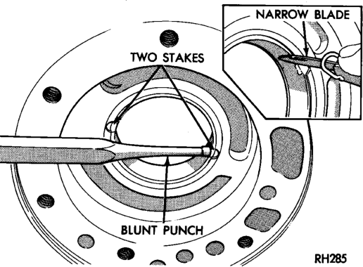
(4) Stake pump bushing in two places with blunt punch. Remove burrs from stake points with knife blade (Fig. 162).
REACTION SHAFT SUPPORT BUSHING INSTALLATION
(1) Place reaction shaft support upright on a clean, smooth surface.
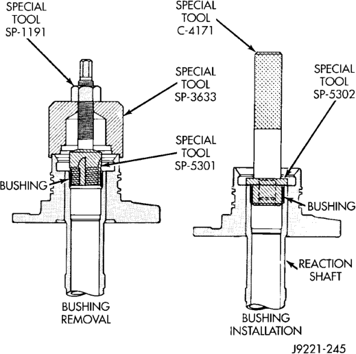
(2) Assemble Bushing Installer Tools C-4171 and SP-5302. Then slide new bushing onto installer tool (Fig. 163).
(3) Start bushing in shaft. Tap bushing into shaft until installer tool bottoms against support flange.
(4) Clean reaction shaft support thoroughly after bushing replacement (to remove any chips).
(1) Lubricate pump gears with transmission fluid and install them in pump body.
(2) Install thrust washer on reaction shaft support hub. Lubricate washer with petroleum jelly or transmission fluid before installation.
(3) If reaction shaft seal rings are being replaced, install new seal rings on support hub. Lubricate seal rings with transmission fluid or petroleum jelly after
installation. Squeeze each ring until ring ends are securely hooked together.
CAUTION: The reaction shaft support seal rings will break if overspread, or twisted. If new rings are being installed, spread them only enough for installation. Also be very sure the ring ends are securely hooked together after installation. Otherwise, the rings will either prevent pump installation, or break during installation.
(4) Align and install reaction shaft support on pump body.
(5) Install bolts attaching reaction shaft support to pump. Tighten bolts to 20 N·m (175 in. lbs.) torque.
(6) Install new pump seal with Installer Tool C-3860-A (Fig. 164). Use hammer or mallet to tap seal into place.
(7) Install new O-ring on pump body. Lubricate oil seal and O-ring with petroleum jelly.
(8) Cover pump assembly to prevent dust entry and set aside for assembly installation.
FRONT CLUTCH
DISASSEMBLY
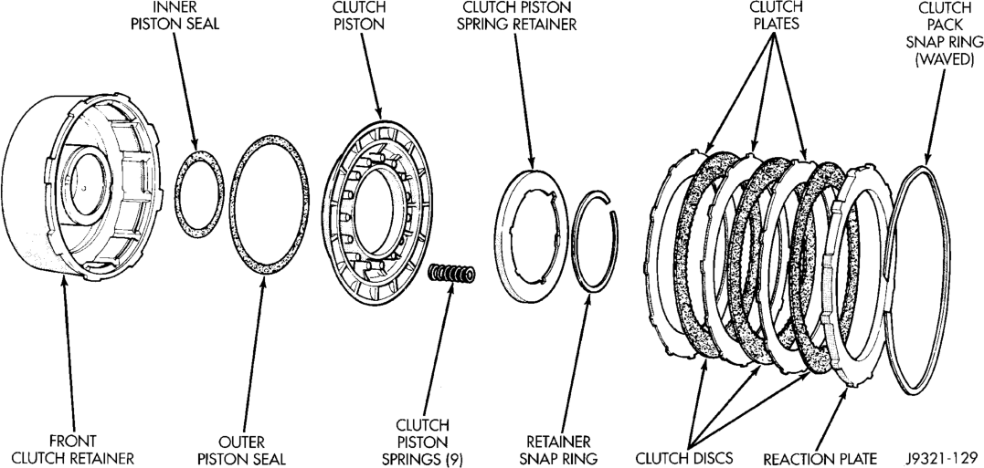
(1) Remove waved snap ring and remove reaction plate, clutch plates and clutch discs.
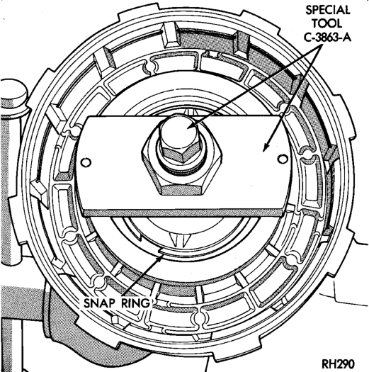
(2) Compress clutch piston retainer and piston springs with Compressor Tool C-3863-A (Fig. 165).
(3) Remove retainer snap ring and remove compressor tool.

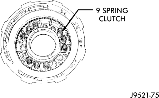
(4) Remove clutch piston springs (Fig. 166). Note position of piston springs for assembly reference.
(5) Remove clutch piston from retainer with a twisting motion.
(6) Remove and discard clutch piston inner and outer seals.
Snap Ring
(7) Assemble Tool Handle C-4171 and Bushing Remover SP-3629 (Fig. 167).
(8) Insert remover tool in bushing and drive bushing straight out of clutch retainer.
ASSEMBLY
(1) Mount Bushing Installer SP-5511 on tool handle (Fig. 167).
(2) Slide new bushing onto installer tool and start bushing into retainer.
(3) Tap new bushing into place until installer tool bottoms against clutch retainer.
(4) Remove installer tools and clean retainer thoroughly.
(5) Soak clutch discs in transmission fluid. (6) Install new inner and outer seals on clutch piston. Be sure seal lips face interior of retainer.
(7) Lubricate new inner and outer piston seals with Ru-Glyde, or Mopart Door Ease.
(8) Install clutch piston in retainer. Use twisting motion to seat piston in bottom of retainer. A thin strip of plastic (about 0.015 - 0.020 in. thick), can be used to guide seals into place if necessary.
CAUTION: Never push the clutch piston straight in. This will fold the seals over causing leakage and clutch slip. In addition, never use any type of metal tool to help ease the piston seals into place. Metal tools will cut, shave, or score the seals.
(9) Install and position nine clutch piston springs (Fig. 168).
(10) Install spring retainer on top of piston springs.
(11) Compress spring retainer and piston springs with Tool C-3863-A.
(12) Install spring retainer snap ring and remove compressor tool.
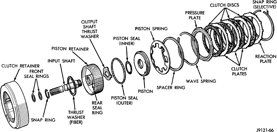
(13) Install clutch plates and discs (Fig. 166). Three clutch discs, three steel plates and one reaction plate are required.
(14) Install reaction plate followed by waved snap ring.
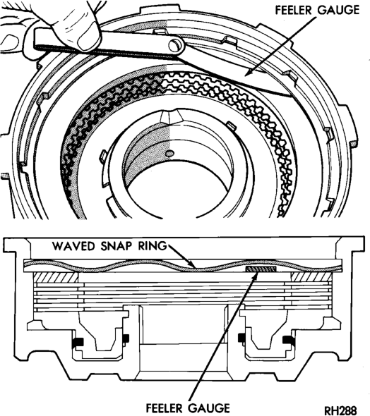
(15) Check clutch pack clearance with feeler gauge (Fig. 169). Clearance between waved spring and pressure plate should 1.78 - 3.28 mm (0.070 - 0.129 in.). If clearance is incorrect, clutch plates, clutch discs, snap ring, or pressure plate may have to be changed.
REAR CLUTCH
DISASSEMBLY
(1) Remove clutch pack select fit snap ring. (2) Remove reaction plate and remove clutch plates and discs (Fig. 170).
(3) Remove pressure plate, wave spring, spacer ring and piston spring from clutch retainer.
(4) Remove clutch piston from piston retainer with a twisting motion.
(5) Remove input shaft thrust washer, if washer remained in piston retainer hub during removal.
Fig. 166 Front Clutch Components
Replacement Tools
(6) Remove seals from clutch piston. Discard seals after removal.
If the input shaft must be replaced, first remove the retaining ring that secures the shaft in the piston retainer hub. Then press the old shaft out of the retainer with a shop press using suitable press tools to press on the shaft and to support the retainer hub as close to the shaft as possible.
ASSEMBLY
(1) Lubricate the splines of the new shaft with petroleum jelly or Mopart ATF Plus 3, type 7176. Then align the shaft in the piston retainer and carefully press it into place using suitable press tools to press the shaft and to support the retainer hub as close to the shaft as possible. Do not allow the shaft to become cocked during installation. The retainer can be cracked if misalignment occurs.
(2) Install the shaft retaining ring after pressing the shaft into place. Be sure the ring is fully seated before proceeding with clutch assembly.
(3) Invert the input shaft in the press and using the same tools as in removal, press on shaft enough to seat the snap-ring into the retainer.
(4) Soak clutch discs in transmission fluid before assembly.
Pack Clearance
(5) Install new seals on clutch piston. Lubricate piston seals with Mopart Door Ease, or Ru-Glyde to ease installation. Be sure seal lips face input shaft.
(6) Install clutch piston in retainer. Use twisting motion to seat piston in bottom of retainer. A thin strip of plastic (about 0.0209 thick), can be used to guide seals into place if necessary.
CAUTION: Never push the clutch piston straight in. This will fold the seals over causing leakage and clutch slip. In addition, never use any type of metal tool to help ease the piston seals into place. Metal tools will cut, shave, or score the seals.
(7) Assemble piston retainer and clutch retainer. (8) Support clutch retainer with wood blocks, or insert input shaft through pre-drilled hole in workbench. Clutch pack components are easier to install if retainers are properly supported.
(9) Install piston spring in clutch retainer. Concave side of spring faces upward and away from clutch piston.
(10) Install spacer ring on top of piston spring. (11) Install wave spring on top of spacer ring. Then seat wave spring in retainer groove. If wave spring will not seat properly, spacer ring has probably shifted over and into wave spring groove in retainer. Use small screwdriver to realign spacer ring if necessary.
(12) Install inner pressure plate in clutch retainer. (13) Install first clutch disc followed by steel plate until all discs and plates are installed. 4 clutch discs and steel plates are required (Fig. 170).
(14) Install reaction plate on top of last clutch disc. (15) Install selective snap ring to secure clutch pack in retainer.
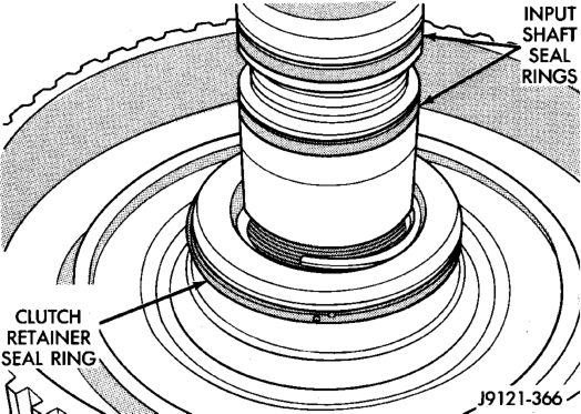
(16) Install new seal rings on input shaft if necessary (Fig. 171). Be very sure ring ends are all securely hooked together before proceeding.
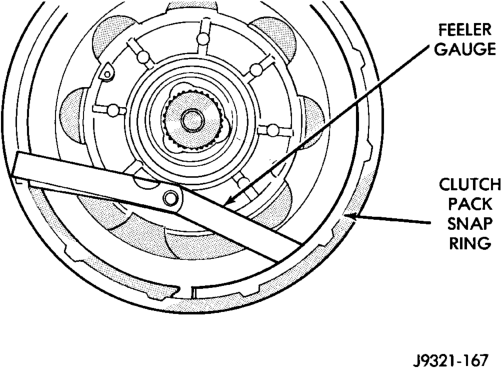
(17) Check clutch pack clearance with feeler gauge (Fig. 172). Clearance should be 0.63 to 1.14 mm (0.025 to 0.045 in.).
(18) If clutch pack clearance is incorrect, clutch pack snap ring, may have to be replaced.
(19) Install thrust washer on piston retainer hub. Use petroleum jelly to hold thrust washer in place.
PLANETARY GEARTRAIN/OUTPUT SHAFT
DISASSEMBLY
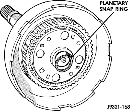
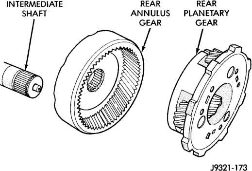
(1) Remove planetary snap ring from intermediate shaft (Fig. 173). Discard snap ring as it is not reusable.
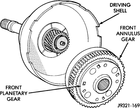
(2) Remove front planetary gear and front annulus gear as assembly (Fig. 174).
(3) Remove front planetary gear and thrust washer from front annulus gear (Fig. 175). Note thrust washer position for assembly reference.
(4) Remove tabbed thrust washer from driving shell (Fig. 176). Note washer position for assembly reference.
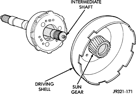
(5) Remove sun gear and driving shell as assembly (Fig. 177).
Annulus Gears
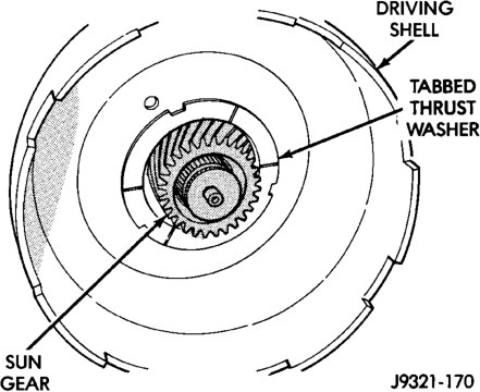
(6) Remove tabbed thrust washer from rear planetary gear (Fig. 178). Note washer position on gear for assembly reference.
(7) Remove rear planetary gear and rear annulus gear from intermediate shaft (Fig. 179).
(8) Remove thrust plate from rear annulus gear (Fig. 180).
ASSEMBLY
(1) Lubricate sun gear and planetary gears with transmission fluid during assembly. Use petroleum jelly to lubricate intermediate shaft bushing surfaces, thrust washers and thrust plates and to hold these parts in place during assembly.
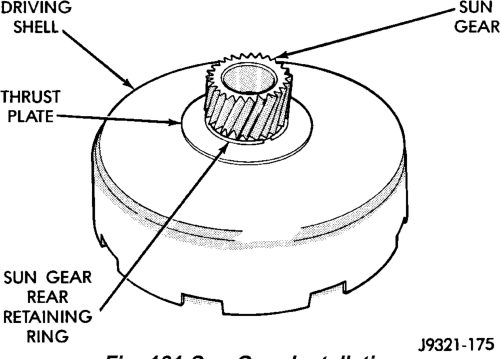
(2) Install front snap ring on sun gear and install gear in driving shell. Then install thrust plate over
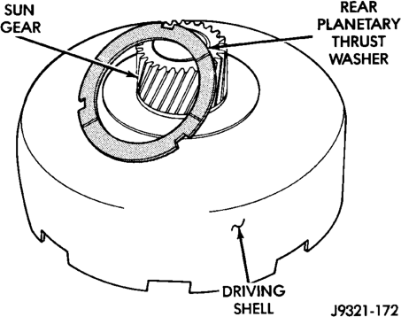
sun gear and against rear side of driving shell (Fig. 181). Install rear snap ring to secure sun gear and thrust plate in driving shell.
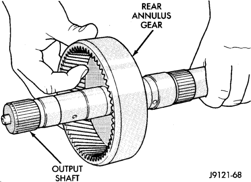
(3) Install rear annulus gear on intermediate shaft (Fig. 182).
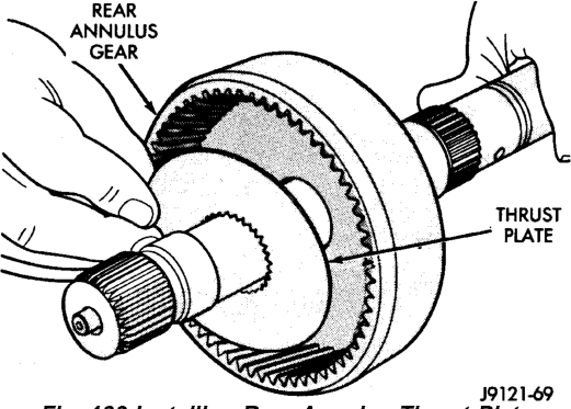
Install thrust plate in annulus gear (Fig. 183). Be
(4)
sure plate is seated on shaft splines and against gear.
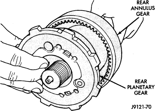
(5) Install rear planetary gear in rear annulus gear (Fig. 184). Be sure planetary carrier is seated against annulus gear.
Intermediate Shaft
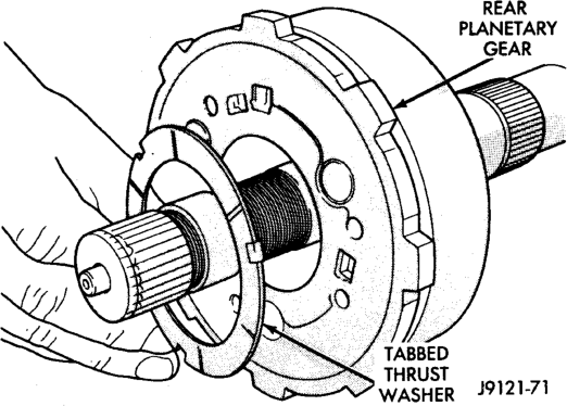
(6) Install tabbed thrust washer on front face of rear planetary gear (Fig. 185). Seat washer tabs in matching slots in face of gear carrier. Use extra petroleum jelly to hold washer in place if desired.
(7) Lubricate sun gear bushings with petroleum jelly or transmission fluid.
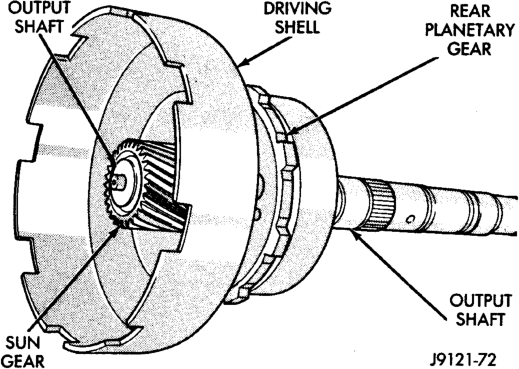
(8) Install sun gear and driving shell on intermediate shaft (Fig. 186). Seat shell against rear planetary gear. Verify that thrust washer on planetary gear was not displaced during installation.
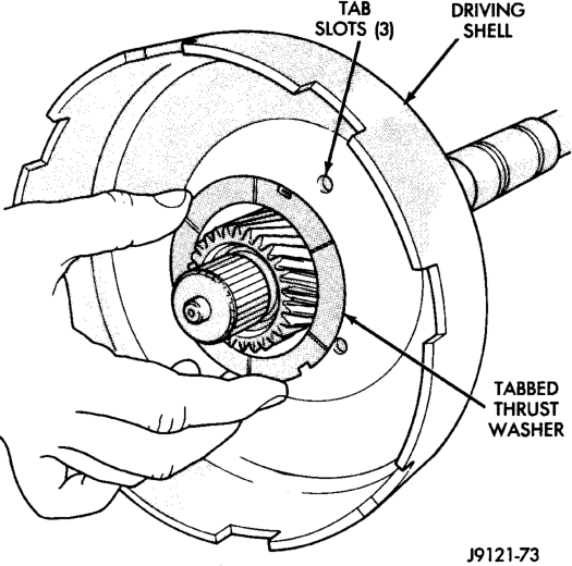
(9) Install tabbed thrust washer in driving shell (Fig. 187), be sure washer tabs are seated in tab slots of driving shell. Use extra petroleum jelly to hold washer in place if desired.
(10) Install tabbed thrust washer on front planetary gear (Fig. 188). Seat washer tabs in matching slots in face of gear carrier. Use extra petroleum jelly to hold washer in place if desired.
(11) Install front annulus gear over and onto front planetary gear (Fig. 189). Be sure gears are fully meshed and seated.
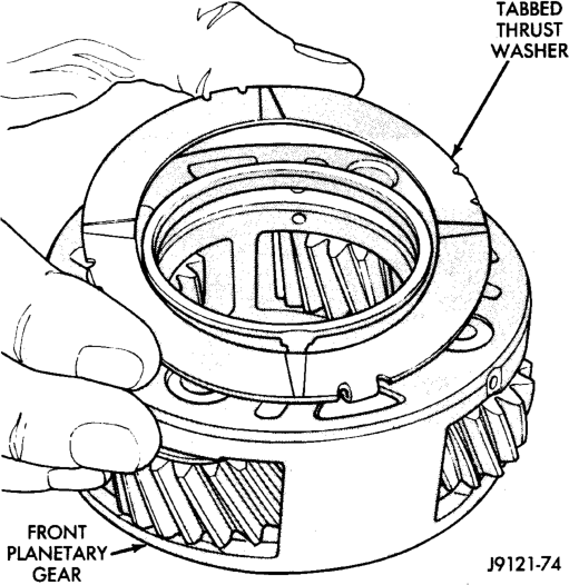
Planetary Gear
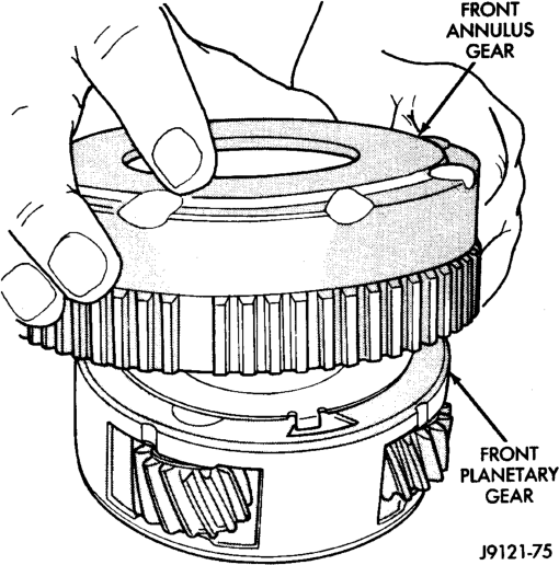
Gears
(12) Install front planetary and annulus gear assembly (Fig. 190). Hold gears together and slide them onto shaft. Be sure planetary pinions are seated on sun gear and that planetary carrier is seated on intermediate shaft.
(13) Place geartrain in upright position. Rotate gears to be sure all components are seated and properly assembled. Snap ring groove at forward end of intermediate shaft will be completely exposed when components are assembled correctly.
(14) Install new planetary snap ring in groove at end of intermediate shaft (Fig. 191).
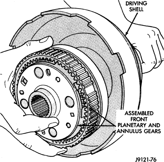
Gear Assembly
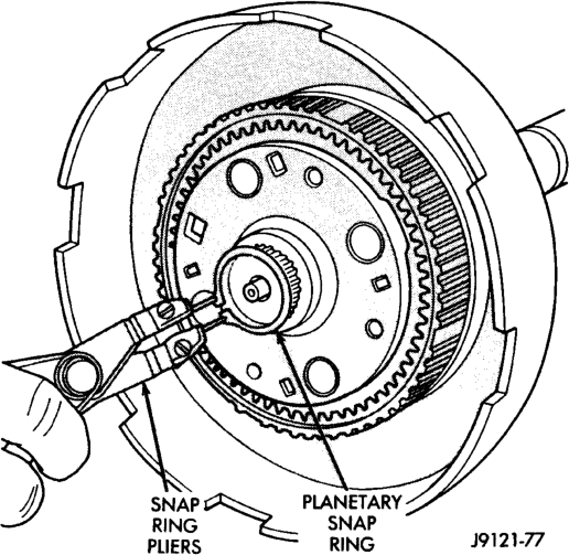
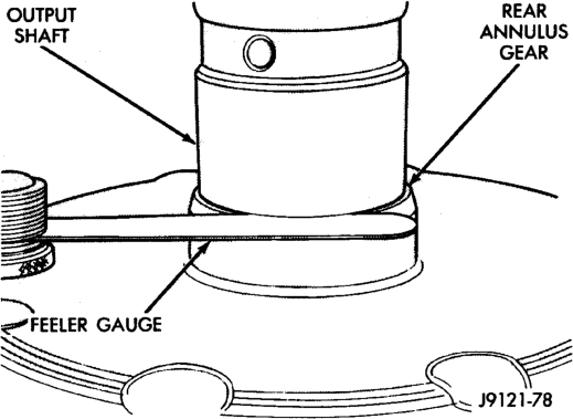
(15) Turn planetary geartrain over. Position wood block under front end of intermediate shaft and support geartrain on shaft. Be sure all geartrain parts have moved forwrd against planetary snap ring. This is important for accurate end play check. (16) Check planetary geartrain end play with feeler gauge (Fig. 192). Insert gauge between rear annulus gear and shoulder on intermediate shaft as shown. End play should be 0.15 to 1.22 mm (0.006 to 0.048 in.).
(17) If end play is incorrect, install thinner/thicker planetary snap ring as needed.
OVERDRIVE UNIT
DISASSEMBLY
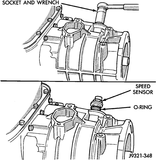
(1) Remove transmission speed sensor and O-ring seal from overdrive case (Fig. 193).
Installation
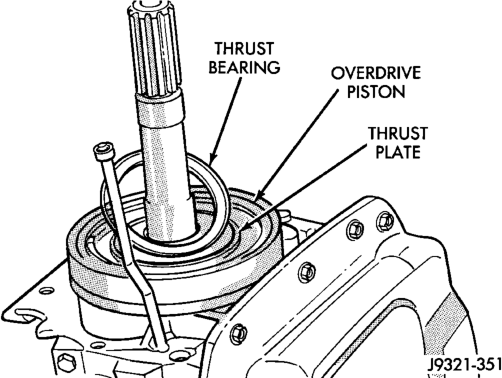
(2) Remove overdrive piston thrust bearing (Fig. 194).
OVERDRIVE PISTON
(1) Remove overdrive piston thrust plate (Fig. 195). Retain thrust plate. It is a select fit part and may possibly be reused.
Installation
Installation
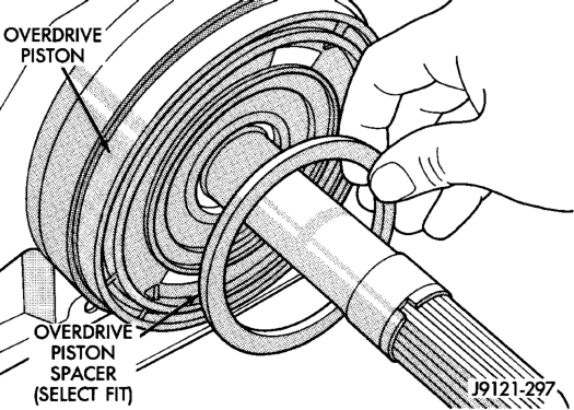
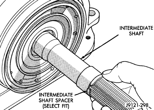
(2) Remove intermediate shaft spacer (Fig. 196). Retain spacer. It is a select fit part and may possibly be reused.
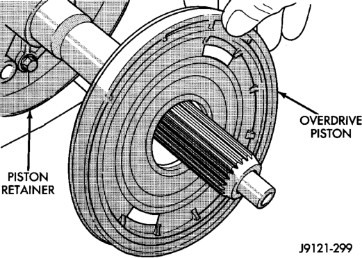
(3) Remove overdrive piston from retainer (Fig. 197).
OVERDRIVE CLUTCH PACK
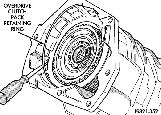
(1) Remove overdrive clutch pack wire retaining ring (Fig. 198).
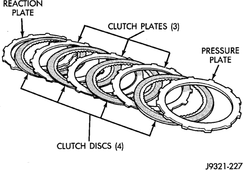
(2) Remove overdrive clutch pack (Fig. 199). (3) Note position of clutch pack components for assembly reference (Fig. 200).
Ring
Position
OVERDRIVE GEARTRAIN
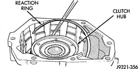
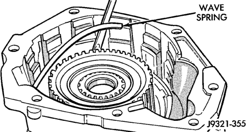
(1) Remove overdrive clutch wave spring (Fig. 201).
(2) Remove overdrive clutch reaction snap ring (Fig. 202). Note that snap ring is located in same groove as wave spring.
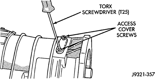
(3) Remove Torx head screws that attach access cover and gasket to overdrive case (Fig. 203).
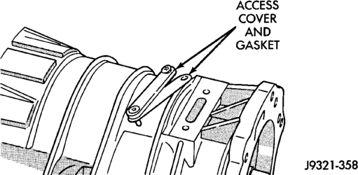
(4) Remove access cover and gasket (Fig. 204).
Installation

Installation
(5)
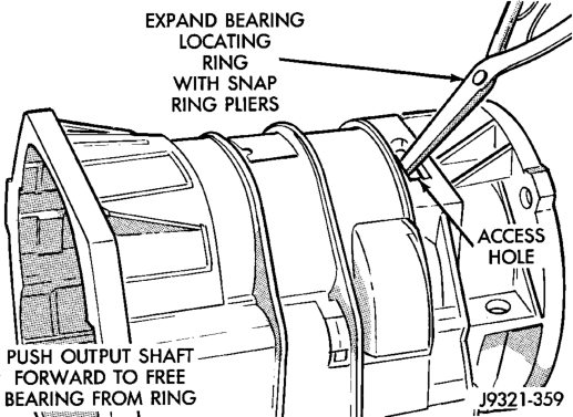
Expand output shaft bearing snap ring with

(Fig. 205).
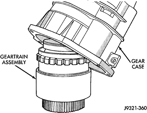
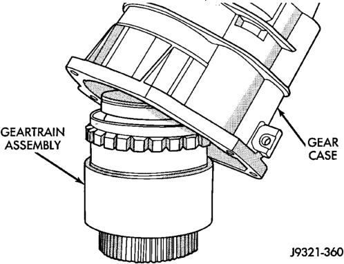
(6) Lift gear case up and off geartrain assembly (Fig. 206).
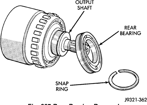
(7) Remove snap ring that retains rear bearing on output shaft.
Remove rear bearing from output shaft (Fig. 207).
(8)
DIRECT CLUTCH, HUB AND SPRING
RELEASE CLUTCH SPRING TENSION SLOWLY AND
COMPLETELY TO AVOID PERSONAL INJURY.
(1) Mount geartrain assembly in shop press (Fig. 208).
(2)
Position Compressor Tool 6227-1 on clutch hub

(3) Apply press pressure slowly. Compress hub and spring far enough to expose clutch hub retaining ring and relieve spring pressure on clutch pack snap ring (Fig. 208).
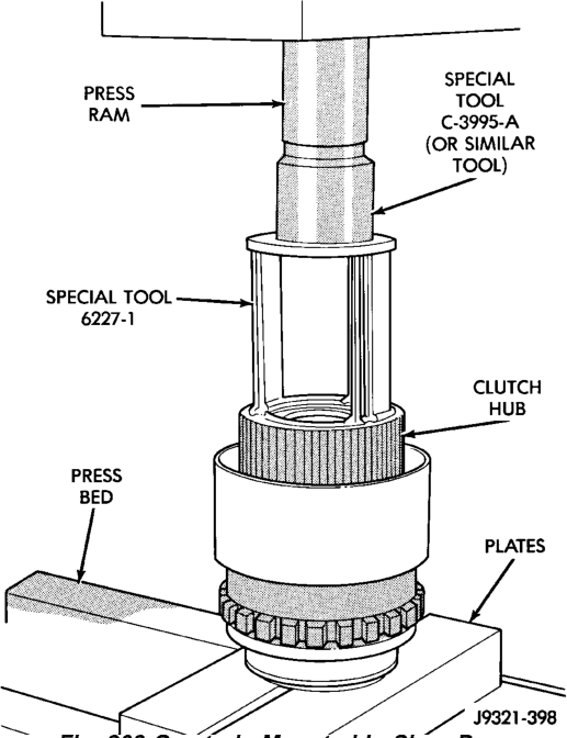
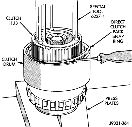
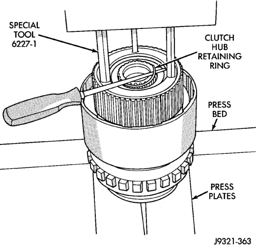
(4) Remove direct clutch pack snap ring (Fig. 209). (5) Remove direct clutch hub retaining ring (Fig. 210).
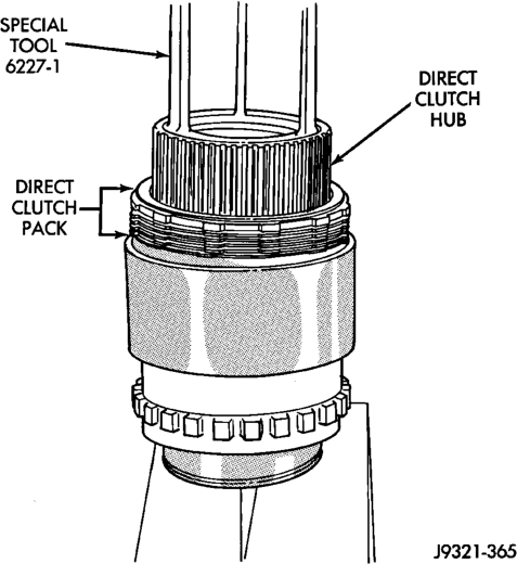
(6) Release press load slowly and completely (Fig. 211).
(7) Remove Special Tool 6227-1. Then remove clutch pack from hub (Fig. 211).
Geartrain
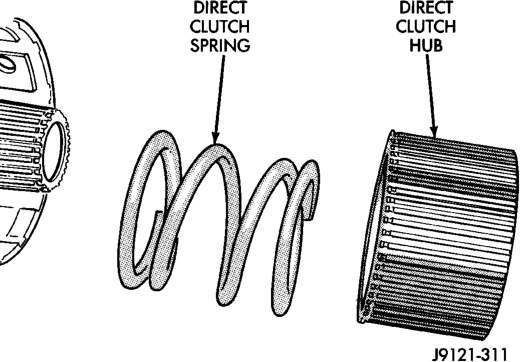
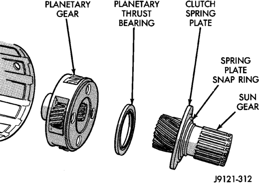
(1) Remove direct clutch hub and spring (Fig. 212). (2) Remove sun gear and spring plate. Then remove planetary thrust bearing and planetary gear (Fig. 213).
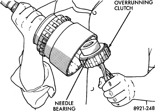
(3)
Remove overrunning clutch assembly with

remove clutch with counterclockwise, twisting motion.
(4) Remove thrust bearing from overrunning clutch hub.
(5) Remove overrunning clutch from hub. (6)
Mark position of annulus gear and direct clutch sinall center punch or seriber to make alignment marks
Planetary Gear
Installation
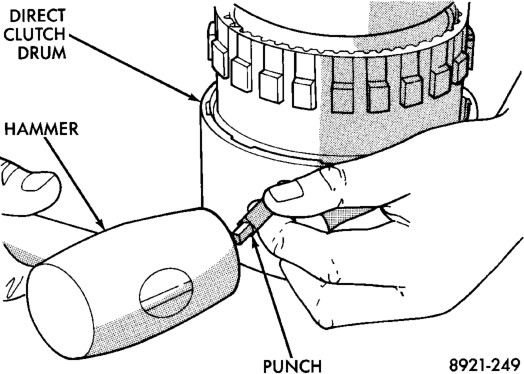
Gear For Assembly Alignment
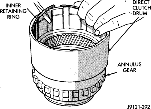
(7) Remove direct clutch drum rear retaining ring (Fig. 216).
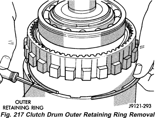
(8) Remove direct clutch drum outer retaining ring (Fig. 217).
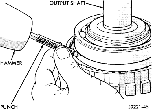
(9) Mark annulus gear and output shaft for assembly alignment reference (Fig. 218). Use punch or scriber to mark gear and shaft.
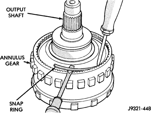
(10) Remove snap ring that secures annulus gear on output shaft (Fig. 219). Use two screwdrivers to unseat and work snap ring out of groove as shown.
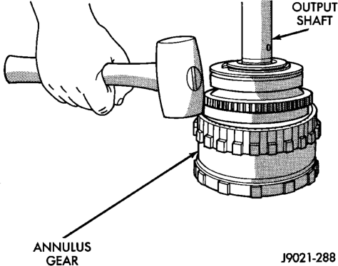
(11) Remove annulus gear from output shaft (Fig. 220). Use rawhide or plastic mallet to tap gear off shaft.
GEAR CASE AND PARK LOCK
(1) Remove locating ring from gear case. (2) Remove park pawl shaft retaining bolt and remove shaft, pawl and spring.
(3) Remove reaction plug snap ring and remove reaction plug.
(4) Remove output shaft seal.
For Assembly Alignment
ASSEMBLY
GEARTRAIN AND DIRECT CLUTCH
(1) Soak direct clutch and overdrive clutch discs in Mopart ATF Plus 3, type 7176, transmission fluid. Allow discs to soak for 10-20 minutes.
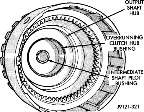
(2) Install new pilot bushing and clutch hub bushing in output shaft if necessary (Fig. 221). Lubricate bushings with petroleum jelly, or transmission fluid.
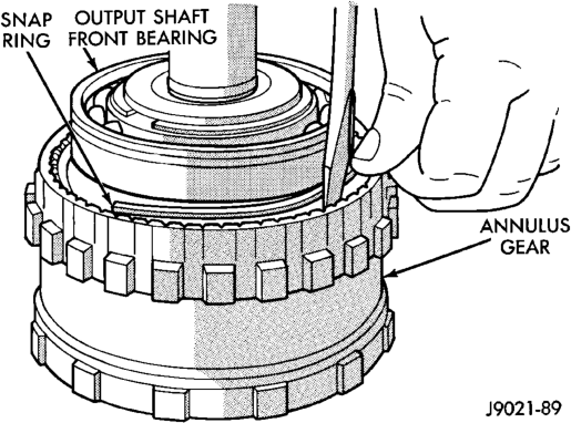
(3) Install annulus gear on output shaft, if removed. Then install annulus gear retaining snap ring (Fig. 222).
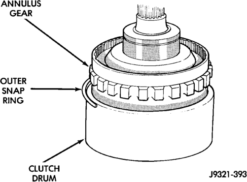
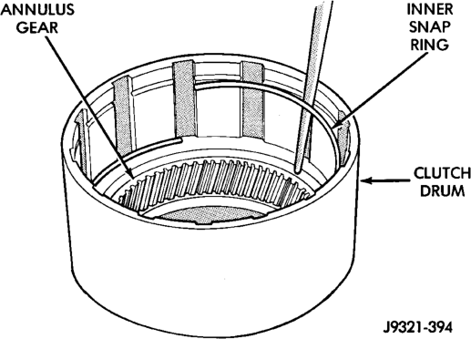
(4) Align and install clutch drum on annulus gear (Fig. 223). Be sure drum is engaged in annulus gear lugs.
(5) Install clutch drum outer retaining ring (Fig. 223).
(6) Slide clutch drum forward and install inner retaining ring (Fig. 224).
Installation
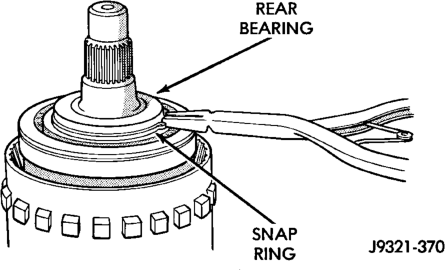
(7) Install rear bearing and snap ring on output shaft (Fig. 225). Be sure locating ring groove in bearing is toward rear.
Installation
(8) Install overrunning clutch on hub (Fig. 226). Note that clutch only fits one way. Shoulder on clutch should seat in small recess at edge of hub.
(9) Install thrust bearing on overrunning clutch hub. Use generous amount of petroleum jelly to hold bearing in place for installation. Bearing fits one way only. Be sure bearing is seated squarely against hub. Reinstall bearing if it does not seat squarely.
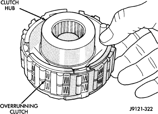
(10) Install overrunning clutch in output shaft (Fig. 227). Insert snap ring pliers in hub splines. Expand pliers to grip hub. Then install assembly with counterclockwise, twisting motion.
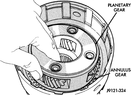
(11) Install planetary gear in annulus gear (Fig. 228). Be sure planetary pinions are fully seated in annulus gear before proceeding. (12) Coat planetary thrust bearing and bearing contact surface of spring plate with generous amount of petroleum jelly. This will help hold bearing in place during installation.
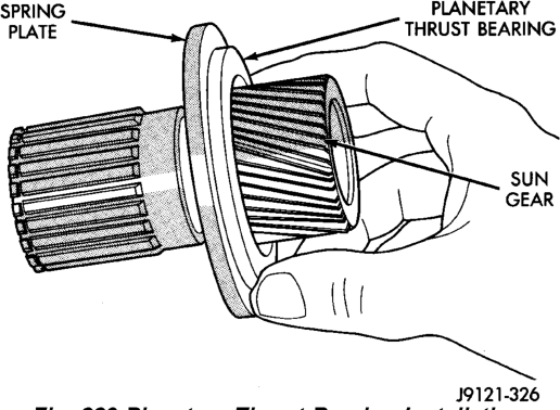
(13) Install planetary thrust bearing on sun gear (Fig. 229). Slide bearing onto gear and seat it against spring plate as shown. Bearing fits one way only. If it does not seat squarely against spring plate, remove and reposition bearing.
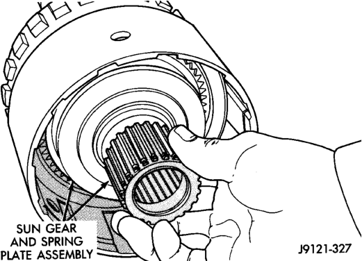
(14) Install assembled sun gear, spring plate and thrust bearing (Fig. 230). Be sure sun gear and thrust bearing are fully seated before proceeding.
(15) Mount assembled output shaft, annulus gear, and clutch drum in shop press. Direct clutch spring, hub and clutch pack are easier to install with assembly mounted in press.
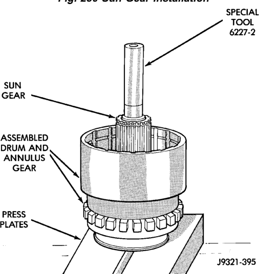
(16) Align splines in hubs of planetary gear and overrunning clutch with Alignment tool 6227-2 (Fig. 231). Insert tool through sun gear and into splines of both hubs. Be sure alignment tool is fully seated before proceeding.
(17) Install direct clutch spring (Fig. 232). Be sure spring is properly seated on spring plate.
(18) Assemble and install direct clutch pack on hub as follows:
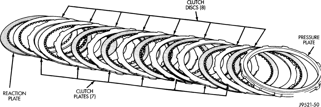
(a) Assemble clutch pack components (Fig. 233). (b) Install direct clutch reaction plate on clutch hub first. Note that one side of reaction plate is counterbored. Be sure this side faces rearward. Splines at rear of hub are raised
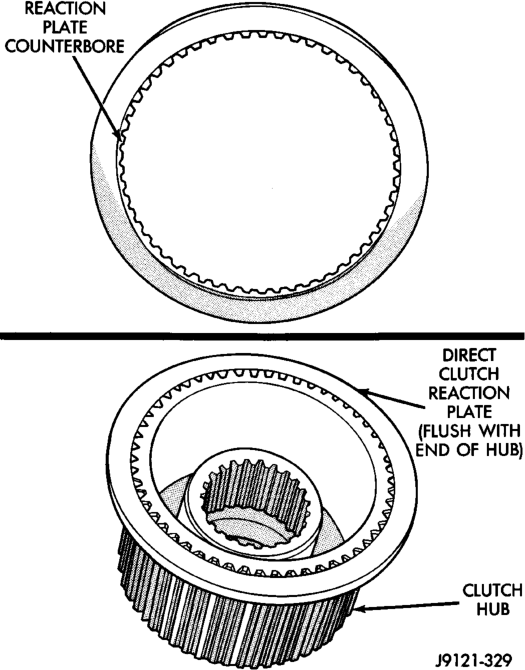
slightly. Counterbore in plate fits over raised splines. Plate should be flush with this end of hub (Fig. 234).
(c) Install first clutch disc followed by a steel plate until all discs and plates have been installed.
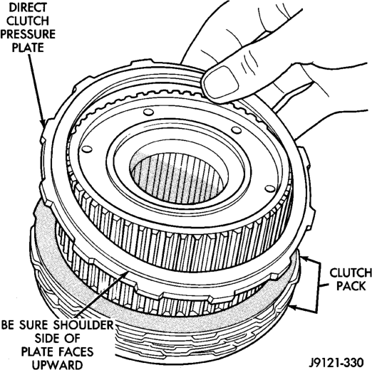
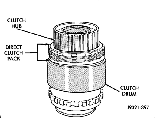
(d) Install pressure plate. This is last clutch pack item to be installed. Be sure plate is installed with shoulder side facing upward (Fig. 235). (19) Install clutch hub and clutch pack on direct clutch spring (Fig. 236). Be sure hub is started on sun gear splines before proceeding.
Fig. 233 46RE Direct Clutch Pack Components
Plate
Plate
Installation
WARNING: THE NEXT STEP IN GEARTRAIN ASSEMBLY INVOLVES COMPRESSING THE DIRECT CLUTCH HUB AND SPRING. IT IS EXTREMELY IMPORTANT THAT PROPER EQUIPMENT BE USED TO COMPRESS THE SPRING AS SPRING FORCE IS APPROXIMATELY 830 POUNDS. USE COMPRES- SOR TOOL C-6227-1 AND A HYDRAULIC-TYPE SHOP PRESS WITH A MINIMUM RAM TRAVEL OF 6 INCHES. THE PRESS MUST ALSO HAVE A BED THAT CAN BE ADJUSTED UP OR DOWN AS REQUIRED. RELEASE CLUTCH SPRING TENSION SLOWLY AND COMPLETELY TO AVOID PERSONAL INJURY.
(20) Position Compressor Tool 6227-1 on clutch hub.
(21) Compress clutch hub and spring just enough to place tension on hub and hold it in place.
(22) Slowly compress clutch hub and spring. Compress spring and hub only enough to expose ring grooves for clutch pack snap ring and clutch hub retaining ring.
(23) Realign clutch pack on hub and seat clutch discs and plates in clutch drum.
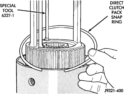
(24) Install direct clutch pack snap ring (Fig. 237). Be very sure snap ring is fully seated in clutch drum ring groove.
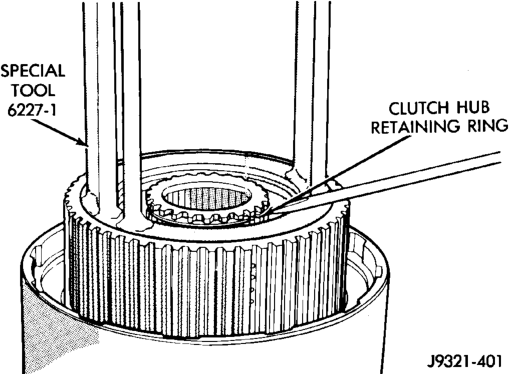
(25) Install clutch hub retaining ring (Fig. 238). Be very sure retaining ring is fully seated in sun gear ring groove.
(26) Slowly release press ram, remove compressor tools and remove geartrain assembly.
GEAR CASE
(1) Position park pawl and spring in case and install park pawl shaft. Verify that end of spring with 90° bend is hooked to pawl and straight end of spring is seated against case.
(2) Install pawl shaft retaining bolt. Tighten bolt to 27 N·m (20 ft. lbs.) torque.
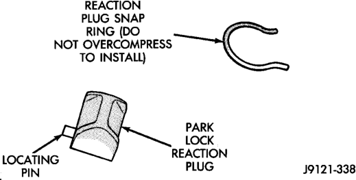
(3) Install park lock reaction plug. Note that plug has locating pin at rear (Fig. 239). Be sure pin is seated in hole in case before installing snap ring.
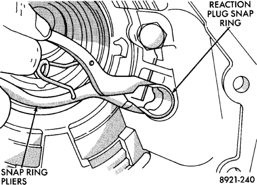
(4) Install reaction plug snap-ring (Fig. 240). Compress snap ring only enough for installation; do not distort it.
(5) Install new seal in gear case. Use Handle C-4171 and Installer C-3995-A to seat seal in case.
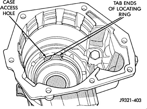
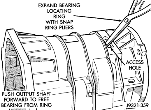
(6) Verify that tab ends of rear bearing locating ring extend into access hole in gear case (Fig. 241).
(7) Support geartrain on Tool 6227-1 (Fig. 242). Be sure tool is securely seated in clutch hub.
(8) Install overdrive gear case on geartrain (Fig. 242).
(9) Expand front bearing locating ring with snap ring pliers (Fig. 243). Then slide case downward until locating ring locks in bearing groove and release snap ring.
(10) Install locating ring access cover and gasket in overdrive unit case (Fig. 244).
Position
Installation
OVERDRIVE CLUTCH
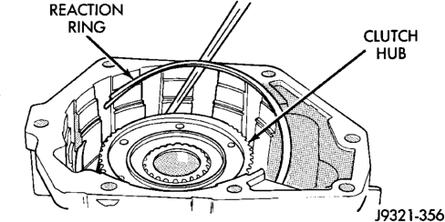
(1) Install overdrive clutch reaction ring first. Reaction ring is flat with notched ends (Fig. 245).
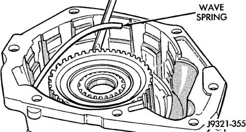
(2) Install wave spring on top of reaction ring (Fig. 246). Reaction ring and wave ring both fit in same ring groove. Use screwdriver to seat each ring securely in groove. Also ensure that the ends of the two rings are offset from each other.
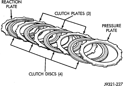
(3) Assemble overdrive clutch pack (Fig. 247).
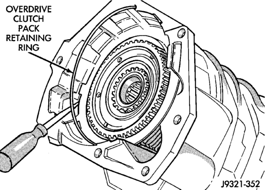
(4) Install overdrive clutch reaction plate first. (5) Install first clutch disc followed by first clutch plate. Then install remaining clutch discs and plates in same order. (6) Install clutch pack pressure plate. (7) Install clutch pack wire-type retaining ring (Fig. 248).
Installation
INTERMEDIATE SHAFT SPACER SELECTION
(1) Place overdrive unit in vertical position. Mount it on blocks, or in workbench with appropriate size mounting hole cut into it. Be sure unit is facing upward for access to direct clutch hub. Also be sure output shaft is not loaded and internal components are moved rearward for accurate measurement.
(2) Determine correct thickness intermediate shaft spacer as follows:
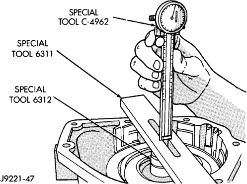
(a) Insert Special Tool 6312 through sun gear, planetary gear and into pilot bushing in output shaft. Be sure tool bottoms against planetary shoulder.
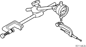
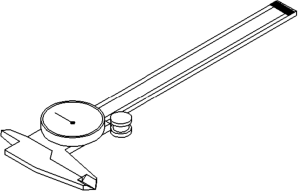
(b) Position Gauge Tool 6311 across face of overdrive case (Fig. 249). Then position Dial Caliper C-4962 over gauge tool.
(c) Extend sliding scale of dial caliper downward through gauge tool slot until scale contacts end of Gauge Alignment Tool 6312. Lock scale in place. Remove dial caliper tool and note distance measured (Fig. 249).
(d)
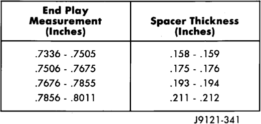
Select proper thickness end play spacer from spacer chart based on distance measured (Fig. 250).
(e) Remove Gauge Alignment Tool 6312.
Selection
OD THRUST PLATE SELECTION
(1) Place overdrive unit in vertical position. Mount it on blocks, or in workbench with appropriate size mounting hole cut into it. Be sure unit is facing upward for access to direct clutch hub. Also be sure output shaft is not loaded and internal components are moved rearward for accurate measurement.
(2) Determine correct thickness overdrive piston thrust plate as follows:
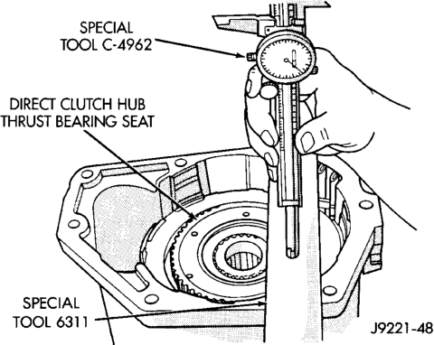
(a) Position Gauge Tool 6311 across face of overdrive case. Then position Dial Caliper C-4962 over gauge tool (Fig. 251).
(b) Measure distance to clutch hub thrust bearing seat at four points 90° apart. Then average measurements by adding them and dividing by 4.
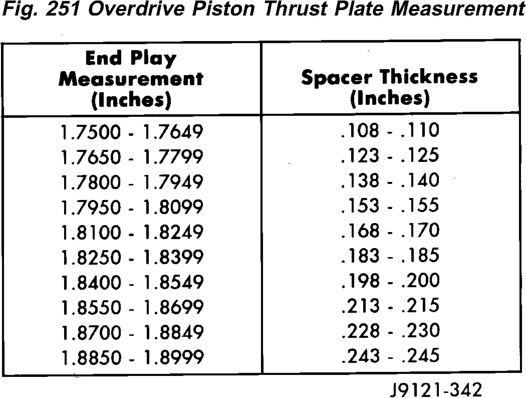
(c) Select and install required thrust plate from information in thrust plate chart (Fig. 252). (3)
Leave Alignment Tool 6227-2 in place. Tool will keep planetary and clutch hub splines in alignment until overdrive unit is ready for installation on transmission.
(4) Transmission speed sensor can be installed at this time if desired. However, it is recommended that sensor not be installed until after overdrive unit is secured to transmission.
OVERDRIVE PISTON
(1) Install new seals on overdrive piston. (2)
Stand transmission case upright on bellhousing.
(3) Position Guide Ring 8114-1 on outer edge of overdrive piston retainer.
(4) Position Seal Guide 8114-3 on inner edge of overdrive piston retainer.
(5) Install overdrive piston in overdrive piston retainer by:
(a) Aligning locating lugs on overdrive piston to the two mating holes in retainer.
(b) Lubricate overdrive piston seals with Mopart Door Ease, or equivalent.
(c) Install piston over Seal Guide 8114–3 and inside Guide Ring 8114–1. (d)
Push overdrive piston into position in retainer.
(e) Verify that the locating lugs entered the lug bores in the retainer. (6) Install intermediate shaft spacer on intermediate shaft.
(7) Install overdrive piston thrust plate on overdrive piston.
(8) Install overdrive piston thrust bearing on overdrive piston.
(9) Install transmission speed sensor and O-ring seal in overdrive case (Fig. 193).
CLEANING AND INSPECTION
VALVE Body
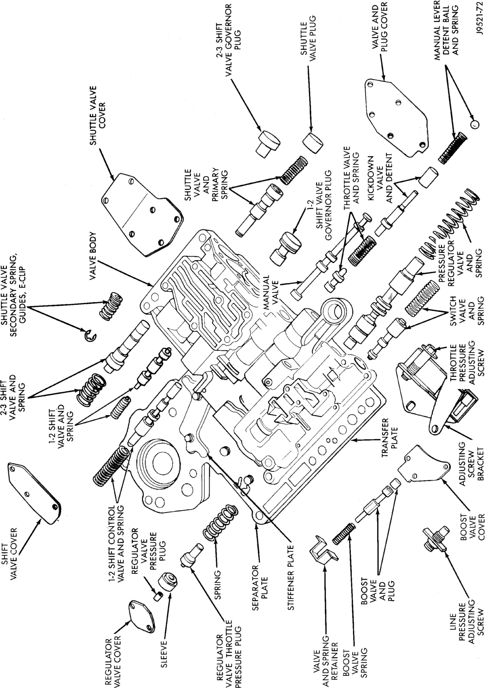
Clean the valve housings, valves, plugs, springs, and separator plates with a standard parts cleaning solution only. Do not use gasoline, kerosene, or any type of caustic solution.
Do not immerse any of the electrical components in cleaning solution. Clean the governor solenoid and sensor and the dual solenoid and harness assembly by wiping them off with dry shop towels only.
Dry all except the electrical parts with compressed air. Make sure all passages are clean and free from obstructions. Do not use rags or shop towels to dry or wipe off valve body components. Lint from these materials can stick to valve body parts, interfere with valve operation, and clog filters and fluid passages.
Wipe the governor pressure sensor and solenoid valve with dry, lint free shop towels only. The O-rings on the sensor and solenoid valve are the only serviceable components. Be sure the vent ports in the solenoid valve are open and not blocked by dirt or debris. Replace the valve and/or sensor only when DRB scan tool diagnosis indicates this is necessary. Or, if either part has sustained physical damage (dented, deformed, broken, etc.).
CAUTION: Do not turn the small screw at the end of the solenoid valve for any reason. Turning the screw in either direction will ruin solenoid calibration and result in solenoid failure. In addition, the filter on the solenoid valve is NOT serviceable. Do not try to remove the filter as this will damage the valve hous-
Inspect the throttle and manual valve levers and shafts (Fig. 253). Do not attempt to straighten a bent shaft or correct a loose lever. Replace these components if worn, bent, loose or damaged in any way.
Inspect all of the valve body mating surfaces for

Minor distortion of a valve body mating surface may be corrected by smoothing the surface with a sheet of crocus cloth. Position the crocus cloth on a surface plate, sheet of plate glass or equally flat surface. If distortion is severe or any surfaces are heavily scored, the valve body will have to be replaced.
CAUTION: Many of the valves and plugs, such as the throttle valve, shuttle valve plug, 1-2 shift valve and 1-2 governor plug, are made of coated aluminum. Aluminum components are identified by the dark color of the special coating applied to the surface (or by testing with a magnet). Do not sand aluminum valves or plugs under any circumstances. This practice could damage the special coating causing the valves/plugs to stick and bind.
Inspect the valves and plugs for scratches, burrs, nicks, or scores. Minor surface scratches on steel valves mould off the edges of the valve or plug lands
Maintaining sharpness of these edges is vitally important. The edges prevent foreign matter from lodging between the valves and plugs and the bore.
Inspect all the valve and plug bores in the valve body.
Use a penlight to view the bore interiors. Replace the valve body if any bores are distorted or scored. Inspect all of the valve body springs. The springs must be free of distortion, warpage or broken coils.
Check the two separator plates for distortion or damage of any kind. Inspect the upper housing, lower housing, 3-4 accumulator housing, and transfer plate carefully. Be sure all fluid passages are clean and clear. Check condition of the upper housing and transfer plate check balls as well. The check balls and ball seats must not be worn or damaged.
Trial fit each valve and plug in its bore to check freedom of operation. When clean and dry, the valves and plugs should drop freely into the bores.
Valve body bores do not change dimensionally with use. If the valve body functioned correctly when new, it will continue to operate properly after cleaning and inspection. It should not be necessary to replace a valve body assembly unless it is damaged in handling.
The only serviceable valve body components are listed below. The remaining valve body components are serviced only as part of a complete valve body assembly. Serviceable parts are:
• dual solenoid and harness assembly • solenoid gasket • solenoid case connector O-rings and shoulder bolt
• switch valve and spring • pressure adjusting screw and bracket assembly • throttle lever • manual lever and shaft seal • throttle lever shaft seal, washer, and E-clip • fluid filter and screws • detent ball and spring • valve body screws • governor pressure solenoid • governor pressure sensor and retaining clip • park lock rod and E-clip

TRANSMISSION
GENERAL INFORMATION
Inspect the transmission bushings during overhaul. Bushing condition is important as worn, scored bushings contribute to low pressures, clutch slip and accelerated wear of other components. However, do not replace bushings as a matter of course. Replace bushings only when they are actually worn, or scored.
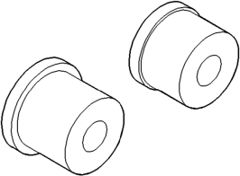
Use recommended tools to replace bushings. The tools are sized and designed to remove, install, and seat bushings correctly. The bushing replacement tools are included in Bushing Tool Set C-3887-B.
Pre-sized service bushings are available for replacement purposes. Only the sun gear bushings are not serviced. Low cost of the sun gear assembly makes it easier to simply replace the gear and bushings as an assembly. Heli-Coil inserts can be used to repair damaged, stripped or worn threads in aluminum parts. These inserts are available from most automotive parts suppliers. Stainless steel inserts are recommended.
The use of crocus cloth is permissible where necessary, providing it is used carefully. When used on shafts, or valves, use extreme care to avoid rounding off sharp edges. Sharp edges are vital as they prevent foreign matter from getting between the valve and valve bore.
Do not reuse oil seals, gaskets, seal rings, or O-rings during overhaul. Replace these parts as a matter of course. Also do not reuse snap rings or E-clips that are bent or distorted. Replace these parts as well.
Lubricate transmission parts with Mopart ATF Plus, Type 7176, transmission fluid during overhaul and assembly. Use petroleum jelly, Mopart Door Ease, or Ru-Glyde to prelubricate seals, O-rings, and thrust washers. Petroleum jelly can also be used to hold parts in place during reassembly.
TRANSMISSION CASE CLEANING AND
INSPECTION
Clean the case in a solvent tank. Flush the case bores and fluid passages thoroughly with solvent. Dry the case and all fluid passages with compressed air. Be sure all solvent is removed from the case and that all fluid passages are clear.
NOTE: Do not use shop towels or rags to dry the case (or any other transmission component) unless they are made from lint-free materials. Lint will stick to case surfaces and transmission components and circulate throughout the transmission after assembly. A sufficient quantity of lint can block fluid passages and interfere with valve body operation.
Inspect the case for cracks, porous spots, worn bores, or damaged threads. Damaged threads can be repaired with Helicoil thread inserts. However, the case will have to be replaced if it exhibits any type of damage or wear.
Lubricate the front band adjusting screw threads with petroleum jelly and thread the screw part-way into the case. Be sure the screw turns freely.
OVERRUNNING CLUTCH/LOW-REVERSE DRUM/OVERDRIVE PISTON RETAINER
Clean the overrunning clutch assembly, clutch cam, low-reverse drum, and overdrive piston retainer in solvent. Dry them with compressed air after cleaning. Inspect condition of each clutch part after cleaning. Replace the overrunning clutch roller and spring assembly if any rollers or springs are worn or damaged, or if the roller cage is distorted, or damaged. Replace the cam if worn, cracked or damaged.
Replace the low-reverse drum if the clutch race, roller surface or inside diameter is scored, worn or damaged. Do not remove the clutch race from the low-reverse drum under any circumstances. Replace the drum and race as an assembly if either component is damaged.
Examine the overdrive piston retainer carefully for wear, cracks, scoring or other damage. Be sure the retainer hub is a snug fit in the case and drum. Replace the retainer if worn or damaged.
ACCUMULATOR
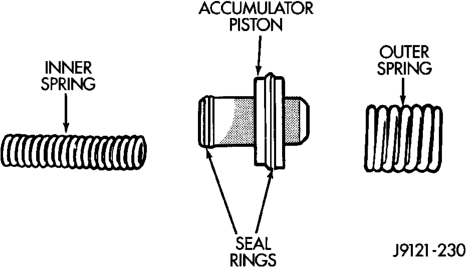
Inspect the accumulator piston and seal rings (Fig. 254). Replace the seal rings if worn or cut. Replace the piston if chipped or cracked.
Check condition of the accumulator inner and outer springs (Fig. 254). Replace the springs if the coils are cracked, distorted or collapsed.
FRONT SERVO
Clean the servo piston components with solvent and dry them with compressed air. Wipe the band clean with lint free shop towels.
Replace the front band if distorted, lining is burned, flaking off, or worn to the point where the grooves in the lining material are no longer visible.
Inspect the servo components. Replace the springs if collapsed, distorted or broken. Replace the guide, rod and piston if cracked, bent, or worn. Discard the servo snap ring if distorted or warped.
Check the servo piston bore for wear. If the bore is severely scored, or damaged, it will be necessary to replace the case.
Replace any servo component if doubt exists about condition. Do not reuse suspect parts.
REAR SERVO
Remove and discard the servo piston seal ring (Fig. 255). Then clean the servo components with solvent and dry with compressed air. Replace either spring if collapsed, distorted or broken. Replace the plug and piston if cracked, bent, or worn. Discard the servo snap rings and use a new ones at assembly.
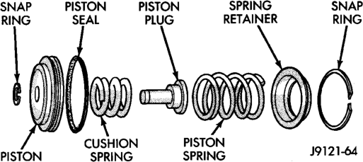
OIL PUMP AND REACTION SHAFT SUPPORT
Clean pump and support components with solvent and dry them with compressed air.
Check condition of the seal rings and thrust washer on the reaction shaft support. The seal rings do not need to be replaced unless cracked, broken, or severely worn.
Inspect the pump and support components. Replace the pump or support if the seal ring grooves or machined surfaces are worn, scored, pitted, or damaged. Replace the pump gears if pitted, worn chipped, or damaged.
Check the pump vent. The vent must be secure. Replace the pump body if the vent is cracked, broken, or loose.
Inspect the pump bushing. Then check the reaction shaft support bushing. Replace either bushing only if heavily worn, scored or damaged. It is not necessary to replace the bushings unless they are actually damaged.
(1) Install the gears in the pump body and measure pump component clearances as follows:
(a) Clearance between outer gear and reaction shaft housing should be 0.010 to 0.063 mm (0.0004 to 0.0025 in.). Clearance between inner gear and reaction shaft housing should be 0.010 to 0.063 mm (0.0004 to 0.0025 in.). Both clearances can be measured at the same time by:
(I) Installing the pump gears in the pump housing.
(II) Position an appropriate piece of Plastigagey across both gears.
(III) Align the plastigage to a flat area on the reaction shaft housing.
(IV) Install the reaction shaft to the pump housing.
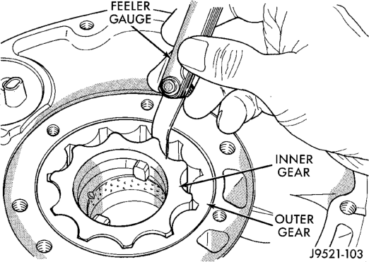
(V) Separate the reaction shaft housing from the pump housing and measure the Plastigagey following the instructions supplied with it. (b) Clearance between inner gear tooth and outer gear should be 0.08 to 0.19 mm (0.0035 to 0.0075 in.). Measure clearance with an appropriate feeler gauge (Fig. 256).
(c) Clearance between outer gear and pump housing should also be 0.010 to 0.19 mm (0.0035 to 0.0075 in.). Measure clearance with an appropriate feeler gauge.
FRONT CLUTCH
Clean and inspect the front clutch components. Replace the clutch discs if warped, worn, scored, burned or charred, the lugs are damaged, or if the facing is flaking off. Replace the steel plates and reaction plate if heavily scored, warped, or broken. Be sure the driving lugs on the discs and plate are also in good condition. The lugs must not be bent, cracked or damaged in any way.
Replace the piston springs and spring retainer if either are distorted, warped or broken.
Check the lug grooves in the clutch piston retainer. The steel plates should slide freely in the slots. Replace the piston retainer if the grooves are worn or damaged. Also check action of the check ball in the piston retainer. The ball must move freely and not stick.
Replace the retainer bushing if worn, scored, or there is any doubt about bushing condition.
Inspect the piston and retainer seal surfaces for nicks or scratches. Minor scratches can be removed with crocus cloth. However, replace the piston and/or retainer if the seal surfaces are seriously scored.
Check the clutch piston check ball. The ball should be securely in place. Replace the piston if the ball is missing, or seized in place.
REAR CLUTCH
Clean the clutch components with solvent and dry them with compressed air.
Check condition of the input shaft seal rings. It is not necessary to remove or replace rings unless they are broken, cracked, or no longer securely hooked together.
Inspect the input shaft splines and machined surfaces. Very minor nicks or scratches can be smoothed off with crocus cloth. replace the shaft if the splines are damaged, or any of the machined surfaces are severely scored.
Replace the clutch discs if warped, worn, scored, burned/charred, the lugs are damaged, or if the facing is flaking off. Replace the steel plates and the pressure plate if heavily scored, warped, or broken. Be sure the driving lugs on the discs and plates are also in good condition. The lugs must not be bent, cracked or damaged in any way.
Replace the piston spring and wave spring if either part is distorted, warped or broken.
Check the lug grooves in the clutch retainer. The steel plates should slide freely in the slots. Replace the retainer if the grooves are worn or damaged. Also check action of the retainer check ball. The ball must move freely and not stick.
Inspect the piston and retainer seal surfaces for nicks or scratches. Minor scratches can be removed with crocus cloth. However, replace the piston and/or retainer if the seal surfaces are seriously damaged.
Check thrust washer condition. Washer thickness should be 1.55 to 1.60 mm (0.061 to 0.063 in.). Replace the washer if worn or damaged.
Check condition of the two seal rings on the input shaft and the single seal ring on the piston retainer hub. Replace the seal rings only if severely worn, cracked, or cannot be hooked together.
PLANETARY GEARTRAIN/OUTPUT SHAFT
Clean the intermediate shaft and planetary components in solvent and dry them with compressed air.
Inspect the planetary gear sets and annulus gears. The planetary pinions, shafts, washers, and retaining pins are serviceable. However, if a pinion carrier is damaged, the entire planetary gear set must be replaced as an assembly.
Replace the annulus gears if the teeth are chipped, broken, or worn, or the gear is cracked. Replace the planetary thrust plates and the tabbed thrust washers if cracked, scored or worn.
Inspect the machined surfaces of the intermediate shaft. Be sure the oil passages are open and clear. Replace the shaft if scored, pitted, or damaged.
Inspect the sun gear and driving shell. If either component is worn or damaged, remove the sun gear rear retaining ring and separate the sun gear and thrust plate from the driving shell. Then replace the necessary component.
Replace the sun gear as an assembly if the gear teeth are chipped or worn. Also replace the gear as an assembly if the bushings are scored or worn. The sun gear bushings are not serviceable. Replace the thrust plate if worn, or severely scored. Replace the driving shell if distorted, cracked, or damaged in any way.
Replace all snap rings during geartrain assembly. Reusing snap rings is not recommended.
OVERDRIVE UNIT
Clean the geartrain and case components with solvent. Dry all parts except the bearings with compressed air. Allow bearings to air dry.
Do not use shop towels for wiping parts dry unless the towels are made from a lint-free material. A sufficient quantity of lint (from shop towels, cloths, rags, etc.) could plug the transmission filter and fluid passages.
Discard the old case gasket and seals. Do not attempt to salvage these parts. They are not reusable. Replace any of the overdrive unit snap rings if distorted or damaged.
Minor nicks or scratches on components can be smoothed with crocus cloth. However, do not attempt to reduce severe scoring on any components with abrasive materials. Replace severely scored components; do not try to salvage them.
Check condition of the park lock components and the overdrive case.
Replace the case if cracked, scored, or damaged. Replace the park lock pawl, plug, or spring if worn or damaged. Be sure the bullet at the end of the park lock rod is in good condition. Replace the rod if the bullet is worn or the rod itself is bent or distorted. Do not attempt to straighten the rod.
Check the bushings in the overdrive case. Replace the bushings if severely scored or worn. Also replace the case seal if loose, distorted, or damaged.
Examine the overdrive and direct clutch discs and plates. Replace the discs if the facing is worn, severely scored, or burned and flaking off. Replace the clutch plates if worn, heavily scored, or cracked. Check the lugs on the clutch plates for wear. The plates should slide freely in the drum. Replace the plates or drum if binding occurs.
Check condition of the annulus gear, direct clutch hub, clutch drum and clutch spring. Replace the gear, hub and drum if worn or damaged. Replace the spring if collapsed, distorted, or cracked.
Be sure the splines and lugs on the gear, drum and hub are in good condition. The clutch plates and discs should slide freely in these components.
Inspect the thrust bearings and spring plate. Replace the plate if worn or scored. Replace the bearings if rough, noisy, brinnelled, or worn. Inspect the planetary gear assembly and the sun gear and bushings. If either the sun gear or the bushings are damaged, replace the gear and bushings as an assembly. The gear and bushings are not serviced separately.
The planetary carrier and pinions must be in good condition. Also be sure the pinion pins are secure and in good condition. Replace the carrier if worn or damaged.
Inspect the overrunning clutch and race. The race surface should be smooth and free of scores. Replace the overrunning clutch assembly or the race if either assembly is worn or damaged in any way.
Inspect the output shaft and governor components. Replace the shaft pilot bushing and inner bushing if damaged. Replace either shaft bearing if rough or noisy. Replace the bearing snap rings if distorted or cracked.
Check the machined surfaces on the output shaft. These surfaces should clean and smooth. Very minor nicks or scratches can be smoothed with crocus cloth. Replace the shaft if worn, scored or damaged in any way.
Inspect the output shaft bushings. The small bushing is the intermediate shaft pilot bushing. The large bushing is the overrunning clutch hub bushing. Replace either bushing if scored, pitted, cracked, or worn.
ADJUSTMENTS
BRAKE TRANSMISSION SHIFT INTERLOCK
The park interlock cable is part of the brake/shift lever interlock system. Correct cable adjustment is important to proper interlock operation. The gear shift and park lock cables must both be correctly adjusted in order to shift out of Park.
Park Interlock Cable Adjustment Procedure
(1) Shift into Park position.
(2) Turn ignition switch to Accessory position. Be sure ignition key cylinder is in Accessory position. Cable will not adjust correctly in any other position.
(3) Remove shift lever bezel and console screws. Raise bezel and console for access to park interlock cable.
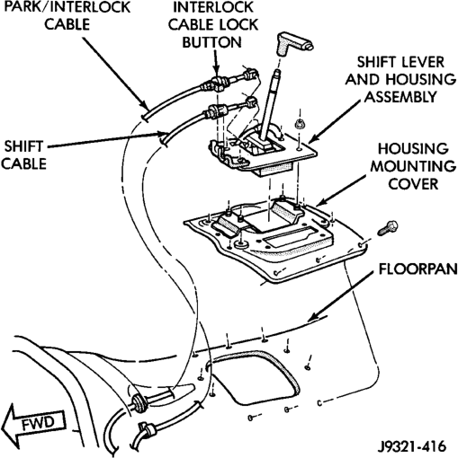
(4) Pull cable lock button up to release cable (Fig. 257).
(5) Pull cable forward. Then release cable and press lock button down until it snaps in place.
BTSI FUNCTION CHECK
(1) Verify removal of ignition key allowed in park position only.
(2) When the shift lever is in park, and the shift handle push-button is in the out position, the ignition key cylinder should rotate freely from off to lock. When the shifter is in any other position, the ignition key should not rotate from off to lock.
(3) Shifting out of park should be possible when the ignition key cylinder is in the off position.
(4) Shifting out of park should not be possible while applying 25 lb. max. handle push-button force, and ignition key cylinder is in the run or start positions, unless the foot brake pedal is depressed approximately 1/2 inch (12mm).
(5) Shifting out of park should not be possible when the ignition key cylinder is in the accessory or lock position.
(6) Shifting between any gears neutral or park may be done without depressing foot brake with ignition switch in run or start positions and vehicle stationary or in motion.
(7) The floorshifter lever and gate positions should be in alignment with all transmission detent positions.
(8) Engine starts must be possible with floorshift lever in park or neutral gate positions only. Engine starts must not be possible in any other gate positions other than park or neutral.
(9) With floorshift lever handle push-button not depressed and lever detent in:
• PARK POSITION- apply forward force on center of handle and remove pressure. Engine start must be possible.
• PARK POSITION- apply rearward force on center of handle and remove pressure. Engine start must be possible.
• NEUTRAL POSITION- engine start must be possible.
• NEUTRAL POSITION, ENGINE RUNNING AND BRAKES APPLIED- Apply forward force on center of shift handle. Transmission should not be able to shift into reverse detent.
TRANSMISSION THROTTLE VALVE CABLE ADJUSTMENT
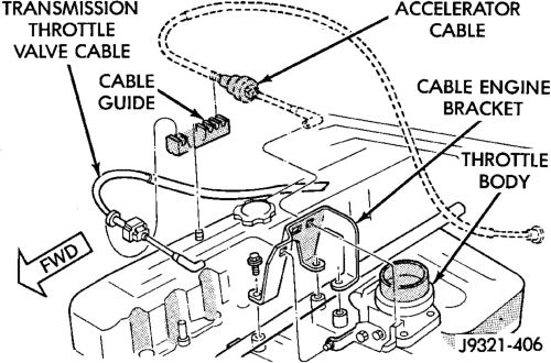
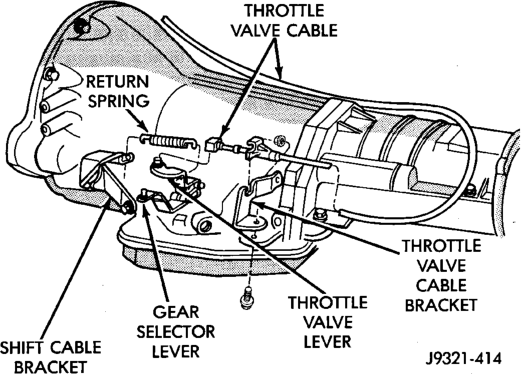
The transmission throttle valve is operated by a cam on the throttle lever. The throttle lever is operated by an adjustable cable (Fig. 258). The cable is attached to an arm mounted on the throttle lever shaft. A retaining clip at the engine-end of the cable is removed to provide for cable adjustment. The retaining clip is then installed back onto the throttle valve cable to lock in the adjustment.
A correctly adjusted throttle valve cable will cause the throttle lever on the transmission to move simultaneously with the throttle body lever from the idle position. Proper adjustment will allow simultaneous movement without causing the transmission throttle lever to either move ahead of, or lag behind the lever on the throttle body.
Checking Throttle Valve Cable Adjustment
(1) Turn ignition key to OFF position. (2) Remove air cleaner. (3) Verify that lever on throttle body is at curb idle position. Then verify that transmission throttle lever (Fig. 259) is also at idle (fully forward) position.
(4) Slide cable off attachment stud on throttle body lever.
(5) Compare position of cable end to attachment stud on throttle body lever:
• Cable end and attachment stud should be aligned (or centered on one another) to within 1 mm (0.039 in.) in either direction.
• If cable end and attachment stud are misaligned (off center), cable will have to be adjusted as described in Throttle Valve Cable Adjustment procedure.
(6) Reconnect cable end to attachment stud. Then with aid of a helper, observe movement of transmission throttle lever and lever on throttle body.
• If both levers move simultaneously from idle to half-throttle and back to idle position, adjustment is correct.
• If transmission throttle lever moves ahead of, or lags behind throttle body lever, cable adjustment will be necessary. Or, if throttle body lever prevents transmission lever from returning to closed position, cable adjustment will be necessary.
Throttle Valve Cable Adjustment Procedure
(1) Turn ignition switch to OFF position. (2) Remove air cleaner if necessary. (3) Disconnect cable end from attachment stud. Carefully slide cable off stud. Do not pry or pull cable off.
(4) Verify that transmission throttle lever is in fully closed position. Then be sure lever on throttle body is at curb idle position.
(5) Insert a small screwdriver under edge of retaining clip and remove retaining clip.
(6) Center cable end on attachment stud to within 1 mm (0.039 in.).
(7) Install retaining clip onto cable housing. (8) Check cable adjustment. Verify transmission throttle lever and lever on throttle body move simultaneously.
GEARSHIFT CABLE
Check adjustment by starting the engine in Park and Neutral. Adjustment is OK if the engine starts only in these positions. Adjustment is incorrect if the engine starts in one but not both positions. If the engine starts in any position other than Park or Neutral, or if the engine will not start at all, the park/ neutral position switch may be faulty.
Gearshift Adjustment Procedure
(1) Shift transmission into Park. (2) Raise vehicle. (3) Release cable adjuster clamp (at transmission end of cable) to unlock cable.
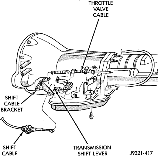
(4) Unsnap cable from cable mounting bracket on transmission (Fig. 260).
(5) Slide cable eyelet off transmission shift lever. (6) Verify transmission shift lever is in Park detent by moving lever fully rearward. Last rearward detent is Park position.
(7) Verify positive engagement of transmission park lock by attempting to rotate propeller shaft. Shaft will not rotate when park lock is engaged.
(8) Slide cable eyelt onto transmission shift lever. (9) Snap shift cable adjuster into mounting bracket on transmission.
(10) Lock shift cable by pressing cable adjuster clamp down until it snaps into place.
(11) Lower vehicle and check engine starting. Engine should start only in Park and Neutral.
FRONT BAND ADJUSTMENT
The front (kickdown) band adjusting screw is located on the left side of the transmission case above the manual valve and throttle valve levers.
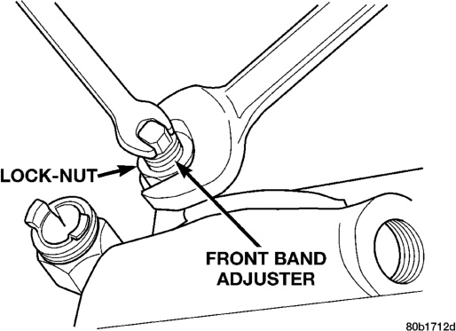
(1) Raise vehicle. (2) Loosen band adjusting screw locknut (Fig. 261). Then back locknut off 3-5 turns. Be sure adjusting screw turns freely in case. Apply lubricant to screw threads if necessary.
(3) Tighten band adjusting screw to 8 N·m (72 in. lbs.) torque with Inch Pound Torque Wrench C-3380-A, a 3-in. extension and 5/16 socket.
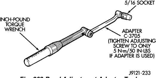
CAUTION: If Adapter C-3705 is needed to reach the adjusting screw (Fig. 262), tighten the screw to only 5 N·m (47-50 in. lbs.) torque.

(4)
Back off front band adjusting screw 2-7/8 turns.
(5) Hold adjuster screw in position and tighten locknut to 41 N·m (30 ft. lbs.) torque.
(6) Lower vehicle.
REAR BAND ADJUSTMENT
The transmission oil pan must be removed for access to the rear band adjusting screw.
(1) Raise vehicle. (2) Remove transmission oil pan and drain fluid. (3) Loosen band adjusting screw locknut 5-6 turns. Be sure adjusting screw turns freely in lever.
(4) Tighten adjusting screw to 8 N·m (72 in. lbs.) torque (Fig. 263).
(5) Back off adjusting screw 2 turns. (6) Hold adjusting screw in place and tighten locknut to 34 N·m (25 ft. lbs.) torque.
(7) Position new gasket on oil pan and install pan on transmission. Tighten pan bolts to 17 N·m (13 ft. lbs.) torque.
(8) Lower vehicle and refill transmission with Mopart ATF Plus, Type 7176 fluid.
VALVE Body
CONTROL PRESSURE ADJUSTMENTS
There are two control pressure adjustments on the valve body;
• Line Pressure • Throttle Pressure
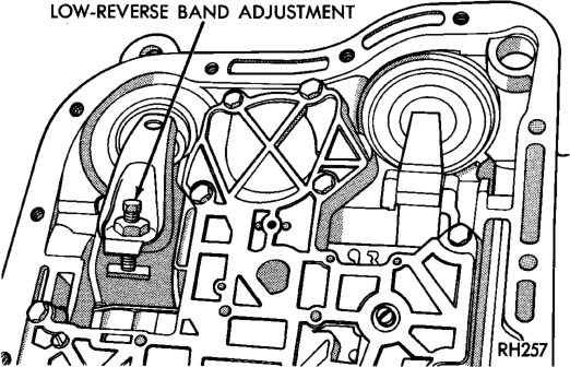
Line and throttle pressures are interdependent because each affects shift quality and timing. As a result, both adjustments must be performed properly and in the correct sequence. Adjust line pressure first and throttle pressure last.
LINE PRESSURE ADJUSTMENT
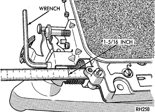
Measure distance from the valve body to the inner edge of the adjusting screw with an accurate steel scale (Fig. 264).
Distance should be 33.4 mm (1-5/16 in.). If adjustment is required, turn the adjusting screw in, or out, to obtain required distance setting.
NOTE: The 33.4 mm (1-5/16 in.) setting is an approximate setting. Manufacturing tolerances may make it necessary to vary from this dimension to obtain desired pressure.
One complete turn of the adjusting screw changes line pressure approximately 1-2/3 psi (9 kPa).
Turning the adjusting screw counterclockwise increases pressure while turning the screw clockwise decreases pressure.
THROTTLE PRESSURE ADJUSTMENT
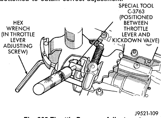
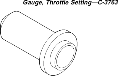
Insert Gauge Tool C-3763 between the throttle lever cam and the kickdown valve stem (Fig. 265).
Push the gauge tool inward to compress the kickdown valve against the spring and bottom the throttle valve.
Maintain pressure against kickdown valve spring. Turn throttle lever stop screw until the screw head touches throttle lever tang and the throttle lever cam touches gauge tool.
NOTE: The kickdown valve spring must be fully compressed and the kickdown valve completely bottomed to obtain correct adjustment.


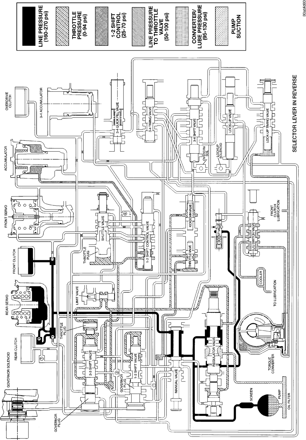

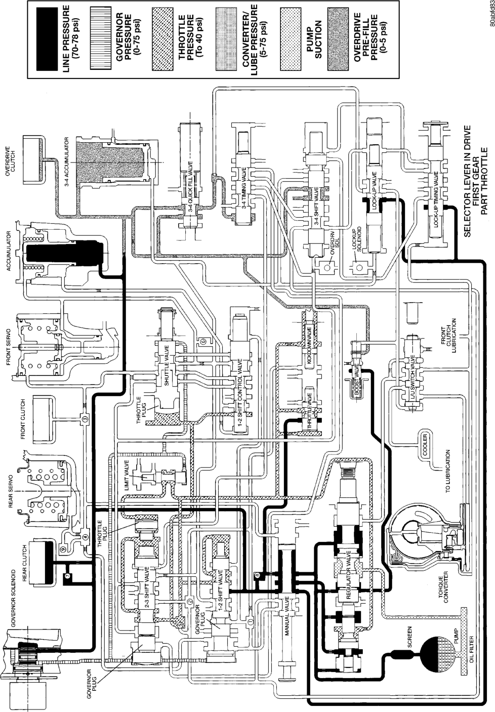

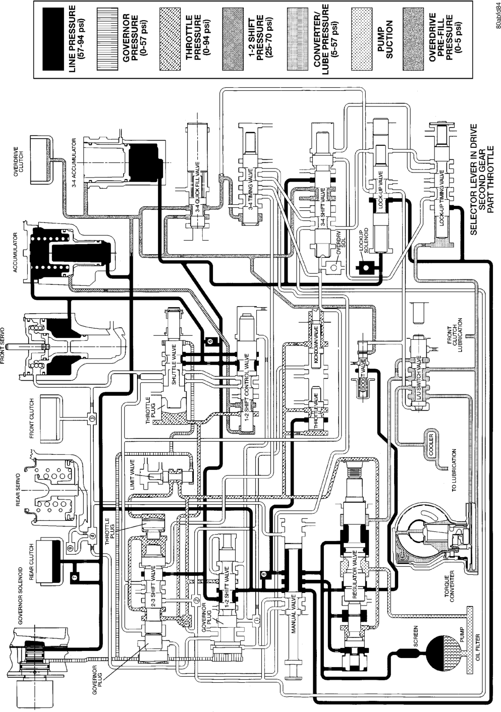

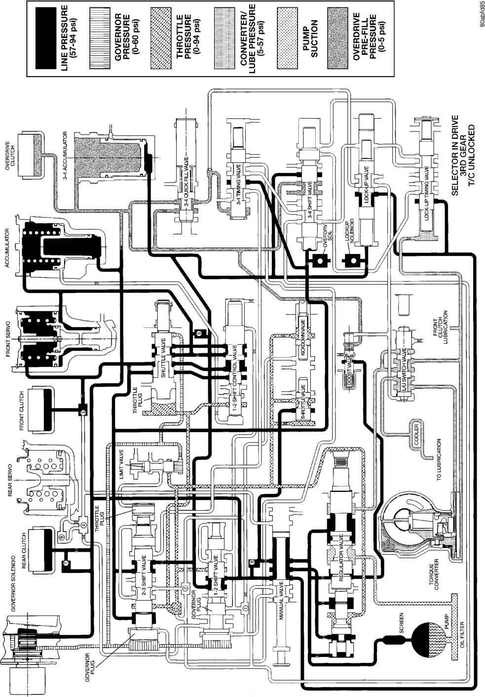

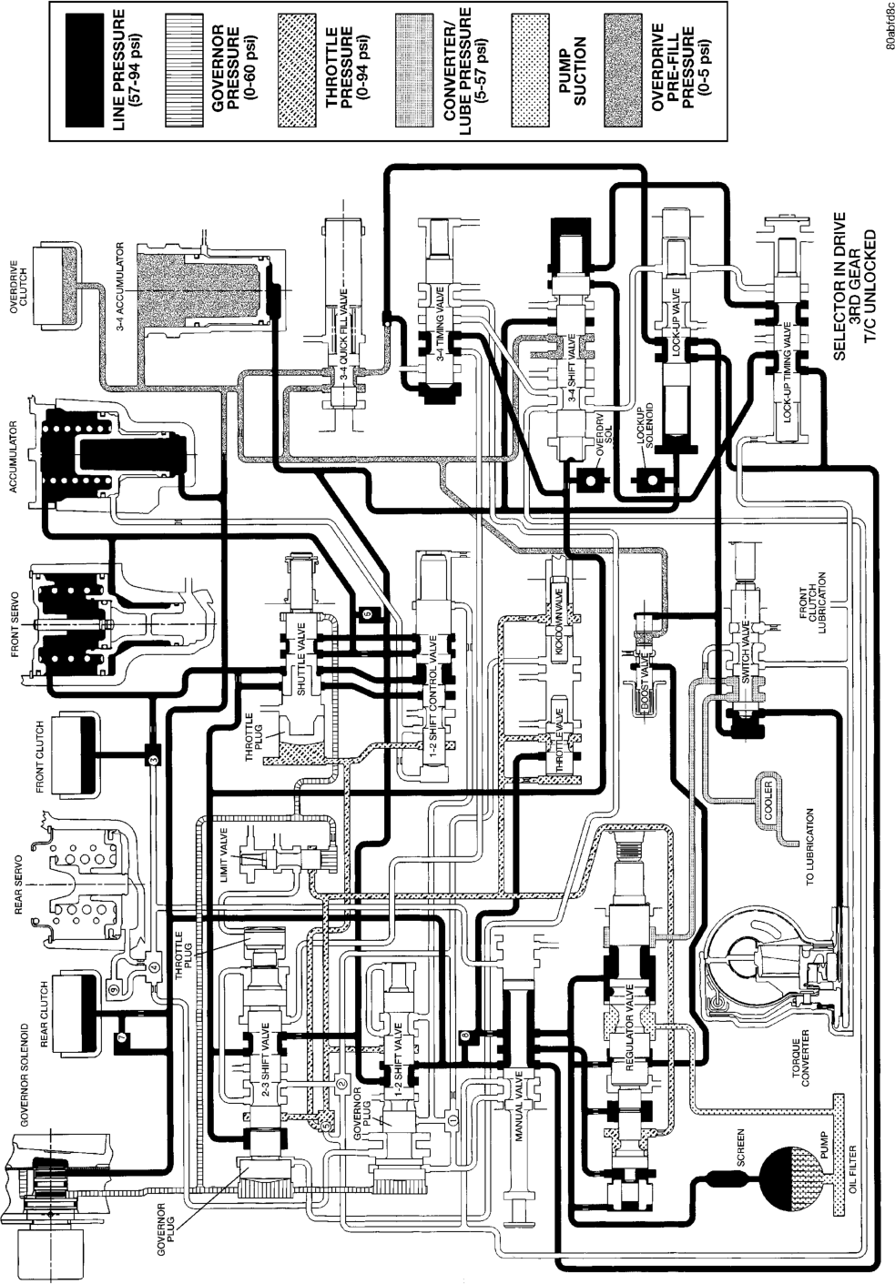

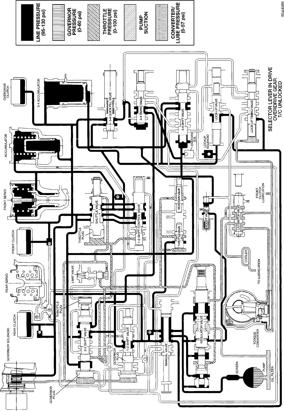

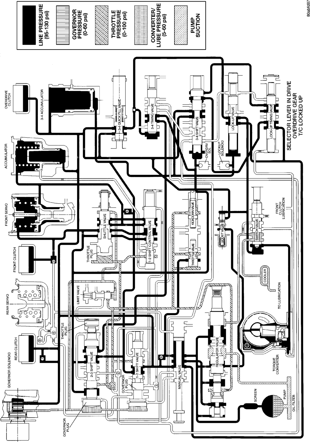

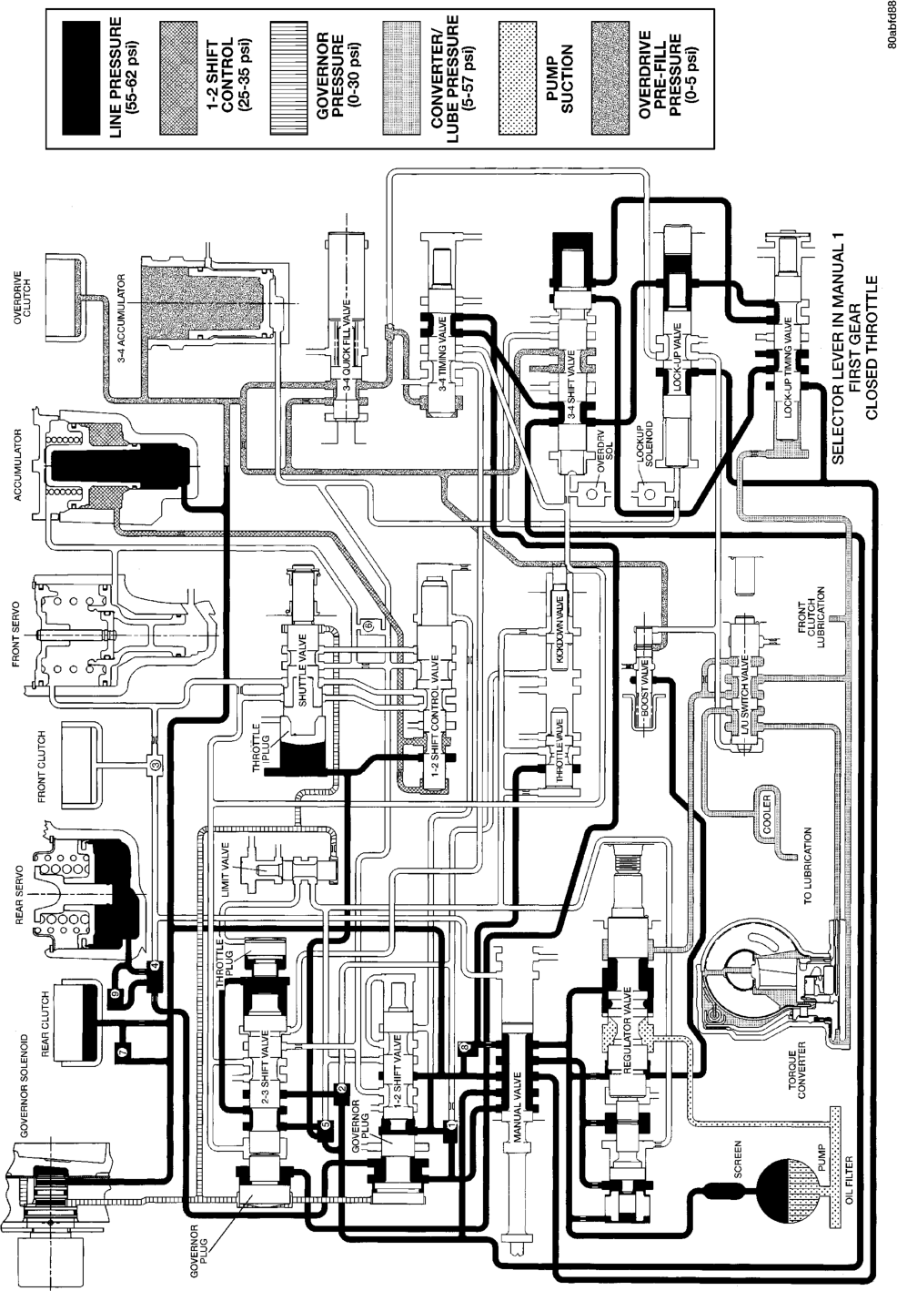



SPECIFICATIONS
RE TRANSMISSION
GENERAL
0.089-0.190
0.004-0.008 in.
Oil pump gear tip clearance mm

Clutch pack

clearance/Front
3-disc.
0.64-1.14 mm | 0.025-0.045 in.
Clutch pack clearance/Rear
4-disc.
Overdrive clutch disc
4 discs usage
Direct clutch disc
8 discs usage
Front clutch spring
9 spring usage
Band adjustment from 72 In. Ibs.
Front band | Back off 2-7/8 turns
Rear band | Back off 2 turns
Recommended fluid | Mopar‘
ATF Plus, type 7176

TORQUE
DESCRIPTION TORQUE Bolt, torque convertor . . . . . . . . . .31 N·m (23 ft. lbs.) Bolt/nut, crossmember . . . . . . . . .68 N·m (50 ft. lbs.) Bolt, driveplate to crankshaft . . . .75 N·m (55 ft. lbs.) Plug, front band reaction . . . . . . .17 N·m (13 ft. lbs.) Locknut, front band adj. . . . . . . . .34 N·m (25 ft. lbs.) Switch, park/neutral . . . . . . . . . . .34 N·m (25 ft. lbs.) Bolt, fluid pan. . . . . . . . . . . . . . . .17 N·m (13 ft. lbs.) Bolt, oil pump . . . . . . . . . . . . . . . .20 N·m (15 ft. lbs.) Bolt, overrunning clutch cam . . . .17 N·m (13 ft. lbs.) Bolt, O/D to trans. . . . . . . . . . . . .34 N·m (25 ft. lbs.) Bolt, O/D piston retainer . . . . . . .17 N·m (13 ft. lbs.) Plug, pressure test port . . . . . . . .14 N·m (10 ft. lbs.) Bolt, reaction shaft support . . . . .20 N·m (15 ft. lbs.) Locknut, rear band . . . . . . . . . . . .41 N·m (30 ft. lbs.) Bolt. speedometer adapter . . . . . . .11 N·m (8 ft. lbs.) Screw, fluid filter . . . . . . . . . . . . . .4 N·m (35 in. lbs.) Bolt, valve body to case . . . . . . .12 N·m (100 in. lbs.)
THRUST WASHER/SPACER/SNAP RING DIMENSIONS
Front clutch thrust washer (reaction shaft 1.55 mm 0.061 in. support hub) 2.15 mm 0.084 in. 0.102 in.
Rear clutch thrust washer (clutch retainer) 1.55 mm 0.061 in.
Output shaft thrust plate (output shaft pilot hub) 1.5-1.6 mm 0.060-0.063 in.
Output shaft thrust washer (rear clutch hub) 1.3-1.4 mm 0.052-0.054 in. 1.75-1.8 mm 0.068-0.070 in. 2.1-2.2 mm 0.083-0.085 in.
Rear clutch pack snap ring 1.5-1.6 mm 0.060-0.062 in. 1.9-1.95 mm 0.074-0.076 in.
Planetary geartrain snap ring 1.4-1.5 mm 0.055-0.059 in. (at front of output shaft) 1.6-1.7 mm 0.062-0.066 in.
Overdrive piston thrust plate Thrust plate and spacer are select fit components. Refer to size charts and
Intermediate shaft spacer selection procedures in Overdrive Unit disassembly and assembly section.
PRESSURE TEST
Overdrive clutch Fourth gear only Pressure should be 469-496 kPa (68-72 psi) with closed throttle and increase to 620-896 kPa (90-130 psi) at 1/2 to 3/4 throttle.
Line pressure (at accumulator)
Closed throttle 372-414 kPa (54-60 psi).
Front servo Third gear only No more than 21 kPa (3 psi) lower than line pressure.
Rear servo 1 range No more than 21 kPa (3 psi) lower than line pressure.
Governor D range closed throttle Pressure should respond smoothly to changes in mph and return to 0-7 kPa (0-1.5 psi) when stopped with transmission in D, 1, 2. Pressure above 7 kPa (1.5 psi) at stand still will prevent transmission from downshifting.
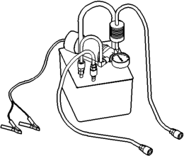
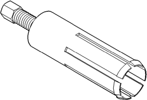
SPECIAL TOOLS
RE TRANSMISSION
R range 1103 kPa (160 psi) at idle, builds to 1862 kPa (270 psi) at 1600 rpm.
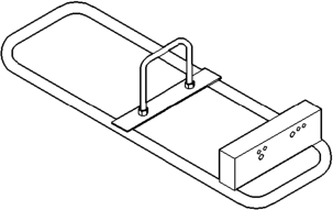

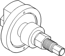

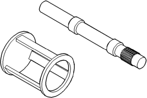



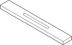

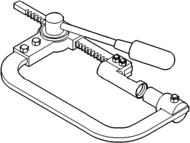

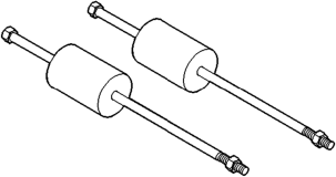

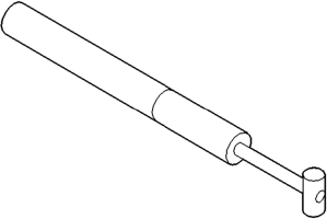




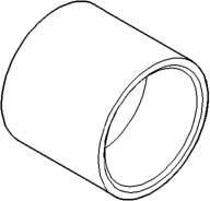

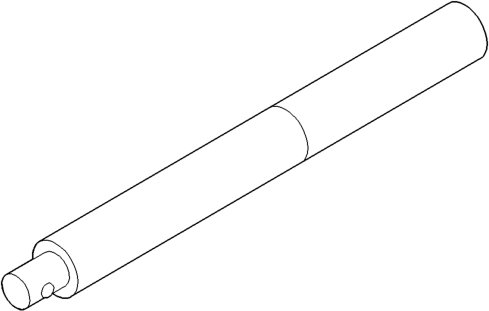


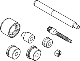


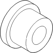


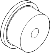

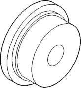


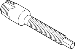



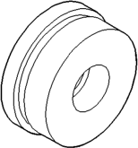

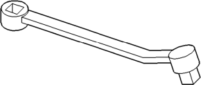

GENERAL INFORMATION
NV242 TRANSFER CASE . . . . . . . . . . . . . . . . . 241 RECOMMENDED LUBRICANT AND
FILL LEVEL . . . . . . . . . . . . . . . . . . . . . . . . . . 242 TRANSFER CASE IDENTIFICATION . . . . . . . . . 241 DIAGNOSIS AND TESTING
NV242 DIAGNOSIS . . . . . . . . . . . . . . . . . . . . . 242 REMOVAL AND INSTALLATION
FRONT OUTPUT SHAFT SEAL . . . . . . . . . . . . 244 SHIFT LEVER . . . . . . . . . . . . . . . . . . . . . . . . . . 243 SPEEDOMETER . . . . . . . . . . . . . . . . . . . . . . . . 243
GENERAL INFORMATION
NV242 TRANSFER CASE
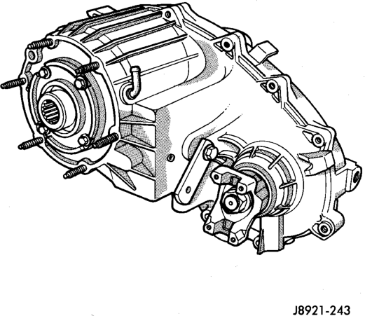
The NV242 is a full and part-time transfer case (Fig. 1). It provides full time 2-wheel, or 4-wheel drive operation.
A differential in the transfer case is used to control torque transfer to the front and rear axles. A low range gear provides increased low speed torque capability for off road operation. The low range provides a 2.72:1 reduction ratio.
The input gear is splined to the transmission output shaft. It drives the mainshaft through the planetary gear and range hub. The front output shaft is
NV242 TRANSFER CASE
INDEX
page page
TRANSFER CASE . . . . . . . . . . . . . . . . . . . . . . 243 DISASSEMBLY AND ASSEMBLY
NV242 TRANSFER CASE . . . . . . . . . . . . . . . . . 245 CLEANING AND INSPECTION
NV242 TRANSFER CASE . . . . . . . . . . . . . . . . . 265 ADJUSTMENTS
SHIFT LINKAGE ADJUSTMENT . . . . . . . . . . . . 268 SPECIFICATIONS
TORQUE . . . . . . . . . . . . . . . . . . . . . . . . . . . . . 268 SPECIAL TOOLS
SPECIAL TOOLS—NV242 . . . . . . . . . . . . . . . . 269 operated by a drive chain that connects the shaft to a drive sprocket on the mainshaft. The drive sprocket is engaged/disengaged by the mode fork, which operates the mode sleeve and hub. The sleeve and hub are not equipped with a synchro mechanism for shifting. The geartrain is mounted in two aluminum case halves attached with bolts. The mainshaft front and rear bearings are mounted in aluminum retainer housings bolted to the case halves.
OPERATING RANGES
NV242 operating ranges are 2WD (2-wheel drive), 4x4 part-time, 4x4 full time, and 4 Lo.
The 2WD and 4x4 full time ranges can be used at any time and on any road surface.
The 4x4 part-time and 4 Lo ranges are for off road use only. The only time these ranges can be used on hard surface roads, is when the surface is covered with snow and ice.
SHIFT MECHANISM
Operating ranges are selected with a floor mounted shift lever. The shift lever is connected to the transfer case range lever by an adjustable linkage rod. A straight line shift pattern is used. Range positions are marked on the shifter bezel cover plate, or on the shift knob.
TRANSFER CASE IDENTIFICATION
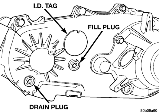
A circular ID tag is attached to the rear case of each transfer case (Fig. 2). The ID tag provides the transfer case model number, assembly number, serial number, and low range ratio.
The transfer case serial number also represents the date of build.
DIAGNOSIS AND TESTING
NV242 DIAGNOSIS
Transfer case difficult to shift or will not shift into desired range.
1) Transfer case shift linkage binding.
3) Internal transfer case components binding, worn, or damaged.
Transfer case noisy in all drive modes.
Lubricant leaking from transfer case seals or vent.
2) Transfer case vent closed or restricted.
Transfer case will not shift through 4X4 part time range (light remains on)
RECOMMENDED LUBRICANT AND FILL LEVEL
Recommended lubricant for the NV242 transfer case is Mopart Dexron II, or ATF Plus, type 7176. Approximate lubricant fill capacity is 1.35 liters (2.85 pints).
The fill and drain plugs are both in the rear case (Fig. 2). Correct fill level is to the bottom edge of the fill plug hole. Be sure the vehicle is level to ensure an accurate fluid level check.
DIAGNOSIS CHART
Condition Possible Cause Correction
1) Repair or replace linkage as necessary.
2) Insufficient or incorrect lubricant. 3) Drain and refill transfer case with the correct type and quantity of lubricant.
3) Repair or replace components as necessary.
1) Insufficient or incorrect lubricant. 1) Drain and refill transfer case with the correct type and quantity of lubricant.
1) Transfer case overfilled. 1) Drain lubricant to the correct level.
2) Clean or replace vent as necessary.
3) Transfer case seals damaged or installed incorrectly. 3) Replace suspect seal.
1) Incomplete shift due to drivetrain torque load.
1) Momentarily release the accelerator pedal to complete the shift.
2) Incorrect tire pressure. 2) Correct tire pressure as necessary.
3) Excessive Tire wear. 3) Correct tire condition as necessary.
4) Excessive vehicle loading. 4) Correct as necessary.
REMOVAL AND INSTALLATION
TRANSFER CASE
REMOVAL
(1) Shift transfer case into Neutral. (2) Raise vehicle. (3) Drain transfer case lubricant. (4) Mark front and rear propeller shaft yokes for alignment reference.
(5) Support transmission with jack stand. (6) Remove rear crossmember, or skid plate. (7) Disconnect front/rear propeller shafts at transfer case.
(8) Disconnect vehicle speed sensor wires. (9) Disconnect transfer case linkage rod from range lever.
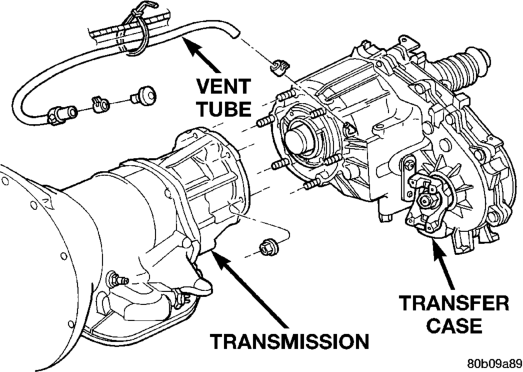
(10) Disconnect transfer case vent hose (Fig. 3) and indicator switch harness, if necessary.
(11) Support transfer case with transmission jack. (12) Secure transfer case to jack with chains. (13) Remove nuts attaching transfer case to transmission.
(14) Pull transfer case and jack rearward to disengage transfer case.
(15) Remove transfer case from under vehicle.
INSTALLATION
(1) Mount transfer case on a transmission jack. (2) Secure transfer case to jack with chains. (3) Position transfer case under vehicle. (4) Align transfer case and transmission shafts and install transfer case on transmission.
(5) Install and tighten transfer case attaching nuts to 35 N·m (26 ft. lbs.) torque (Fig. 3).
(6) Connect vehicle speed sensor wires, and vent hose.
(7) Connect indicator switch harness to transfer case switch, if necessary. Secure wire harness to clips on transfer case.
(8) Align and connect propeller shafts. Refer to Group 3, Differential and Driveline, for proper procedures and specifications.
(9) Fill transfer case with correct fluid. Check transmission fluid level. Correct as necessary.
(10) Install rear crossmember, or skid plate. Tighten crossmember bolts to 41 N·m (30 ft. lbs.) torque.
(11) Remove transmission jack and support stand. (12) Connect shift rod to transfer case range lever. (13) Adjust transfer case shift linkage. (14) Lower vehicle and verify transfer case shift operation.
SHIFT LEVER
REMOVAL
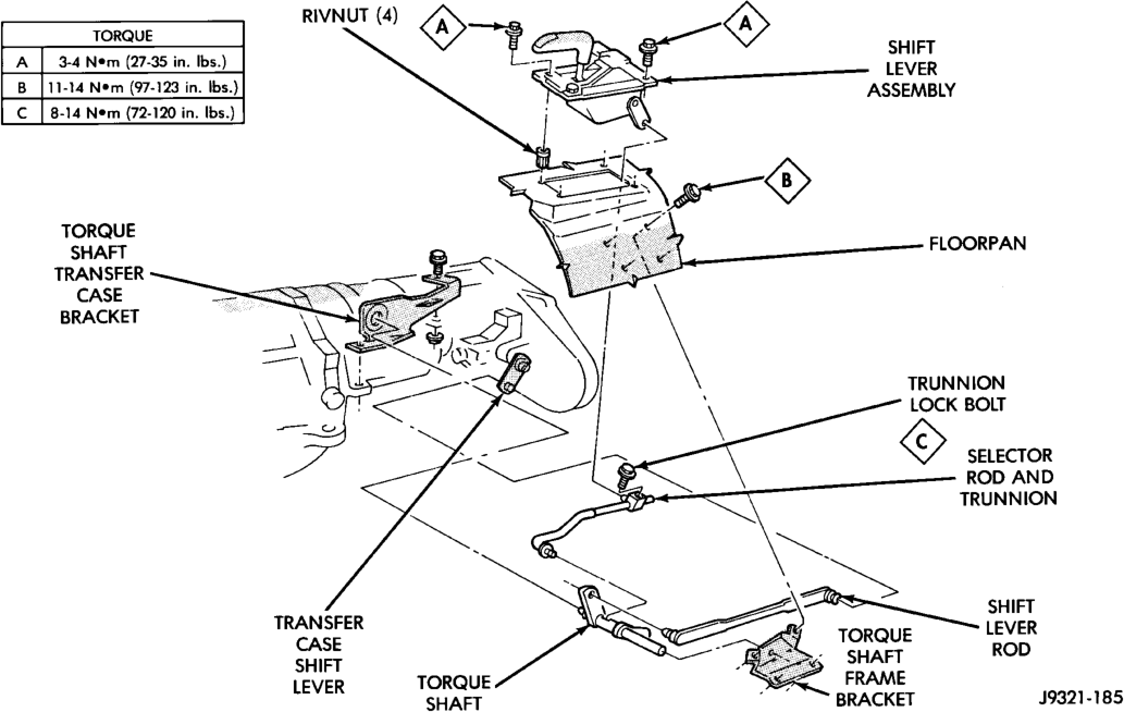
(1) Shift transfer case into 4L. (2) Raise vehicle. (3) Loosen adjusting trunnion locknut and slide shift rod out of trunnion (Fig. 4). If rod lacks enough travel to come out of trunnion, push trunnion out of torque shaft.
(4) Lower vehicle. (5) Remove console. Refer to Group 23, Body, for proper procedures.
(6) Remove screws attaching lever assembly to floorpan and remove assembly and shift rod (if left attached).
INSTALLATION
(1) If shift rod was not removed from lever assembly, work rod down through floorpan opening. Then position lever assembly on floorpan and install assembly attaching screws.
(2) Install console. Refer to Group 23, Body, for proper procedures.
(3) Raise vehicle. (4) Connect trunnion to torque shaft arm. Or, slide shift rod into trunnion on range lever. Be sure shift rod slides freely in trunnion.
(5) Verify that range lever is in 4L position. Then tighten trunnion lock bolt.
(6) Lower vehicle and check transfer case shift operation.
SPEEDOMETER
REMOVAL
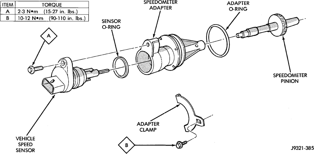
(1) Raise vehicle. (2) Disconnect wires from vehicle speed sensor. (3) Remove adapter clamp and screw (Fig. 5). (4) Remove speed sensor and speedometer adapter as an assembly.
(5) Remove speed sensor retaining screw and remove sensor from adapter.
(6) Remove speedometer pinion from adapter. Replace pinion if chipped, cracked, or worn.
(7) Inspect sensor and adapter O-rings (Fig. 5). Remove and discard O-rings if worn or damaged.
(8) Inspect terminal pins in speed sensor. Clean pins with Mopart electrical spray cleaner if dirty or oxidized. Replace sensor if faulty, or if pins are loose, severely corroded, or damaged.
INSTALLATION AND INDEXING
(1) Thoroughly clean adapter flange and adapter mounting surface in housing. Surfaces must be clean for proper adapter alignment and speedometer operation.
(2) Install new O-rings on speed sensor and speedometer adapter (Fig. 5), if necessary.
(3) Lubricate sensor and adapter O-rings with transmission fluid.
(4) Install vehicle speed sensor in speedometer adapter. Tighten sensor attaching screw to 2-3 N·m (15-27 in. lbs.) torque.
(5) Install speedometer pinion in adapter. (6) Count number of teeth on speedometer pinion. Do this before installing assembly in housing. Then lubricate pinion teeth with transmission fluid.
(7) Note index numbers on adapter body (Fig. 6). These numbers will correspond to number of teeth on pinion.
(8) Install speedometer assembly in housing. (9) Rotate adapter until required range numbers are at 6 o-clock position. Be sure range index numbers correspond to number of teeth on pinion gear.
(10) Install speedometer adapter clamp and retaining screw. Tighten clamp screw to 10-12 N·m (90-110 in. lbs.) torque. (11) Connect wires to vehicle speed sensor. (12) Lower vehicle and top off transmission fluid level if necessary.
FRONT OUTPUT SHAFT SEAL
REMOVAL
(1) Raise vehicle. (2) Remove front propeller shaft. Refer to Group 3, Differential and Driveline, for proper procedure.
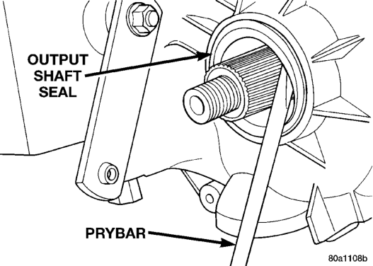
(3) Remove front output shaft yoke. (4) Remove seal from front case with pry tool (Fig. 7).
Adapter
INSTALLATION
(1) Install new front output seal in front case with Installer Tool 6952-A as follows:
(a) Place new seal on tool. Garter spring on seal goes toward interior of case.
(b) Start seal in bore with light taps from hammer (Fig. 8). Once seal is started, continue tapping seal into bore until installer tool seats against case.
DISASSEMBLY AND ASSEMBLY
NV242 TRANSFER CASE
DISASSEMBLY
REAR RETAINER REMOVAL
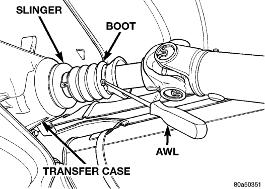
(1) Remove output shaft boot. Spread band clamp that secures boot on slinger with a suitable awl. Then slide boot off shaft (Fig. 9).
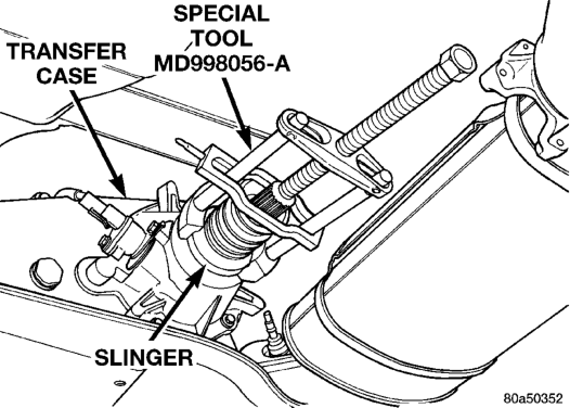
(2) Using puller MD-998056-A, remove rear slinger (Fig. 10).
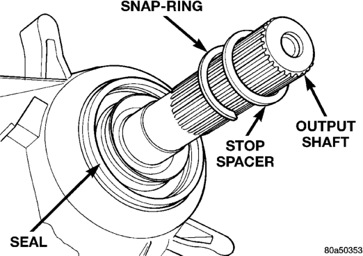
(3) Remove slinger stop spacer and snap-ring from output shaft (Fig. 11).
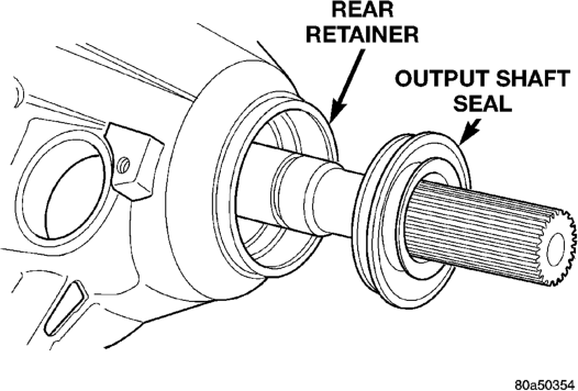
(4) Remove rear seal from retainer (Fig. 12). Use pry tool, or collapse seal with punch to remove it.
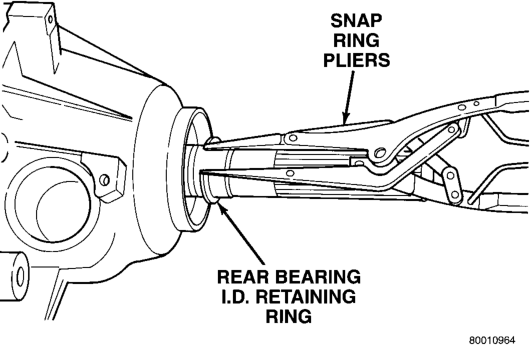
(5) Remove rear output bearing I.D. retaining ring (Fig. 13).
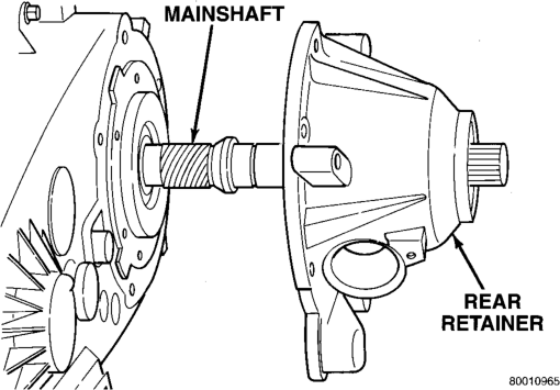
(6) Remove speedometer adapter. (7) Remove rear retainer bolts. (8) Remove rear retainer. Tap retainer with mallet and pry upward to break sealer bead. Then slide retainer off case and output shaft (Fig. 14).
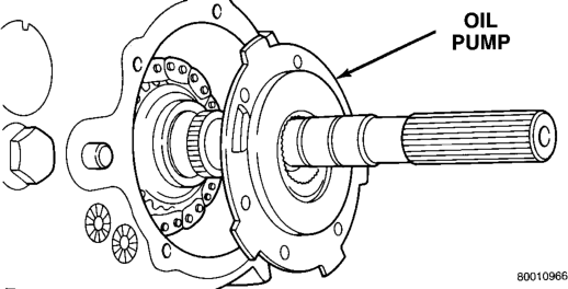
(9) Remove rear bearing O.D. retaining ring with snap ring pliers. Then tilt pump and slide it off output shaft (Fig. 15)
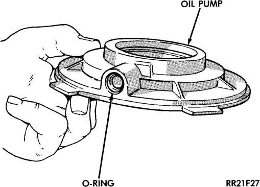
(10) Remove pickup tube O-ring from pump (Fig. 16) but do not disassemble pump; it is not a repairable part.
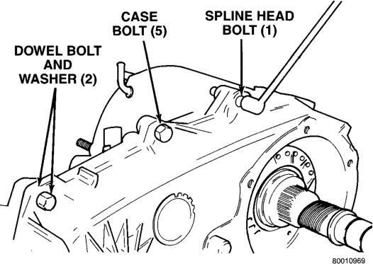
(11) Remove seal from oil pump with pry tool. (12) Remove bolts attaching rear case to front case (Fig. 17). Note position of the two black finish bolts at each end of the case. These bolts go through the case dowels and require a washer under the bolt head.
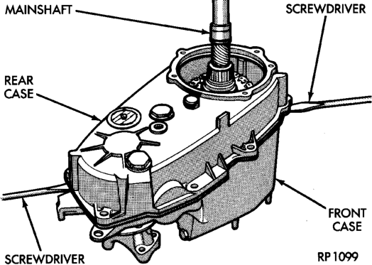
(13) Remove rear case from front case (Fig. 18). Insert screwdrivers into slots cast into each end of case. Then pry upward to break sealer bead and remove rear case.
CAUTION: Do not pry on the sealing surface of either case half as the surfaces will become damaged.
(14) Remove oil pickup tube and screen from rear case (Fig. 19).