Vehicle Theft/Security Systems — 1998 Jeep Grand Cherokee ZJ Export Service Manual
Pages 489–509 · 20 pages · 8 words repaired
ARMING
Passive arming of the Vehicle Theft Security System (VTSS) occurs when the vehicle is exited with the key removed from the ignition switch, the headlamps are turned off, and the doors are locked using the power lock switch. The power lock switch will not function if the key is in the ignition switch or the headlamps are on with the driver side front door open. The VTSS will not arm if either front door or the liftgate are locked using the key in the lock cylinder or using the mechanical lock button. Active arming of the VTSS occurs when the Remote Keyless Entry (RKE) transmitter is used to lock the vehicle, even if the doors and/or the liftgate are open when the RKE transmitter Lock button is depressed. However, the VTSS arming will not be complete until all of the doors and the liftgate are closed.
Following successful passive or active VTSS arming, the VTSS set lamp on the top of the instrument panel will flash rapidly for about fifteen seconds after the illuminated entry system times out. This indicates that VTSS arming is in progress. Once the fifteen second arming function is successfully completed, the set lamp will flash at a slower rate to indicate that the VTSS is armed.
DISARMING
Passive disarming of the Vehicle Theft Security System (VTSS) occurs when the vehicle is unlocked using the key to unlock either front door or the liftgate. Active disarming of the VTSS occurs when the vehicle is unlocked by depressing the Unlock button of the Remote Keyless Entry (RKE) transmitter.
Once the alarm has been activated (horn sounding, exterior lamps flashing, and the engine no-run feature), either disarming method will also deactivate the alarm.
Depressing the Panic button on the RKE transmitter will also disarm the VTSS, but the horn will sound and the exterior lamps will flash for about three minutes as part of the Panic feature function. Refer to Group 8P - Power Lock Systems for more information on the Panic feature.
POWER-UP MODE
When the armed Vehicle Theft Security System (VTSS) senses that the battery has been disconnected and reconnected, it enters its power-up mode. In the power-up mode the alarm system remains armed following a battery failure or disconnect. If the VTSS was armed prior to a battery disconnect or failure, the system will have to be actively or passively disarmed after the battery is reconnected.
The power-up mode will also apply if the battery goes dead while the system is armed, and battery jump-starting is attempted. The engine no-run feature will prevent the engine from starting until the alarm system has been actively or passively disarmed.
TAMPER ALERT
The Vehicle Theft Security System (VTSS) tamper alert will sound the horn three times upon disarming, if the alarm was activated and has since timedout (about eighteen minutes). This feature alerts the vehicle operator that the VTSS was activated while the vehicle was unattended.
DESCRIPTION AND OPERATION
BODY CONTROL MODULE
A Body Control Module (BCM) is used on this model to control and integrate many of the electronic functions and features included on the vehicle. The BCM contains a central processing unit and interfaces with other modules in the vehicle on the Chrysler Collision Detection (CCD) data bus network.
The CCD data bus network allows the sharing of sensor information. This helps to reduce wire harness complexity, reduce internal controller hardware, and reduce component sensor current loads. At the same time, this system provides increased reliability, enhanced diagnostics, and allows the addition of many new feature capabilities.
One of the functions and features that the BCM supports and controls, is the Vehicle Theft Security System (VTSS). In the VTSS, the BCM receives CCD message inputs from the Passenger Door Module (PDM), which contains the Remote Keyless Entry (RKE) receiver. In addition to the information received on the CCD data bus, the BCM receives hard-wired inputs from the door ajar, door lock cylinder, ignition, liftgate ajar, liftgate lock cylinder, and liftglass ajar switches. The programming in the BCM allows it to process the information from all of its inputs and send control outputs to energize or de-energize the auto headlamp relay, horn relay, park lamp relay, Powertrain Control Module (PCM), and the security set lamp.
The BCM is mounted under the driver side outboard end of the instrument panel, behind the instrument panel support armature and below the outboard switch pod. Refer to Group 8E - Instrument Panel Systems for the removal and installation procedures. For diagnosis of the BCM or the CCD data bus, the use of a DRB scan tool and the proper Diagnostic Procedures manual are recommended. The BCM can only be serviced by an authorized electronic repair station. Refer to the latest Warranty Policies and Procedures manual for a current listing of authorized electronic repair stations.
DOOR AJAR SWITCH
The door ajar switches are mounted to the pillar in the rear of each door opening. They are plunger-type switches that are case grounded to the pillar. When the door is open the switch is closed, and when the door is closed the switch is open.
The door ajar switches cannot be repaired and, if faulty or damaged, they must be replaced.
DOOR LOCK CYLINDER SWITCH
The door lock cylinder switches are mounted to the back of the key lock cylinder inside each front door. They are normally-open momentary switches that close to ground only when the lock cylinder is rotated to the unlock position.
The door lock cylinder switches cannot be repaired and, if faulty or damaged, they must be replaced.
LIFTGATE AJAR SWITCH
The liftgate ajar switch is integral to the liftgate latch assembly on the liftgate. It is a momentarytype switch that is open when the liftgate is closed, and closed when the liftgate is open.
The liftgate ajar switch cannot be repaired and, if faulty or damaged, the liftgate latch assembly must be replaced.
LIFTGATE LOCK CYLINDER SWITCH
The liftgate lock cylinder switch is mounted to the back of the key lock cylinder inside the liftgate. It is a normally-open momentary switch that closes to ground only when the lock cylinder is rotated to the unlock position.
The liftgate lock cylinder switch cannot be repaired and, if faulty or damaged, it must be replaced.
LIFTGLASS AJAR SWITCH
The liftglass ajar switch is integral to the liftglass latch assembly on the liftgate. It is a momentarytype switch that is open when the liftglass is closed, and closed when the liftglass is open.
The liftglass ajar switch cannot be repaired and, if faulty or damaged, the liftglass latch assembly must be replaced.
AUTO HEADLAMP RELAY
The auto headlamp relay is a International Standards Organization (ISO) micro-relay. The terminal designations and functions are the same as a conventional ISO relay. However, the micro-relay terminal orientation (or footprint) is different, current capacity is lower, and the relay case dimensions are smaller than those of the conventional ISO relay.
The auto headlamp relay is a electromechanical device that switches battery current to the headlamps when the Body Control Module (BCM) grounds the relay coil. See the Diagnosis and Testing section of this group for more information on the operation of the auto headlamp relay.
The auto headlamp relay is located in the junction block, on the right cowl side inner panel below the instrument panel in the passenger compartment. The auto headlamp relay cannot be repaired and, if faulty or damaged, it must be replaced.
HORN RELAY
The horn relay is a International Standards Organization (ISO) micro-relay. The terminal designations and functions are the same as a conventional ISO relay. However, the micro-relay terminal orientation (or footprint) is different, current capacity is lower, and the relay case dimensions are smaller than those of the conventional ISO relay.
The horn relay is a electromechanical device that switches battery current to the horn when the horn switch or the Body Control Module (BCM) grounds the relay coil. See the Diagnosis and Testing section of this group for more information on the operation of the horn relay.
The horn relay is located in the Power Distribution Center (PDC), in the engine compartment. Refer to the PDC label for relay identification and location.
If a problem is encountered with a continuously sounding horn, it can usually be quickly resolved by removing the horn relay from PDC until further diagnosis is completed.
The horn relay cannot be repaired and, if faulty or damaged, it must be replaced.
PARK LAMP RELAY
The park lamp relay is a International Standards Organization (ISO) micro-relay. The terminal designations and functions are the same as a conventional ISO relay. However, the micro-relay terminal orientation (or footprint) is different, current capacity is lower, and the relay case dimensions are smaller than those of the conventional ISO relay.
The park lamp relay is a electromechanical device that switches battery current to the park lamps when the Body Control Module (BCM) grounds the relay coil. See the Diagnosis and Testing section of this group for more information on the operation of the park lamp relay.
The park lamp relay is located in the junction block, on the right cowl side panel below the instrument panel in the passenger compartment. The park lamp relay can be accessed by removing the fuse access panel and the right cowl side trim panel.
The park lamp relay cannot be repaired and, if faulty or damaged, it must be replaced.
SET LAMP
The Vehicle Theft Security System (VTSS) set lamp is a red light-emitting diode mounted with the auto headlamp ambient light sensor on top of the instrument panel near the driver side defroster outlet. The set lamp receives fused battery feed at all times and is grounded by the Body Control Module (BCM) to give a visual indication of the VTSS status.
The set lamp cannot be repaired and, if damaged or faulty, the set lamp/auto headlamp ambient light sensor unit must be replaced.
DIAGNOSIS AND TESTING
VEHICLE THEFT SECURITY SYSTEM
WARNING: ON VEHICLES EQUIPPED WITH AIR- BAGS, REFER TO GROUP 8M - PASSIVE RESTRAINT SYSTEMS BEFORE ATTEMPTING ANY STEERING WHEEL, STEERING COLUMN, OR INSTRUMENT PANEL COMPONENT DIAGNOSIS OR SERVICE. FAILURE TO TAKE THE PROPER PRE- CAUTIONS COULD RESULT IN ACCIDENTAL AIR- BAG DEPLOYMENT AND POSSIBLE PERSONAL INJURY.
The Vehicle Theft Security System (VTSS) and the Chrysler Collision Detection (CCD) data bus network should be diagnosed using the DRB scan tool and the proper Diagnostic Procedures manual. The DRB scan tool will provide confirmation that the CCD data bus is functional, that the Body Control Module (BCM) is enabled and putting the proper messages on the CCD data bus, that the BCM is enabled and receiving the proper hard-wired inputs and sending the proper hard-wired outputs, and that the Powertrain Control Module (PCM) is enabled and receiving the CCD data bus messages from the BCM.
Refer to the proper Diagnostic Procedures manual and the Vehicle Theft Security System menu item on the DRB scan tool for the procedures. Refer to 8W-39 - Vehicle Theft Security System in Group 8W - Wiring Diagrams for complete circuit descriptions and diagrams.
RELAYS
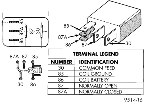
The horn relay is located in the Power Distribution Center (PDC) in the engine compartment. The auto headlamp and park lamp relays are located in the junction block in the passenger compartment. Each of these relays (Fig. 1) can be tested as described in the following procedure, however the circuits they are used in do vary. To test the relay circuits, refer to the circuit descriptions and diagrams in 8W-39 - Vehicle Theft Security System in Group 8W - Wiring Diagrams.
WARNING: ON VEHICLES EQUIPPED WITH AIR- BAGS, REFER TO GROUP 8M - PASSIVE RESTRAINT SYSTEMS BEFORE ATTEMPTING ANY STEERING WHEEL, STEERING COLUMN, OR INSTRUMENT PANEL COMPONENT DIAGNOSIS OR SERVICE. FAILURE TO TAKE THE PROPER PRE- CAUTIONS COULD RESULT IN ACCIDENTAL AIR- BAG DEPLOYMENT AND POSSIBLE PERSONAL INJURY.
Remove the relay from the PDC or junction block as described in this group to perform the following tests:
(1) A relay in the de-energized position should have continuity between terminals 87A and 30, and no continuity between terminals 87 and 30. If OK, go to Step 2. If not OK, replace the faulty relay.
(2) Resistance between terminals 85 and 86 (electromagnet) should be 75 6 5 ohms. If OK, go to Step 3. If not OK, replace the faulty relay.
(3) Connect a battery to terminals 85 and 86. There should now be continuity between terminals 30 and 87, and no continuity between terminals 87A and 30. If OK, test the relay circuits. If not OK, replace the faulty relay.
REMOVAL AND INSTALLATION
DOOR AJAR SWITCH
(1) Disconnect and isolate the battery negative cable.
(2) Remove the screw that secures the door ajar switch to the pillar at the rear of the door opening (Fig. 2).
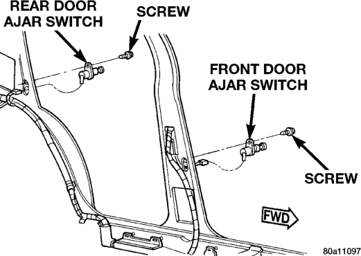
(3) Pull the switch out from the mounting hole in the door opening far enough to access the wire harness connector.
(4) Unplug the wire harness connector from the switch.
(5) Reverse the removal procedures to install. Tighten the switch mounting screw to 1.7 N·m (15 in. lbs.).
DOOR LOCK CYLINDER SWITCH
(1) Disconnect and isolate the battery negative cable.
(2) Remove the bezel near the inside door latch release handle by inserting a straight-bladed screwdriver in the notched end of the bezel and prying gently upwards.
(3) Remove the screw located beneath the bezel that secures the front door trim panel to the inner door panel (Fig. 3).
(4) Remove the trim cap and screw near the rear of the front door armrest.
(5) Remove the trim cap and screw at the upper front corner of the front door trim panel.
(6) Remove the screw located above the front door speaker grille on the front door trim panel.
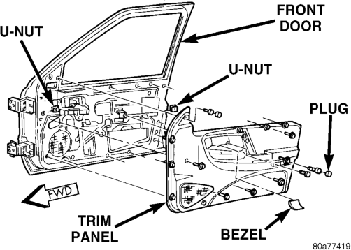
(7) Using a trim stick or another suitable wide flat-bladed tool, gently pry the front door trim panel away from the door around the perimeter to release the trim panel retainers.
NOTE: To aid in the removal of the trim panel, start at the bottom of the panel.
(8) Pull the front door trim panel away from the inner door panel far enough to access and unplug the wire harness connectors from the door module and, if the vehicle is so equipped, from the front door courtesy lamp.
(9) Pull the watershield away from the rear access holes in the front door inner panel.
(10) Remove the U-clip retainer that secures the lock cylinder to the outer door panel (Fig. 4).
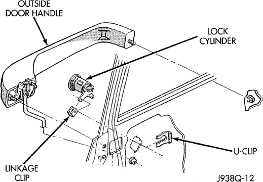
(11) Disconnect the door lock cylinder actuator rod from the door latch by unsnapping the plastic retainer.
(12) Pull the lock cylinder out of its mounting hole from the outside of the door panel far enough to pry the lock cylinder switch off of the back of the lock cylinder (Fig. 5).
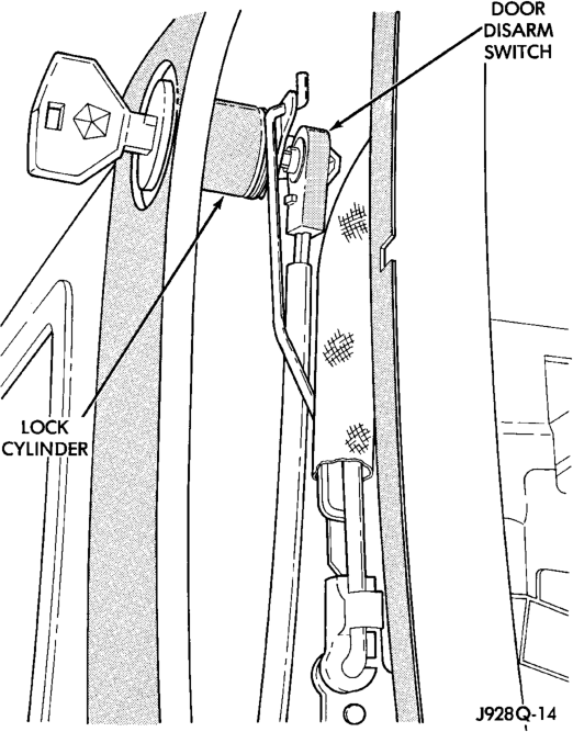
Typical
(13) From the inside of the door unplug the lock cylinder switch wire harness connector and remove the switch from the door.
(14) Reverse the removal procedures to install. Tighten the mounting screws to 2.2 N·m (20 in. lbs.).
LIFTGATE AJAR SWITCH
(1) Disconnect and isolate the battery negative cable.
(2) Open the liftgate. (3) Remove the screws that secure the liftgate lower trim panel to the liftgate inner panel (Fig. 6).
(4) Using a trim stick or another suitable wide flat-bladed tool, gently pry the perimeter edges of the trim panel away from the liftgate inner panel to release the retainers.
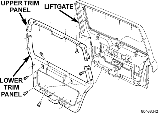
NOTE: To aid in the removal of the trim panel, start at the bottom of the panel.
(5) Remove the liftgate trim panel from the vehicle.
(6) Remove the three screws that secure the liftgate latch to the liftgate (Fig. 7).
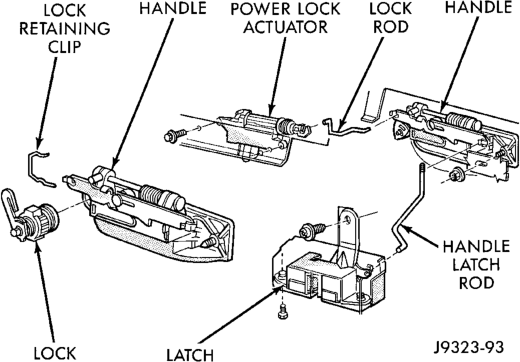
(7) Disconnect the liftgate handle latch actuator rod from the latch.
(8) Unplug the liftgate ajar switch wire harness connector from the latch.
(9) Remove the latch from the liftgate. (10) Reverse the removal procedures to install. Tighten the latch mounting screws to 7 N·m (62 in lbs.).
LIFTGATE LOCK CYLINDER SWITCH
(1) Disconnect and isolate the battery negative cable.
(2) Open the liftgate. (3) Remove the screws that secure the liftgate lower trim panel to the liftgate inner panel (Fig. 8).
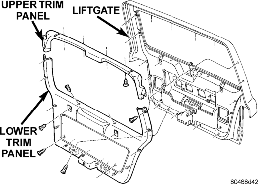
(4) Using a trim stick or another suitable wide flat-bladed tool, gently pry the perimeter edges of the trim panel away from the liftgate inner panel to release the retainers.
NOTE: To aid in the removal of the trim panel, start at the bottom of the panel.
(5) Remove the lower liftgate trim panel from the vehicle.
(6) Pry the liftgate lock cylinder switch off of the back of the lock cylinder (Fig. 9).
(7) Unplug the lock cylinder switch wire harness connector and remove the switch from inside the liftgate.
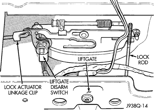
(8) Reverse the removal procedures to install. Tighten the mounting screws to 2.2 N·m (20 in. lbs.).
LIFTGLASS AJAR SWITCH
(1) Disconnect and isolate the battery negative cable.
(2) Open the liftgate. (3) Remove the screws that secure the liftgate lower trim panel to the liftgate inner panel (Fig. 10).
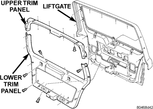
(4) Using a trim stick or another suitable wide flat-bladed tool, gently pry the perimeter edges of the trim panel away from the liftgate inner panel to release the retainers.
NOTE: To aid in the removal of the trim panel, start at the bottom of the panel.
(5) Remove the lower liftgate trim panel from the vehicle.
(6) Remove the two nuts that secure the liftglass latch to the liftgate inner panel (Fig. 11).
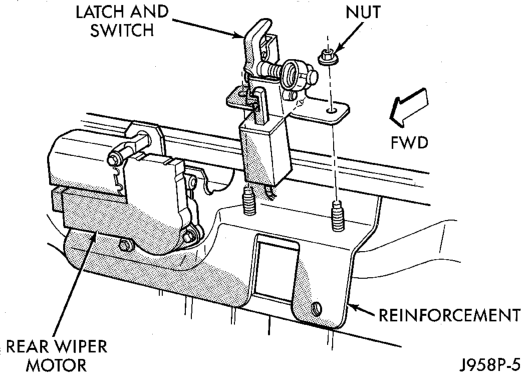
(7) Unplug the wire harness connectors for the liftglass latch solenoid and the liftglass ajar switch.
(8) Remove the liftglass latch from the liftgate. (9) Reverse the removal procedures to install. Tighten the latch mounting nuts to 11 N·m (100 in. lbs.). Tighten the trim panel mounting screws to 2.2 N·m (20 in. lbs.).
AUTO HEADLAMP AND PARK LAMP RELAYS
WARNING: ON VEHICLES EQUIPPED WITH AIR- BAGS, REFER TO GROUP 8M - PASSIVE RESTRAINT SYSTEMS BEFORE ATTEMPTING ANY STEERING WHEEL, STEERING COLUMN, OR INSTRUMENT PANEL COMPONENT DIAGNOSIS OR SERVICE. FAILURE TO TAKE THE PROPER PRE- CAUTIONS COULD RESULT IN ACCIDENTAL AIR- BAG DEPLOYMENT AND POSSIBLE PERSONAL INJURY.
(1) Disconnect and isolate the battery negative cable.
(2) Remove the fuse access panel by unsnapping it from the right cowl side trim panel.
(3) Remove the push nut that secures the right cowl side trim panel to the junction block stud (Fig. 12).
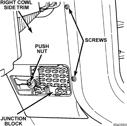
(4) Remove the two screws that secure the right cowl side trim panel to the right front door opening trim.
(5) Remove the right cowl side trim panel from the right cowl side inner panel.
(6) Unplug the headlamp or park lamp relay from the junction block.
(7) Install the headlamp or park lamp relay by aligning the relay terminals with the cavities in the junction block and pushing the relay firmly into place.
(8) Connect the battery negative cable. (9) Test the relay operation. (10) Reinstall the right cowl side trim and the fuse access panel.
HORN RELAY
(1) Disconnect and isolate the battery negative cable.
(2) Remove the cover from the Power Distribution Center (PDC) (Fig. 13).
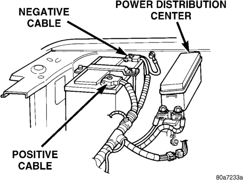
(3) Refer to the label on the PDC for horn relay identification and location. (4) Unplug the horn relay from the PDC. (5) Install the horn relay by aligning the relay terminals with the cavities in the PDC and pushing the relay firmly into place.
(6) Install the PDC cover. (7) Connect the battery negative cable. (8) Test the relay operation.
SET LAMP
WARNING: ON VEHICLES EQUIPPED WITH AIR- BAGS, REFER TO GROUP 8M - PASSIVE RESTRAINT SYSTEMS BEFORE ATTEMPTING ANY STEERING WHEEL, STEERING COLUMN, OR INSTRUMENT PANEL COMPONENT DIAGNOSIS OR SERVICE. FAILURE TO TAKE THE PROPER PRE- CAUTIONS COULD RESULT IN ACCIDENTAL AIR- BAG DEPLOYMENT AND POSSIBLE PERSONAL INJURY.
(1) Disconnect and isolate the battery negative cable.
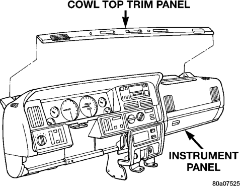
(2) Using a trim stick or another suitable wide flat-bladed tool, gently pry the cowl top trim panel off of the instrument panel top pad (Fig. 14).
(3) Pull the trim panel up far enough to access and unplug the wire harness connector for the solar sensor, or to remove the solar sensor from the cowl top trim, if the vehicle is so equipped.
(4) Remove the cowl top trim panel from the instrument panel. (5) Remove the auto headlamp light sensor/vehicle theft security system set lamp mounting screw near the driver side defroster duct outlet.
(6) Pull the set lamp up from the top of the instrument panel far enough to access and unplug the wire harness connector.
(7) remove the set lamp from the instrument panel.
(8) Reverse the removal procedures to install. Tighten the mounting screw to 2.2 N·m (20 in. lbs.).
DISARMING
Passive disarming of the VTSS occurs when the vehicle is unlocked using the key to unlock either front door or the liftgate. Active disarming of the VTSS occurs when the vehicle is unlocked by depressing the Unlock button of the RKE transmitter.
Once the alarm has been activated (horn sounding, lights flashing, and the engine no-run feature), either disarming method will also deactivate the alarm.
Depressing the Panic button on the RKE transmitter will also disarm the VTSS, but the horn will sound and the lights will flash for about three minutes as part of the Panic feature. Refer to Group 8P - Power Lock Systems for more information on the Panic feature.
POWER-UP MODE
When the armed VTSS senses that the battery has been disconnected and reconnected, it enters its power-up mode. In the power-up mode the alarm system remains armed following a battery failure or disconnect. If the VTSS was armed prior to a battery disconnect or failure, the system will have to be actively or passively disarmed following a battery reconnection.
The power-up mode will also apply if the battery goes dead while the system is armed, and battery jump-starting is attempted. The engine no-run feature will prevent the engine from starting until the alarm system has been actively or passively disarmed.
TAMPER ALERT
The Vehicle Theft Security System (VTSS) tamper alert will sound the horn three times upon disarming, if the alarm was activated and has since timedout (about eighteen minutes). This feature alerts the vehicle operator that the VTSS was activated while the vehicle was unattended.
DESCRIPTION AND OPERATION
BODY CONTROL MODULE
A Body Control Module (BCM) is used on this model to control and integrate many of the electronic functions and features included on the vehicle. The BCM contains a central processing unit and interfaces with other modules in the vehicle on the Chrysler Collision Detection (CCD) data bus network.
The CCD data bus network allows the sharing of sensor information. This helps to reduce wire harness complexity, reduce internal controller hardware, and reduce component sensor current loads. At the same time, this system provides increased reliability, enhanced diagnostics, and allows the addition of many new feature capabilities.
One of the functions and features that the BCM supports and controls, is the Vehicle Theft Security System (VTSS). In the VTSS, the BCM receives CCD message inputs from the Passenger Door Module (PDM), which contains the Remote Keyless Entry (RKE) receiver. In addition to the information received on the CCD data bus, the BCM receives hard-wired inputs from the door ajar, door lock cylinder, ignition, liftgate ajar, liftgate lock cylinder, and liftglass ajar switches. The programming in the BCM allows it to process the information from all of its inputs and send control outputs to energize or de-energize the auto headlamp relay, horn relay, park lamp relay, Powertrain Control Module (PCM), and the security set lamp.
The BCM is mounted under the driver side outboard end of the instrument panel, behind the instrument panel support armature and below the outboard switch pod. Refer to Group 8E - Instrument Panel Systems for the removal and installation procedures. For diagnosis of the BCM or the CCD data bus, the use of a DRB scan tool and the proper Diagnostic Procedures manual are recommended. The BCM can only be serviced by an authorized electronic repair station. Refer to the latest Warranty Policies and Procedures manual for a current listing of authorized electronic repair stations.
HOOD SWITCH
The hood switch is mounted to the right inner fender ledge, under the hood and near the battery. It is a plunger-type switch that is case grounded to the fender shield. When the hood is open the switch is closed, and when the hood is closed the switch is open.
The hood switch cannot be repaired and, if faulty or damaged, it must be replaced.
DOOR AJAR SWITCH
The door ajar switches are mounted to the pillar in the rear of each door opening. They are plunger-type switches that are case grounded to the pillar. When the door is open the switch is closed, and when the door is closed the switch is open.
The door ajar switches cannot be repaired and, if faulty or damaged, they must be replaced.
DOOR LOCK CYLINDER SWITCH
The door lock cylinder switches are mounted to the back of the key lock cylinder inside each front door. They are normally-open momentary switches that close to ground only when the lock cylinder is rotated to the unlock position.
The door lock cylinder switches cannot be repaired and, if faulty or damaged, they must be replaced.
LIFTGATE AJAR SWITCH
The liftgate ajar switch is integral to the liftgate latch assembly on the liftgate. It is a momentarytype switch that is open when the liftgate is closed, and closed when the liftgate is open.
The liftgate ajar switch cannot be repaired and, if faulty or damaged, the liftgate latch assembly must be replaced.
LIFTGATE LOCK CYLINDER SWITCH
The liftgate lock cylinder switch is mounted to the back of the key lock cylinder inside the liftgate. It is a normally-open momentary switch that closes to ground only when the lock cylinder is rotated to the unlock position.
The liftgate lock cylinder switch cannot be repaired and, if faulty or damaged, it must be replaced.
LIFTGLASS AJAR SWITCH
The liftglass ajar switch is integral to the liftglass latch assembly on the liftgate. It is a momentarytype switch that is open when the liftglass is closed, and closed when the liftglass is open.
The liftglass ajar switch cannot be repaired and, if faulty or damaged, the liftglass latch assembly must be replaced.
AUTO HEADLAMP RELAY
The auto headlamp relay is a International Standards Organization (ISO) micro-relay. The terminal designations and functions are the same as a conventional ISO relay. However, the micro-relay terminal orientation (or footprint) is different, current capacity is lower, and the relay case dimensions are smaller than those of the conventional ISO relay.
The auto headlamp relay is a electromechanical device that switches battery current to the headlamps when the Body Control Module (BCM) grounds the relay coil. See Auto Headlamp Relay in the Diagnosis and Testing section of this group for more information.
The auto headlamp relay is located in the junction block, on the right cowl side inner panel below the instrument panel in the passenger compartment. The auto headlamp relay cannot be repaired and, if faulty or damaged, it must be replaced.
HORN RELAY
The horn relay is a International Standards Organization (ISO) micro-relay. The terminal designations and functions are the same as a conventional ISO relay. However, the micro-relay terminal orientation (or footprint) is different, current capacity is lower, and the relay case dimensions are smaller than those of the conventional ISO relay.
The horn relay is a electromechanical device that switches battery current to the horn when the horn switch or the Body Control Module (BCM) grounds the relay coil. See Horn Relay in the Diagnosis and Testing section of this group for more information.
The horn relay is located in the Power Distribution Center (PDC), in the engine compartment. Refer to the PDC label for relay identification and location.
If a problem is encountered with a continuously sounding horn, it can usually be quickly resolved by removing the horn relay from PDC until further diagnosis is completed.
The horn relay cannot be repaired and, if faulty or damaged, it must be replaced.
PARK LAMP RELAY
The park lamp relay is a International Standards Organization (ISO) micro-relay. The terminal designations and functions are the same as a conventional ISO relay. However, the micro-relay terminal orientation (or footprint) is different, current capacity is lower, and the relay case dimensions are smaller than those of the conventional ISO relay.
The park lamp relay is a electromechanical device that switches battery current to the park lamps when the Body Control Module (BCM) grounds the relay coil. See Park Lamp Relay in the Diagnosis and Testing section of this group for more information.
The park lamp relay is located in the junction block, on the right cowl side panel below the instrument panel in the passenger compartment. The park lamp relay can be accessed by removing the fuse access panel and the right cowl side trim panel.
The park lamp relay cannot be repaired and, if faulty or damaged, it must be replaced.
SET LAMP
The VTSS set lamp is a red light-emitting diode mounted with the auto headlamp ambient light sensor on top of the instrument panel near the driver's side defroster outlet. The set lamp receives fused battery feed at all times and is grounded by the body control module to give a visible indication of the VTSS status.
The set lamp cannot be repaired and, if damaged or faulty, the set lamp/auto headlamp ambient light sensor must be replaced as a unit.
IMMOBILIZER SYSTEM
The Immobilizer System prevents unauthorized operation of the vehicle by disabling the engine. The system will NOT allow the vehicle to start unless the UNLOCK button on the RKE transmitter is pressed. The system will be activated after turning the ignition switch to the OFF position and using one of the following methods.
(1) Press the LOCK button on the RKE transmitter.
(2) LOCK the doors by pressing a power lock button switch.
(3) LOCK the driver or passenger door using the key.
• The Security light will flash, for about 16 seconds, indicating that the engine will be disabled.
• The Security light remaining on, indicates the system is not operational.
• The Immobilizer will activate automatically within 10 minutes of the ignition switch being in the OFF position, whether the vehicle has been locked or unlocked.
• An attempt to start the vehicle without pressing the UNLOCK button on the RKE transmitter will result in a warning chime and the Security light flashing.
NOTE: The ignition switch must be in the OFF position in order for the system to be activated, whether the doors are closed or not.
IMMOBILIZER RECEIVER
The immobilizer receiver is programmed to respond to the Lock and Unlock radio signals issued by the immobilizer transmitters. The receiver will only respond to the radio signals of transmitters (up to four) whose vehicle access codes have been stored in the receiver's electronic memory. The receiver is programmed at the assembly plant with the vehicle access codes of the two transmitters that are shipped with the vehicle.
The immobilizer receiver also has a central processing unit, which contains the immobilizer system logic. The programming in the immobilizer receiver allows the system to learn and retain transmitter vehicle access codes, as well as to communicate with the Powertrain Control Module (PCM) and/or the DRB scan tool on the Chrysler Collision Detection (CCD) data bus network.
The CCD data bus network allows the sharing of sensor information. This helps to reduce wiring harness complexity, reduce internal controller hardware, and reduce component sensor current loads. At the same time, the CCD data bus network provides increased reliability and enhanced diagnostic capabilities. Each immobilizer transmitter has a different vehicle access code, which must be programmed into the memory of the immobilizer receiver in the vehicle in order to operate the immobilizer system. A DRB scan tool must be used to program new or additional transmitter vehicle access codes into the memory of the immobilizer receiver. Refer to the Vehicle Theft Security System menu item on the DRB scan tool for the procedures.
The immobilizer receiver recognizes the Lock and Unlock signals received from the programmed immobilizer transmitters. The receiver then uses the programmed immobilizer system logic to decide whether other monitored conditions are proper for an engine Lock or Unlock message to be sent. If the programmed conditions are met, the receiver responds by sending the proper message to the PCM on the CCD data bus. The PCM responds to the message by disabling or enabling the fuel injector driver circuitry within the PCM, which will inhibit engine operation.
The immobilizer receiver is mounted to the dash panel with a hook and loop fastener patch. It is located behind the instrument cluster and above the driver side end of the heater-A/C housing. The receiver is connected to the dash panel cross-body wiring harness.
For diagnosis of the vehicle immobilizer receiver or the CCD data bus, a DRB scan tool is required. Refer to the Vehicle Theft Security System menu item of the DRB scan tool for the procedures. The immobilizer receiver cannot be repaired and, if faulty, the unit must be replaced.
IMMOBILIZER TRANSMITTER
The vehicle immobilizer system includes two transmitters that are supplied with the vehicle when it is shipped from the factory. Each of the two transmitters is equipped with two buttons labeled with International Standards Organization (ISO) symbols for Lock, and Unlock. Two spare batteries (enough for one transmitter) are also shipped with the transmitters. The transmitters are equipped with a key ring and are designed to serve as a key fob. The operating range of the radio frequency transmitter signal is up to 7 meters (23 feet) from the immobilizer receiver.
Each transmitter has a different vehicle access code, which must be programmed into the memory of the immobilizer receiver in the vehicle in order to operate the immobilizer system. The two transmitters shipped with the vehicle have their vehicle access codes programmed into the receiver at the factory. A DRB scan tool must be used to program new or additional transmitter vehicle access codes into the memory of the immobilizer receiver. Refer to the Vehicle Theft Security System menu item on the DRB scan tool for the procedures.
Each transmitter operates on two Duracell DL2016 (or equivalent) batteries. Typical battery life is from one to two years.
POWER-UP MODE
When the vehicle immobilizer system senses that the vehicle battery has been disconnected and reconnected, it enters its power-up mode. If the immobilizer system was armed prior to the battery disconnect, the system remains armed when the battery is reconnected.
If the immobilizer system was disarmed prior to the battery disconnect, the system will remain disarmed if the battery is reconnected within five minutes. The system will passively arm itself when the battery is reconnected more than five minutes after a battery disconnect or failure. After any passive arming, the system will have to be actively disarmed using one of the transmitters.
The power-up mode logic also applies if the battery goes dead, and battery jump-starting is attempted. The engine no-run feature will prevent the engine from operating until the vehicle immobilizer system has been actively disarmed.
DIAGNOSIS AND TESTING
VEHICLE THEFT SECURITY SYSTEM
The vehicle theft security system should be diagnosed using the DRB scan tool and the proper Body Diagnostic Procedures Manual. Refer to 8W-39 - Vehicle Theft Security System in Group 8W - Wiring Diagrams for complete circuit descriptions and diagrams.
Self-Diagnostics
The vehicle theft security system has a self-diagnostic mode that can be entered using the DRB scan tool. Refer to the proper Body Diagnostic Procedures Manual for more information on this feature.
RELAYS
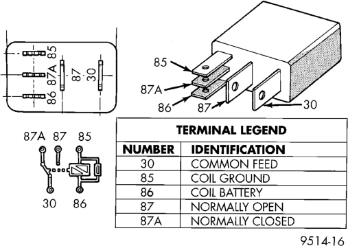
The horn relay is located in the Power Distribution Center (PDC) in the engine compartment. The auto headlamp and park lamp relays are located in the junction block in the passenger compartment. Each of these relays (Fig. 1) can be tested as described in the following procedure, however the circuits they are used in do vary. To test the relay circuits, refer to the circuit descriptions and diagrams in 8W-39 - Vehicle Theft Security System in Group 8W - Wiring Diagrams.
WARNING: ON VEHICLES EQUIPPED WITH AIR- BAGS, REFER TO GROUP 8M - PASSIVE RESTRAINT SYSTEMS BEFORE ATTEMPTING ANY STEERING WHEEL, STEERING COLUMN, OR INSTRUMENT PANEL COMPONENT DIAGNOSIS OR SERVICE. FAILURE TO TAKE THE PROPER PRE- CAUTIONS COULD RESULT IN ACCIDENTAL AIR-
BAG DEPLOYMENT AND POSSIBLE PERSONAL INJURY.
Remove the relay from the PDC or junction block as described in this group to perform the following tests:
(1) A relay in the de-energized position should have continuity between terminals 87A and 30, and no continuity between terminals 87 and 30. If OK, go to Step 3. If not OK, replace the faulty relay.
(2) Resistance between terminals 85 and 86 (electromagnet) should be 75 6 5 ohms. If OK, go to Step 4. If not OK, replace the faulty relay.
(3) Connect a battery to terminals 85 and 86. There should now be continuity between terminals 30 and 87, and no continuity between terminals 87A and 30. If OK, test the relay circuits. If not OK, replace the faulty relay.
SERVICE PROCEDURES
VEHICLE IMMOBILIZER SYSTEM
WARNING: ON VEHICLES EQUIPPED WITH AIR- BAGS, REFER TO GROUP 8M - PASSIVE RESTRAINT SYSTEMS BEFORE ATTEMPTING ANY STEERING WHEEL, STEERING COLUMN, OR INSTRUMENT PANEL COMPONENT DIAGNOSIS OR SERVICE. FAILURE TO TAKE THE PROPER PRE- CAUTIONS COULD RESULT IN ACCIDENTAL AIR- BAG DEPLOYMENT AND POSSIBLE PERSONAL INJURY.
NOTE: The following tests may not prove conclusive in the diagnosis of this system. The most reliable, efficient, and accurate means to diagnose the Vehicle Immobilizer System involves the use of a DRB scan tool. Refer to the Vehicle Theft Security System menu item on the DRB scan tool for the procedures.
The vehicle immobilizer system and the Chrysler Collision Detection (CCD) data bus network should be diagnosed using the DRB scan tool. The DRB will allow confirmation that the CCD data bus is functional, that the immobilizer receiver is placing the proper messages on the CCD data bus, and that the Powertrain Control Module (PCM) is receiving the CCD data bus messages. Refer to the Vehicle Theft Security System menu item on the DRB scan tool for the procedures. Refer to 8W-39 - Vehicle Theft Security System in Group 8W - Wiring Diagrams for complete circuit descriptions and diagrams.
(1) With the ignition switch in the Off position, depress the Lock or Unlock button of the immobilizer transmitter. Listen for the immobilizer receiver to issue an audible chirp (Unlock) or chirps (Lock). If OK, go to Step 3. If not OK, replace the transmitter batteries with known good units and repeat Step 2. If still not OK, go to Step 3.
(2) Check the fuse in the Power Distribution Center (PDC). If OK, go to Step 4. If not OK, repair the shorted circuit or component as required and replace the faulty fuse.
(3) Disconnect and isolate the battery negative cable. Unplug the wire harness connector at the immobilizer receiver. Check for continuity between the ground circuit cavity of the immobilizer receiver wire harness connector and a good ground. There should be continuity. If OK, go to Step 5. If not OK, repair the open circuit to ground as required.
(4) Connect the battery negative cable. Check for battery voltage at the fused B(+) circuit cavity of the immobilizer receiver wire harness connector. If OK, refer to the Vehicle Theft Security System menu item on the DRB scan tool for further diagnosis. If not OK, repair the open circuit to the PDC fuse as required.
ENABLING
The vehicle immobilizer system is disabled when it is shipped from the factory. This is done by programming within the Powertrain Control Module (PCM). The logic in the PCM prevents the immobilizer system from arming until the engine start counter within the PCM sees twenty engine starts. The system must be enabled when the vehicle is received from the assembly plant.
The preferred method for enabling the immobilizer system is to electronically advance the PCM engine start counter using a DRB scan tool. Refer to the Vehicle Theft Security System menu item on the DRB scan tool for the procedures. Once this condition has been met, the PCM will allow the immobilizer system to arm.
If a DRB scan tool is not available, the immobilizer system can be enabled manually, as follows:
(1) If five minutes or more have elapsed since the last previous engine start, or if the vehicle immobilizer receiver has been actively armed, depress the vehicle immobilizer transmitter Unlock button. Listen for a single audible chirp from the immobilizer receiver to confirm the Unlock message has been received.
(2) Start the engine. Each engine start must be followed by a minimum engine run duration of ten seconds.
(3) Allowing a cool-down period between starts, go back to Step 2 a total of twenty times. After twenty cycles, confirm that the vehicle immobilizer system is enabled by actively arming the receiver and attempting to start the engine. The engine may start momentarily, but should stall above about 500 rpm.
CAUTION: Repeated sequential starts of the engine to run up the PCM engine start counter and enable the immobilizer system must be avoided. Overheating and damage to the starting system components and wiring can result.
The same immobilizer system enable logic will apply anytime the PCM is replaced with a new unit.
REMOVAL AND INSTALLATION
IMMOBILIZER RECEIVER
NOTE: To access Immobilizer secured access functions, the owner's PIN number will have to be entered into the DRBIII scan tool. The PIN number is printed on the vehicle's window sticker. The PIN number will also have to be entered whenever the immobilizer module is replaced.
(1) Disconnect and isolate the battery negative cable.
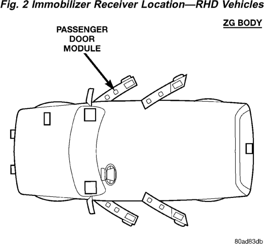
(2) Remove the left front door trim panel for RHD vehicles (Fig. 2) or the right front door trim panel for LHD vehicles (Fig. 3). Refer to Group 23—Body in this manual for trim panel removal procedure.
(3) Remove the receiver. (4) Unplug the immobilizer receiver from the wire harness connector.
(5) Reverse the removal procedures to install. (6) Refer to the Vehicle Theft Security System menu item on the DRB scan tool for the procedures
to program transmitter vehicle access codes into the memory of the new immobilizer receiver. Detailed diagnostic procedures can be found in the 1998 ZG Powertrain Diagnostic Manual.
HOOD SWITCH
(1) Disconnect and isolate the battery negative cable.
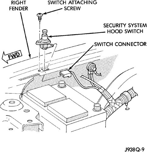
(2) Remove the screw securing the hood switch to the right inner fender ledge (Fig. 4).
(3) Unplug the wire connector from the switch. (4) Remove the switch from the mounting hole in the inner fender ledge.
(5) Reverse the removal procedures to install. Tighten the switch mounting screw to 1.5 N·m (15 in. lbs.).
DOOR AJAR SWITCH
(1) Disconnect and isolate the battery negative cable.
(2) Remove the screw that secures the door ajar switch to the pillar at the rear of the door opening (Fig. 5).
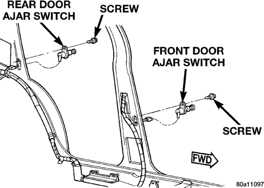
(3) Pull the switch out from the mounting hole in the door opening far enough to access the wire harness connector.
(4) Unplug the wire harness connector from the switch.
(5) Reverse the removal procedures to install. Tighten the switch mounting screw to 1.7 N·m (15 in. lbs.).
DOOR LOCK CYLINDER SWITCH
(1) Disconnect and isolate the battery negative cable.
(2) Remove the bezel near the inside door latch release handle by inserting a straight-bladed screwdriver in the notched end of the bezel and prying gently upwards.
(3) Remove the screw located beneath the bezel that secures the front door trim panel to the inner door panel (Fig. 6).
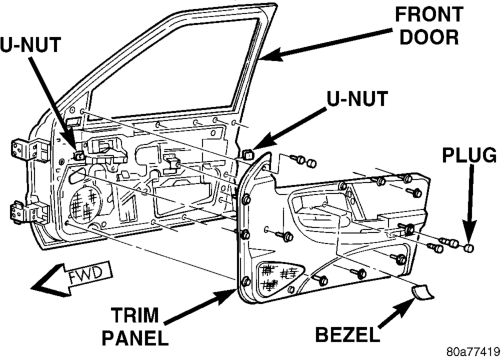
(4) Remove the trim cap and screw near the rear of the front door armrest.
(5) Remove the trim cap and screw at the upper front corner of the front door trim panel.
(6) Remove the screw located above the front door speaker grille on the front door trim panel.
(7) Using a trim stick or another suitable wide flat-bladed tool, gently pry the front door trim panel away from the door around the perimeter to release the trim panel retainers.
NOTE: To aid in the removal of the trim panel, start at the bottom of the panel.
(8) Pull the front door trim panel away from the inner door panel far enough to access and unplug the wire harness connectors from the door module and, if the vehicle is so equipped, from the front door courtesy lamp.
(9) Pull the watershield away from the rear access holes in the front door inner panel.
(10) Remove the U-clip retainer that secures the lock cylinder to the outer door panel (Fig. 7).
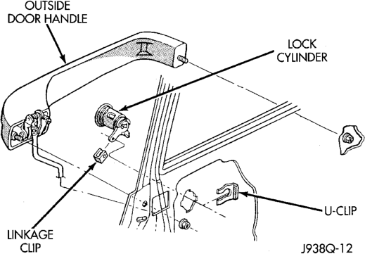
(11) Disconnect the door lock cylinder actuator rod from the door latch by unsnapping the plastic retainer.
(12) Pull the lock cylinder out of its mounting hole from the outside of the door panel far enough to pry the lock cylinder switch off of the back of the lock cylinder (Fig. 8).
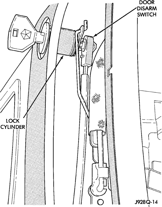
Typical
(13) From the inside of the door unplug the lock cylinder switch wire harness connector and remove the switch from the door.
(14) Reverse the removal procedures to install. Tighten the mounting screws to 2.2 N·m (20 in. lbs.).
LIFTGATE AJAR SWITCH
(1) Disconnect and isolate the battery negative cable.
(2) Open the liftgate. (3) Remove the screws that secure the liftgate lower trim panel to the liftgate inner panel (Fig. 9).
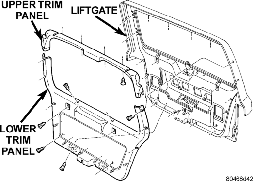
(4) Using a trim stick or another suitable wide flat-bladed tool, gently pry the perimeter edges of the trim panel away from the liftgate inner panel to release the retainers.
NOTE: To aid in the removal of the trim panel, start at the bottom of the panel.
(5)
Remove the liftgate trim panel from the vehicle.
(6) Remove the three screws that secure the liftgate latch to the liftgate (Fig. 10).
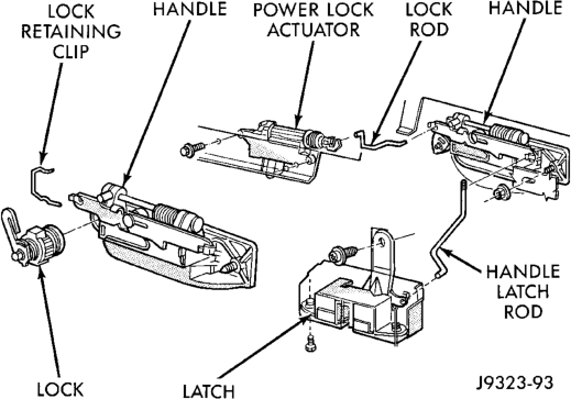
(7) Disconnect the liftgate handle latch actuator rod from the latch.
(8) Unplug the liftgate ajar switch wire harness connector from the latch.
(9) Remove the latch from the liftgate. (10) Reverse the removal procedures to install. Tighten the latch mounting screws to 7 N·m (62 in lbs.).
LIFTGATE LOCK CYLINDER SWITCH
(1) Disconnect and isolate the battery negative cable.
(2) Open the liftgate. (3) Remove the screws that secure the liftgate lower trim panel to the liftgate inner panel (Fig. 11).
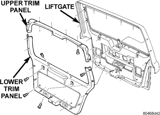
(4) Using a trim stick or another suitable wide flat-bladed tool, gently pry the perimeter edges of the trim panel away from the liftgate inner panel to release the retainers.
NOTE: To aid in the removal of the trim panel, start at the bottom of the panel.
(5) Remove the lower liftgate trim panel from the vehicle.
(6) Pry the liftgate lock cylinder switch off of the back of the lock cylinder (Fig. 12).
(7) Unplug the lock cylinder switch wire harness connector and remove the switch from inside the liftgate.
(8) Reverse the removal procedures to install. Tighten the mounting screws to 2.2 N·m (20 in. lbs.).
LIFTGLASS AJAR SWITCH
(1)
Disconnect and isolate the battery negative cable.
(2) Open the liftgate. (3) Remove the screws that secure the liftgate lower trim panel to the liftgate inner panel (Fig. 13).
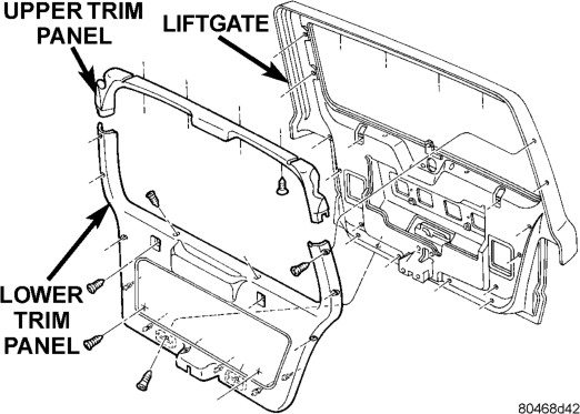
(4) Using a trim stick or another suitable wide flat-bladed tool, gently pry the perimeter edges of the trim panel away from the liftgate inner panel to release the retainers.
NOTE: To aid in the removal of the trim panel, start at the bottom of the panel.
(5) Remove the lower liftgate trim panel from the vehicle.
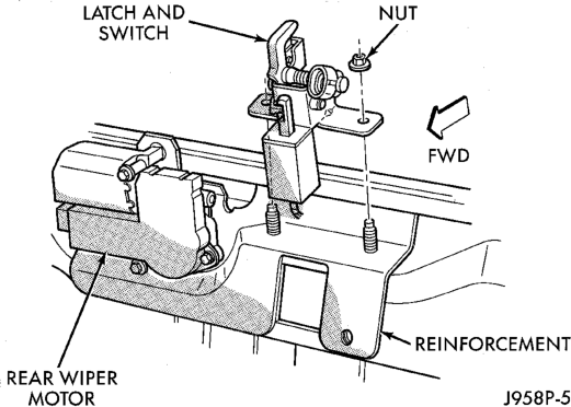
(6) Remove the two nuts that secure the liftglass latch to the liftgate inner panel (Fig. 14).
(7) Unplug the wire harness connectors for the liftglass latch solenoid and the liftglass ajar switch.
(8) Remove the liftglass latch from the liftgate. (9) Reverse the removal procedures to install. Tighten the latch mounting nuts to 11 N·m (100 in. lbs.). Tighten the trim panel mounting screws to 2.2 N·m (20 in. lbs.).
AUTO HEADLAMP AND PARK LAMP RELAYS
WARNING: ON VEHICLES EQUIPPED WITH AIR- BAGS, REFER TO GROUP 8M - PASSIVE RESTRAINT SYSTEMS BEFORE ATTEMPTING ANY STEERING WHEEL, STEERING COLUMN, OR INSTRUMENT PANEL COMPONENT DIAGNOSIS OR SERVICE. FAILURE TO TAKE THE PROPER PRE- CAUTIONS COULD RESULT IN ACCIDENTAL AIR- BAG DEPLOYMENT AND POSSIBLE PERSONAL INJURY.
(1) Disconnect and isolate the battery negative cable.
(2) Remove the fuse access panel by unsnapping it from the right cowl side trim panel.
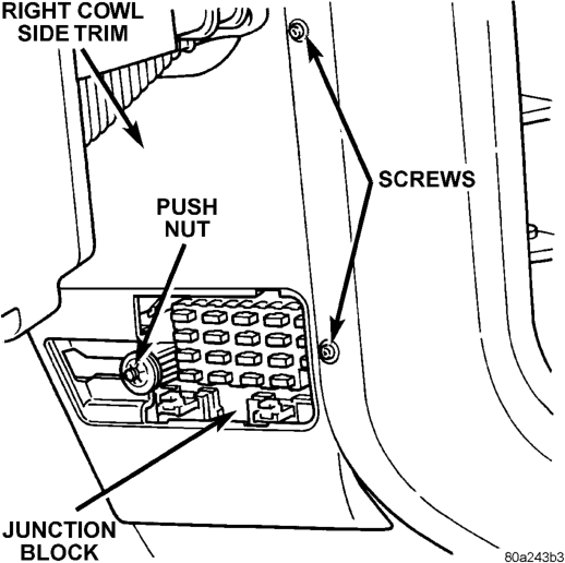
(3) Remove the push nut that secures the right cowl side trim panel to the junction block stud (Fig. 15).
(4) Remove the two screws that secure the right cowl side trim panel to the right front door opening trim.
(5) Remove the right cowl side trim panel from the right cowl side inner panel.
(6) Unplug the headlamp or park lamp relay from the junction block.
(7) Install the headlamp or park lamp relay by aligning the relay terminals with the cavities in the junction block and pushing the relay firmly into place.
(8) Connect the battery negative cable. (9) Test the relay operation. (10) Reinstall the right cowl side trim and the fuse access panel.
HORN RELAY
(1) Disconnect and isolate the battery negative cable.
(2) Remove the cover from the Power Distribution Center (PDC) (Fig. 16).
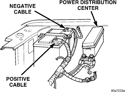
(3) Refer to the label on the PDC for horn relay identification and location. (4) Unplug the horn relay from the PDC. (5) Install the horn relay by aligning the relay terminals with the cavities in the PDC and pushing the relay firmly into place.
(6) Install the PDC cover. (7) Connect the battery negative cable. (8) Test the relay operation.
SET LAMP
WARNING: ON VEHICLES EQUIPPED WITH AIR- BAGS, REFER TO GROUP 8M - PASSIVE RESTRAINT SYSTEMS BEFORE ATTEMPTING ANY STEERING WHEEL, STEERING COLUMN, OR INSTRUMENT PANEL COMPONENT DIAGNOSIS OR SERVICE. FAILURE TO TAKE THE PROPER PRE- CAUTIONS COULD RESULT IN ACCIDENTAL AIR- BAG DEPLOYMENT AND POSSIBLE PERSONAL INJURY.
(1) Disconnect and isolate the battery negative cable.
(2) Using a trim stick or another suitable wide flat-bladed tool, gently pry the cowl top trim panel off of the instrument panel top pad (Fig. 17).
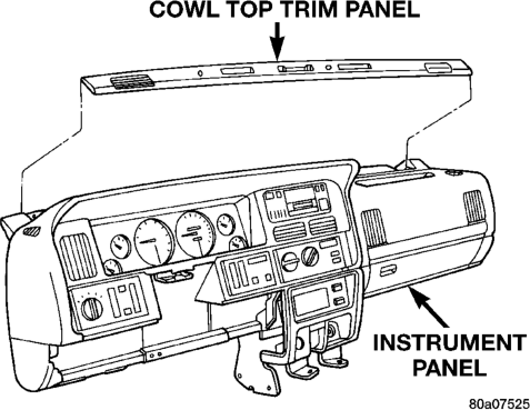
(3) Pull the trim panel up far enough to access and unplug the wire harness connector for the solar sensor, or to remove the solar sensor from the cowl top trim, if the vehicle is so equipped.
(4) Remove the cowl top trim panel from the instrument panel. (5) Remove the auto headlamp light sensor/vehicle theft security system set lamp mounting screw near the driver side defroster duct outlet.
(6) Pull the set lamp up from the top of the instrument panel far enough to access and unplug the wire harness connector.
(7) remove the set lamp from the instrument panel.
(8) Reverse the removal procedures to install. Tighten the mounting screw to 2.2 N·m (20 in. lbs.).