Suspension — 1998 Jeep Grand Cherokee ZJ Export Service Manual
Pages 29–61 · 32 pages · 3 words repaired
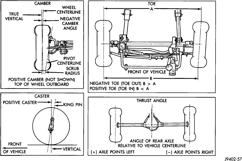
• STEERING AXIS INCLINATION ANGLE is measured in degrees and is the angle that the steering knuckles are tilted. The inclination angle has a fixed relationship with the camber angle. It will not change except when a spindle or ball stud is damaged or bent. The angle is not adjustable, damaged component(s) must be replaced to correct the steering axis inclination angle.
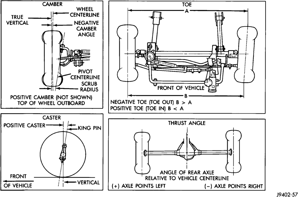
• THRUST ANGLE is the angle of the rear axle relative to the centerline of the vehicle. Incorrect thrust angle can cause off-center steering and excessive tire wear. This angle is not adjustable, damaged component(s) must be replaced to correct the thrust angle.
CAUTION: Never attempt to modify suspension or steering components by heating or bending.
NOTE: Periodic lubrication of the front suspension/ steering system components may be required. Rubber bushings must never be lubricated. Refer to Group 0, Lubrication And Maintenance for the recommended maintenance schedule.
DIAGNOSIS AND TESTING
SUSPENSION AND STEERING SYSTEM
FRONT END NOISE 1. Loose or worn wheel bearings. 1. Adjust or replace wheel bearings. 2. Loose or worn steering or suspension components.
EXCESSIVE PLAY IN STEERING 1. Loose or worn wheel bearings. 1. Adjust or replace wheel bearings. 2. Loose or worn steering or suspension components.
FRONT WHEELS SHIMMY 1. Loose or worn wheel bearings. 1. Adjust or replace wheel bearings. 2. Loose or worn steering or suspension components.
VEHICLE INSTABILITY 1. Loose or worn wheel bearings. 1. Adjust or replace wheel bearings. 2. Loose or worn steering or suspension components.
EXCESSIVE STEERING EFFORT 1. Loose or worn steering gear. 1. Adjust or replace steering gear. 2. Power steering fluid low. 2. Add fluid and repair leak. 3. Column coupler binding. 3. Replace coupler. 4. Tire pressure. 4. Adjust tire pressure. 5. Alignment. 5. Align vehicle to specifications.
VEHICLE PULLS TO ONE SIDE 1. Tire pressure. 1. Adjust tire pressure. 2. Alignment. 2. Align vehicle to specifications. 3. Loose or worn steering or suspension components.
SERVICE PROCEDURES
PRE-ALIGNMENT
Before starting wheel alignment, the following inspection and necessary corrections must be completed. Refer to Suspension and Steering System Diagnosis Chart for additional information.
(1) Inspect tires for size, air pressure and tread wear.
(2) Inspect front wheel bearings for wear. (3) Inspect front wheels for excessive radial or lateral runout and balance.
(4) Inspect ball studs, linkage pivot points and steering gear for looseness, roughness or binding.
(5) Inspect suspension components for wear and noise.
CONDITION POSSIBLE CAUSES CORRECTION
2. Tighten or replace components as necessary.
2. Tighten or replace components as necessary. 3. Loose or worn steering gear. 3. Adjust or replace steering gear.
2. Tighten or replace components as necessary. 3. Tires worn or out of balance. 3. Replace or balance tires. 4. Alignment. 4. Align vehicle to specifications. 5. Leaking steering dampener. 5. Replace steering dampener.
2. Tighten or replace components as necessary. 3. Tire pressure. 3. Adjust tire pressure. 4. Alignment. 4. Align vehicle to specifications.
3. Tighten or replace components as necessary. 4. Radial tire lead. 4. Rotate or replace tire as necessary. 5. Brake pull. 5. Repair brake as necessary. 6. Weak or broken spring. 6. Replace spring.
WHEEL ALIGNMENT
Before each alignment reading the vehicle should be jounced (rear first, then front). Grasp each bumper at the center and jounce the vehicle up and down three times. Always release the bumper in the down position.
To obtain an accurate alignment, a 4 wheel alignment machine must be used and the equipment calibration verified.
CAMBER
The wheel camber angle is preset. This angle is not adjustable and cannot be altered.
CASTER
Before checking the caster angle of the front axle, be sure the axle is not bent or twisted. Road test the vehicle and observe the steering wheels ability to return-to-center after left and right hand turns. A low or negative caster angle will cause the steering wheel poor return-to-center ability.
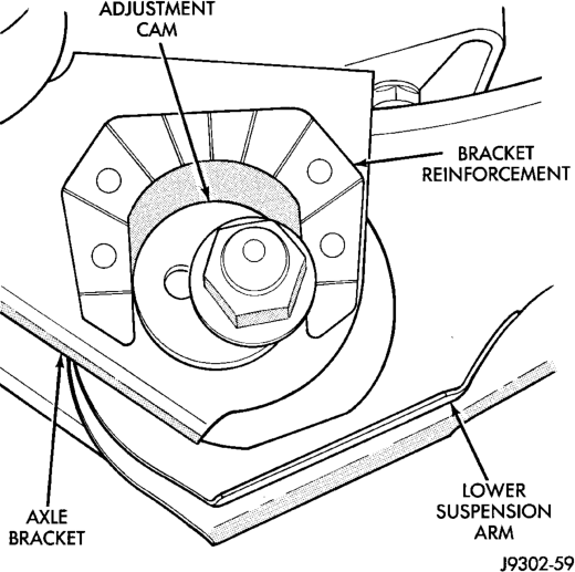
Caster is adjusted by loosening and rotating the cams on the lower suspension arm (Fig. 2).
NOTE: Changing caster angle will also change the front propeller shaft angle. The propeller shaft angle has priority over caster. Refer to Group 3, Differential and Driveline for additional information.
TOE POSITION
NOTE: The wheel toe position adjustment is the final adjustment. The adjustment must be performed with the engine running.
(1) Apply parking brakes. (2) Start the engine and turn wheels both ways before straightening the steering wheel. Center and secure the steering wheel.
(3) Loosen the adjustment sleeve clamp bolts (Fig. 3).
(4) Adjust the right wheel toe position with the drag link (Fig. 4) and (Fig. 5). Turn the sleeve until the right wheel is at the preferred positive TOE-IN specification. Position the clamp bolts as shown (Fig. 3) and tighten to 49 N·m (36 ft. lbs.).
NOTE: Tighten clamp bolt nearest the pitman arm first. Make sure the toe setting does not change during clamp tightening.
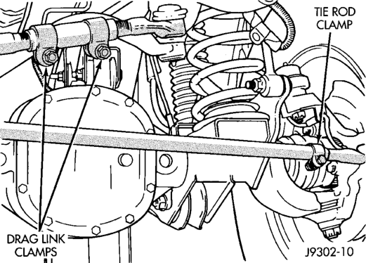
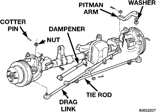
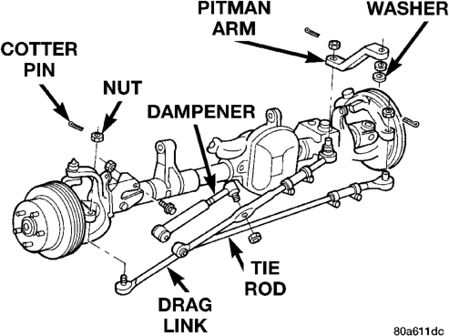
(5) Adjust the left wheel toe position with the tie rod. Turn the sleeve until the left wheel is at the preferred positive TOE-IN specification and the TOE DIFFERENTIAL is within .05°. Position the clamp bolts as shown (Fig. 3) and tighten to:
• Vehicles with 6 cyl engine: 27 N·m (20 ft. lbs.) • Vehicles with 8 cyl engine: 49 N·m (36 ft. lbs.)
NOTE: Tighten the clamp bolt furthest from the wheel first. Make sure the toe setting does not change during clamp tightening.
(6) Verify alignment specifications, then turn the engine off.
SPECIFICATIONS
ALIGNMENT
FRONT WHEELS
ADJUSTMENT PREFERRED RANGE
CASTER 7° 6.5° to 7.5°
CAMBER NA " 1.13° to +
0.13°
TOE-IN (each wheel)
0.12° 0° to + 0.22°
Toe Differential Left to Right .05°
REAR AXLE
ADJUSTMENT SPECIFICATION
THRUST ANGLE 6 .25°
TOTAL TOE-IN 0.00 to + 0.5°
DESCRIPTION AND OPERATION
FRONT SUSPENSION . . . . . . . . . . . . . . . . . . . . . 6 DIAGNOSIS AND TESTING
SHOCK DIAGNOSIS . . . . . . . . . . . . . . . . . . . . . . 7 REMOVAL AND INSTALLATION
AXLE BUSHING . . . . . . . . . . . . . . . . . . . . . . . . . . 9 COIL SPRING . . . . . . . . . . . . . . . . . . . . . . . . . . . 8 HUB BEARING . . . . . . . . . . . . . . . . . . . . . . . . . . 11 LOWER SUSPENSION ARM . . . . . . . . . . . . . . . . 8 SHOCK ABSORBER . . . . . . . . . . . . . . . . . . . . . . . 8
DESCRIPTION AND OPERATION
FRONT SUSPENSION
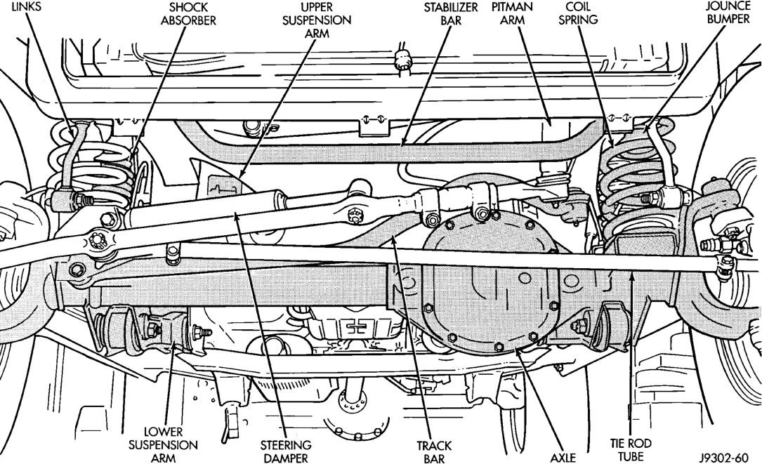
The Grand Cherokee front suspension is a link/coil design comprised of (Fig. 1):
• Drive axle (4WD), tube axle (2WD) • Dual-action shock absorbers • Coil springs • Upper and lower suspension arms
FRONT SUSPENSION
INDEX
page page
STABILIZER BAR . . . . . . . . . . . . . . . . . . . . . . . . 10 STEERING KNUCKLE . . . . . . . . . . . . . . . . . . . . . 8 TRACK BAR . . . . . . . . . . . . . . . . . . . . . . . . . . . . 11 UPPER SUSPENSION ARM . . . . . . . . . . . . . . . . . 9 WHEEL MOUNTING STUDS . . . . . . . . . . . . . . . . 12 SPECIFICATIONS
TORQUE CHART . . . . . . . . . . . . . . . . . . . . . . . . 12 SPECIAL TOOLS
FRONT SUSPENSION . . . . . . . . . . . . . . . . . . . . 13
• Stabilizer bar • Track bar • Jounce bumpers Link/Coil Suspension: The link/coil suspension allows each wheel to adapt to different road surfaces without greatly affecting the opposite wheel. Wheels are attached to a hub/bearings which bolts to the knuckles. The hub/bearing is not serviceable and is replaced as a unit. Steering knuckles pivot on replaceable ball studs attached to the axle tube yokes.
Shock Absorbers: The shock absorbers dampen jounce and rebound motion of the vehicle over various road conditions. The top of the shock absorbers are bolted to the body. The bottom of the shocks are bolted to the axle brackets.
Coil Springs: The coil springs control ride quality and maintain proper ride height. The coil springs mount up in the wheelhouse which is part of the unitized body bracket. A rubber doughnut isolator is located between the top of the spring and the body. The bottom of the spring seats on a axle pad and is retained with a clip.
Upper And Lower Suspension Arms: The suspension arms use bushings to isolate road noise. The suspension arms are bolted to the frame and axle through the rubber bushings. The lower suspension arm uses cam bolts at the axle to allow for caster and pinion angle adjustment. The suspension arm travel is limited through the use of jounce bumpers in compression and shocks absorbers in rebound. Stabilizer Bar: The stabilizer bar is used to control vehicle body roll during turns. The spring steel bar helps to control the vehicle body in relationship to the suspension. The bar extends across the front underside of the chassis and connects to the frame rails. Links are connected from the bar to the axle brackets. Stabilizer bar mounts are isolated by rubber bushings.
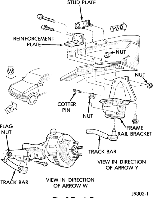
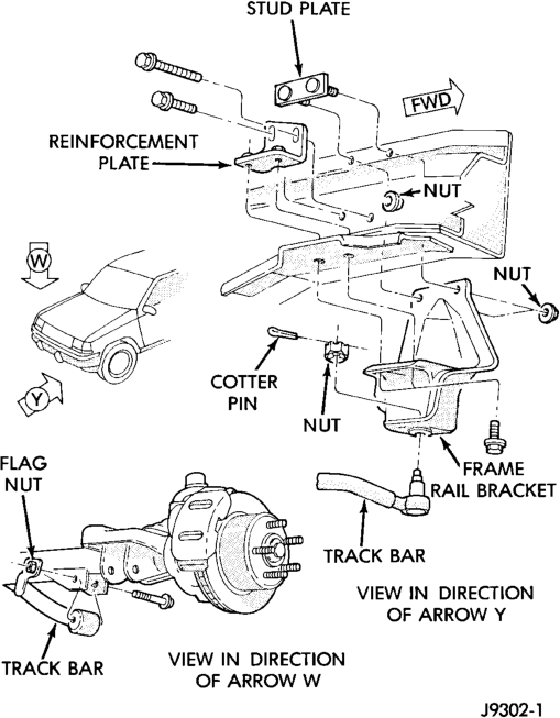
Track Bar: The track bar is used to control front axle lateral movement. The bar is attached to a frame rail bracket with a ball stud and isolated with a bushing at the axle bracket.
CAUTION: Components attached with a nut and cotter pin must be torqued to specification. Then if the slot in the nut does not line up with the cotter pin hole, tighten nut until it is aligned. Never loosen the nut to align the cotter pin hole.
CAUTION: Suspension components with rubber/ urethane bushings (except stabilizer bar) should be tightened with the vehicle at normal ride height. It is important to have the springs supporting the weight of the vehicle when the fasteners are torqued. If springs are not at their normal ride position, vehicle ride comfort could be affected and premature bushing wear may occur.
NOTE: Periodic lubrication of the front suspension/ steering system components may be required. Rubber bushings must never be lubricated. Refer to Group 0, Lubrication And Maintenance for the recommended maintenance schedule.
DIAGNOSIS AND TESTING
SHOCK DIAGNOSIS
A knocking or rattling noise from a shock absorber may be caused by movement between mounting bushings and metal brackets or attaching components. These noises can usually be stopped by tightening the attaching nuts. If the noise persists, inspect for damaged and worn bushings, and attaching components. Repair as necessary if any of these conditions exist.
A squeaking noise from the shock absorber may be caused by the hydraulic valving and may be intermittent. This condition is not repairable and the shock absorber must be replaced.
The shock absorbers are not refillable or adjustable. If a malfunction occurs, the shock absorber must be replaced. To test a shock absorber, hold it in an upright position and force the piston in and out of the cylinder four or five times. The action throughout each stroke should be smooth and even.
The shock absorber bushings do not require any type of lubrication. Do not attempt to stop bushing noise by lubricating them. Grease and mineral oilbase lubricants will deteriorate the bushing.
REMOVAL AND INSTALLATION
SHOCK ABSORBER
REMOVAL
(1) Remove the nut, retainer and grommet from the upper stud in the engine compartment (Fig. 2).
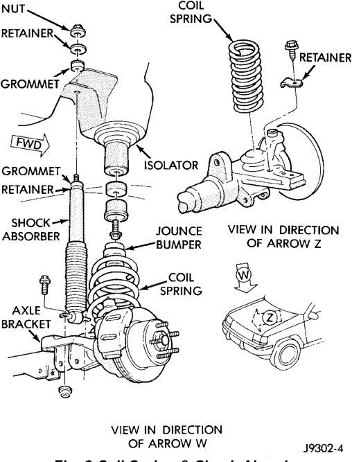
(2) Remove the lower nuts and bolts from the axle bracket. Remove the shock absorber.
INSTALLATION
(1) Position the lower retainer and grommet on the upper stud. Insert the shock absorber through the shock tower hole.
(2) Install the lower bolts and nuts. Tighten nuts to 28 N·m (250 in. lbs.).
(3) Install the upper grommet and retainer on the stud in the engine compartment. Install the nut and tighten to 23 N·m (17 ft. lbs.).
COIL SPRING
REMOVAL
(1) Raise and support the vehicle. Position a hydraulic jack under the axle to support it.
(2) Remove rear lower suspension arm bolts. (3) Remove caliper flex hose brackets from the frame rails.
(4) Remove ABS sensor wires from brackets. (5) Disconnect the stabilizer bar link and shock absorber from the axle.
(6) Disconnect the track bar from the frame rail bracket.
(7) Disconnect the drag link from the pitman arm. (8) Lower the axle until the spring is free from the upper mount. Remove the coil spring retainer bolt (Fig. 2) and remove the spring.
(9) Remove the jounce bumper if necessary from the upper spring mount (Fig. 2).
INSTALLATION
(1) Install the jounce bumper on the upper spring mount.
(2) Position the coil spring on the axle pad. Install the spring retainer and bolt.
(3) Raise the axle into position until the spring seats in the upper mount.
(4) Install lower suspension arms and rear bolts. (5) Install caliper flex hose brackets to the frame rails.
(6) Install ABS sensor wires into brackets. (7) Connect the stabilizer bar links and shock absorbers to the axle bracket. Connect the track bar to the frame rail bracket.
(8) Install drag link to pitman arm. (9) Remove the supports and lower the vehicle. (10) Tighten all suspension components to proper torque.
STEERING KNUCKLE
For service procedures on the steering knuckle and ball joints refer to Group 3 Differentials And Driveline.
LOWER SUSPENSION ARM
REMOVAL
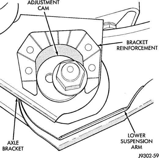
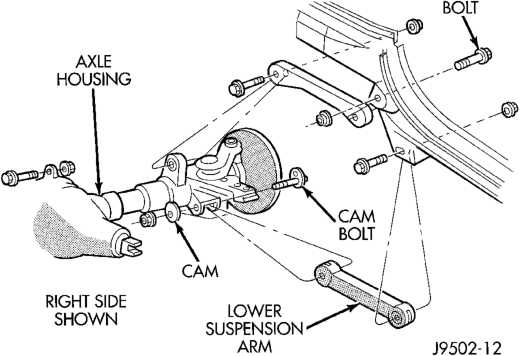
(1) Raise and support the vehicle. (2) Paint or scribe alignment marks on the cam adjusters and suspension arm for installation reference (Fig. 3).
(3) Remove the lower suspension arm nut, cam and cam bolt from the axle (Fig. 4).
(4) Remove the nut and bolt from the frame rail bracket and remove the lower suspension arm (Fig. 4).
INSTALLATION
(1) Position the lower suspension arm at the axle bracket and frame rail bracket.
(2) Install the rear bolts and finger tighten the new nuts.
(3) Install a new cam bolt, cam and new nut in the axle. Re-align the reference marks.
(4) Install the bolts and finger tighten the new nuts.
(5) Lower the vehicle. (6) Tighten the axle bracket nut to 115 N·m (85 ft. lbs.).
(7) Tighten the frame bracket nut to 176 N·m (130 ft. lbs.).
(8) Check the alignment if new parts were installed.
UPPER SUSPENSION ARM
REMOVAL
(1) Raise and support the vehicle. (2) Remove the upper suspension arm nut and bolt at the axle bracket (Fig. 4).
(3) Remove the nut and bolt at the frame rail and remove the upper suspension arm.
INSTALLATION
(1) Position the upper suspension arm at the axle and frame rail.
(2) Install the bolts and finger tighten the nuts. (3) Remove the supports and lower the vehicle. (4) Tighten the nut at the axle and frame bracket to 75 N·m (55 ft. lbs.).
AXLE BUSHING
REMOVAL
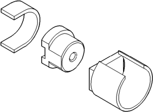
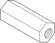
(1) Remove the upper suspension arm from axle. (2) Position spacer 7932-1 (J-35581-1) over the bushing in the axle for two-wheel drive axles and right side on Model 30 axle.
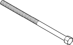
(3) Install Bushing Removal/Installer (Fig. 5). (4) Remove the bushing by tightening the Long Nut.
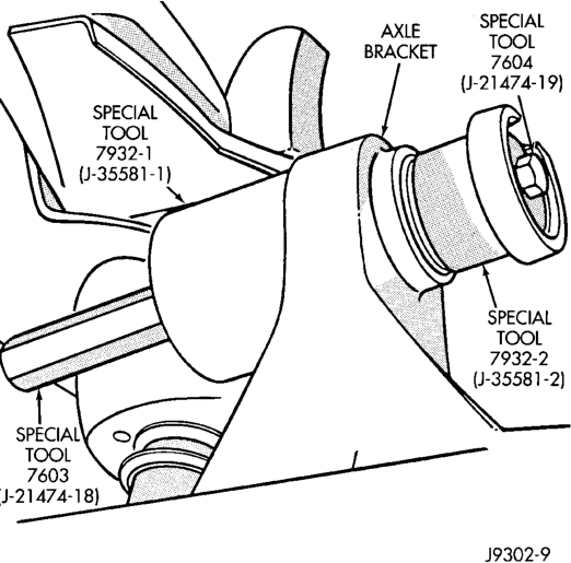
NOTE: For two-wheel drive axles and right side on Model 30 axle, do not remove spacer 7932-1 (J-35581-1). This spacer is need for installation.
INSTALLATION
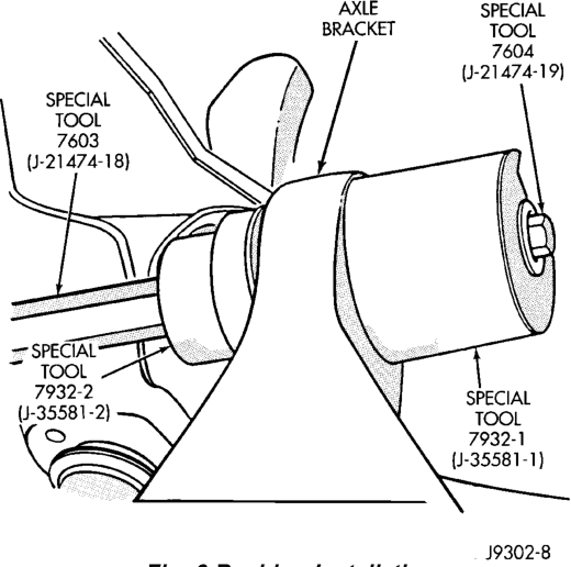
(1) Position new bushing, Receiver and Installer on axle (Fig. 6).
(2) Install the bushing by tightening the Long Nut.
(3)
Remove tools and install the upper suspension arm.
STABILIZER BAR
REMOVAL
(1) Raise and support the vehicle. (2)
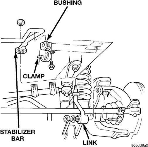
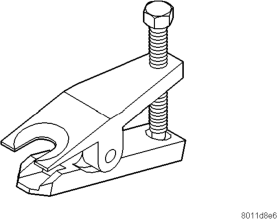
Remove upper link nuts (Fig. 7) and separate links from the stabilizer bar with Remover MB-990635.
(3) Remove the stabilizer bar clamps bolts from the frame rails and remove the stabilizer bar.
(4) Remove the stabilizer bar link nuts from the axle brackets (Fig. 7).
INSTALLATION
(1) Position the stabilizer bar on the frame rail and install the clamps and bolts. Ensure the bar is centered with equal spacing on both sides. Tighten the bolts to 54 N·m (40 ft. lbs.).
(2) Install the links into the stabilizer bar and axle brackets.
(3) Tighten the nuts at the axle bracket end to 95 N·m (70 ft. lbs.).
(4) Tighten the stabilizer bar to link nuts to 61 N·m (45 ft. lbs.).
(5) Remove the supports and lower the vehicle. (6) Tighten the nuts at the axle bracket end to 95 N·m (70 ft. lbs.).
TRACK BAR
REMOVAL
(1) Raise and support the vehicle. (2) Remove the cotter pin and nut from the ball stud end at the frame rail bracket (Fig. 8).
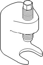
(3) Use a universal puller to separate the ball stud from the frame rail bracket.
(4) Remove the bolt and flag nut from the axle shaft tube bracket (Fig. 8). Remove the track bar.
INSTALLATION
(1) Install the track bar at axle tube bracket. Loosely install the retaining bolt and flag nut.
(2) It may be necessary to pry the axle assembly over to install the track bar at the frame rail. Install track bar at the frame rail bracket. Install the retaining nut on the stud.
(3) Tighten the ball stud nut to 81 N·m (60 ft. lbs.). Install a new cotter pin.
(4) Remove the supports and lower the vehicle. (5) Tighten the bolt at the axle shaft tube bracket to 75 N·m (55 ft. lbs.).
(6)
Check alignment if a new track bar was installed.
HUB BEARING
REMOVAL
(1) Raise and support the vehicle. (2) Remove the wheel and tire assembly. (3) Remove the brake caliper, rotor and ABS wheel speed sensor, refer to Group 5 Brakes.
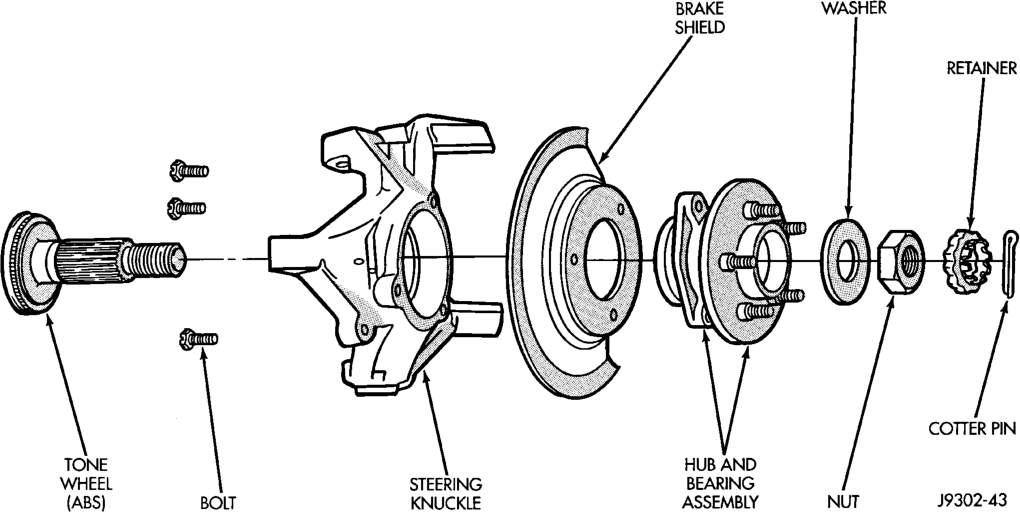
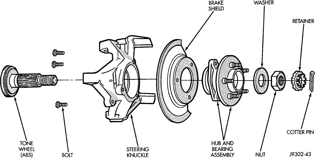
(4) Remove the cotter pin, nut retainer and axle hub nut (Fig. 9).
(5) Remove the hub mounting bolts and remove hub bearing from the steering knuckle and axle shaft.
INSTALLATION
(1) Install the hub bearing and brake dust shield to the knuckle.
(2) Install the hub to knuckle bolts and tighten to 102 N·m (75 ft. lbs.).
(3) Install the hub washer and nut. Tighten the hub nut to 237 N·m (175 ft. lbs.). Install the nut retainer and a new cotter pin.
(4) Install the brake rotor, caliper and ABS wheel speed sensor, refer to Group 5 Brakes.
(5) Install the wheel and tire assembly. (6) Remove support and lower the vehicle.
WHEEL MOUNTING STUDS
REMOVAL
(1) Raise and support vehicle. (2) Remove wheel and tire assembly. (3) Remove brake caliper and rotor, refer to Group 5 Brakes for procedure.
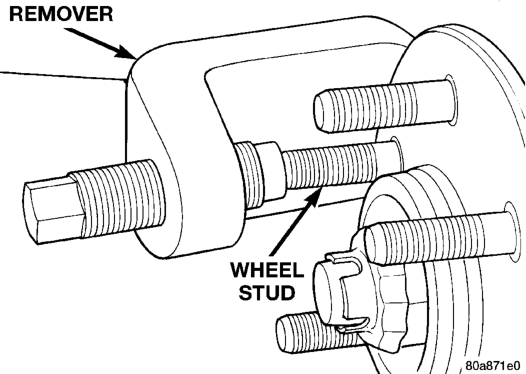
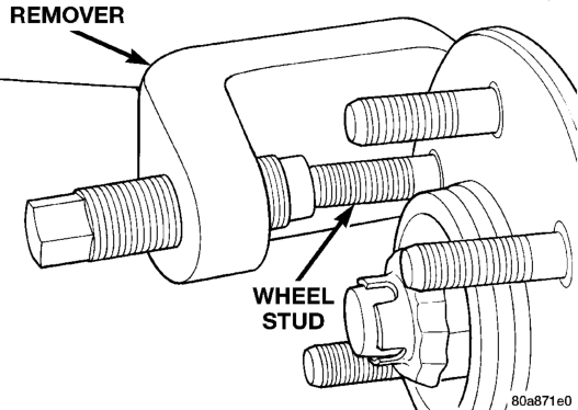
(4) Remove stud from hub with Remover C-4150A (Fig. 10).
INSTALLATION
(1) Install new stud into hub flange. (2) Install three washers onto stud, then install lug nut with the flat side of the nut against the washers.
(3) Tighten lug nut until the stud is pulled into the hub flange. Verify that the stud is properly seated into the flange.
(4) Remove lug nut and washers. (5) Install the brake rotor and caliper, refer to Group 5 Brakes for procedure.
(6) Install wheel and tire assembly, use new lug nut on stud or studs that were replaced.
(7) Remove support and lower vehicle.
SPECIFICATIONS
TORQUE CHART
DESCRIPTION TORQUE Shock Absorber
Upper Nut. . . . . . . . . . . . . . . . .23 N·m (17 ft. lbs.) Lower Nut. . . . . . . . . . . . . . . .28 N·m (250 in. lbs.) Suspension Arm Upper
Nuts . . . . . . . . . . . . . . . . . . . . .75 N·m (55 ft. lbs.) Suspension Arm Lower
Axle Bracket Nut. . . . . . . . . . .115 N·m (85 ft. lbs.) Frame Bracket Nut . . . . . . . .176 N·m (130 ft. lbs.) Stabilizer Bar
Clamp Bolt . . . . . . . . . . . . . . . .54 N·m (40 ft. lbs.) Link Upper Nut. . . . . . . . . . . . .61 N·m (45 ft. lbs.) Link Lower Bolt . . . . . . . . . . . .95 N·m (70 ft. lbs.) Track Bar
Ball Stud Nut . . . . . . . . . . . . . .81 N·m (60 ft. lbs.) Axle Bracket Bolt . . . . . . . . . . .75 N·m (55 ft. lbs.) Track Bar Bracket
Bolts . . . . . . . . . . . . . . . . . . . .121 N·m (90 ft. lbs.) Nut . . . . . . . . . . . . . . . . . . . . .121 N·m (90 ft. lbs.) Support Bolts . . . . . . . . . . . . . .95 N·m (70 ft. lbs.) Hub Bearing Bolts . . . . . . . . . . . . . . . . . . . . . .102 N·m (75 ft. lbs.)
SPECIAL TOOLS
FRONT SUSPENSION






DESCRIPTION AND OPERATION
REAR SUSPENSION . . . . . . . . . . . . . . . . . . . . . 14 DIAGNOSIS AND TESTING
SHOCK DIAGNOSIS . . . . . . . . . . . . . . . . . . . . . . 15 REMOVAL AND INSTALLATION
COIL SPRING . . . . . . . . . . . . . . . . . . . . . . . . . . . 15 LOWER SUSPENSION ARM . . . . . . . . . . . . . . . . 16
DESCRIPTION AND OPERATION
REAR SUSPENSION
The rear suspension is link/coil design comprised of (Fig. 1):
• Drive axle • Dual-action shock absorbers • Coil springs • Upper and lower suspension arms • Track bar • Stabilizer bar Upper And Lower Suspension: The suspension arms use bushings to isolate road noise. The suspension arms are bolted to the body and axle through the rubber bushings. The lower suspension arm has provision for the use of cam bolts at the axle to allow for pinion angle or thrust angle adjustment. The cams are available as a service kit and are not installed at the factory. The suspension arm travel is limited through the of use jounce bumpers in compression and shock absorbers in rebound.
Shock Absorbers: The shock absorbers dampen jounce and rebound of the vehicle over various road conditions. The top of the shock absorbers are bolted to the body. The bottom of the shocks are bolted to the axle shock absorber bracket.
Coil Springs: The coil springs mount up in the fender shield that is part of the unitized body bracket. There is a rubber isolator between the top of the spring and bracket to isolate road noise. The bottom of the spring seats on the axle pad and is retained with a clip.
Stabilizer Bar: The stabilizer bar is used to control vehicle body roll during turns. The spring steel bar helps to equalize the vehicle body in relationship to the suspension. The bar extends across the underside of the chassis and connects to the frame rails. Links are connected from the bar to the axle brackets. Stabilizer bar are isolated by rubber bushings.
REAR SUSPENSION
INDEX
page page
SHOCK ABSORBER . . . . . . . . . . . . . . . . . . . . . . 15 STABILIZER BAR . . . . . . . . . . . . . . . . . . . . . . . . 16 TRACK BAR . . . . . . . . . . . . . . . . . . . . . . . . . . . . 17 UPPER SUSPENSION ARM . . . . . . . . . . . . . . . . 16 SPECIFICATIONS
TORQUE CHART . . . . . . . . . . . . . . . . . . . . . . . . 17
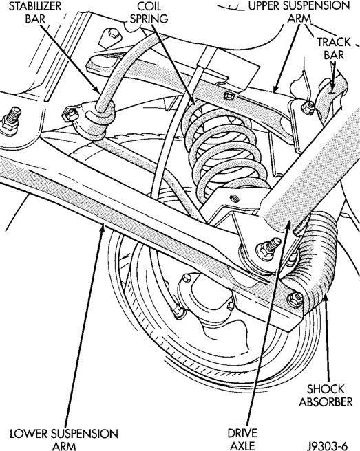
Track Bar: The track bar is used to control rear axle lateral movement. The track bar is attached to a frame rail bracket and an axle bracket. It is isolated with bushings at both ends.
CAUTION: Suspension components with rubber/ urethane bushings (except stabilizer bar) should be tightened with the vehicle at normal ride height. It is important to have the springs supporting the weight of the vehicle when the fasteners are torqued. This will maintain vehicle ride comfort and prevent premature bushing wear.
DIAGNOSIS AND TESTING
SHOCK DIAGNOSIS
A knocking or rattling noise from a shock absorber may be caused by movement between mounting bushings and metal brackets or attaching components. These noises can usually be stopped by tightening the attaching nuts. If the noise persists, inspect for damaged and worn bushings, and attaching components. Repair as necessary if any of these conditions exist.
A squeaking noise from the shock absorber may be caused by the hydraulic valving and may be intermittent. This condition is not repairable and the shock absorber must be replaced.
The shock absorbers are not refillable or adjustable. If a malfunction occurs, the shock absorber must be replaced. To test a shock absorber, hold it in an upright position and force the piston in and out of the cylinder four or five times. The action throughout each stroke should be smooth and even.
The shock absorber bushings do not require any type of lubrication. Do not attempt to stop bushing noise by lubricating them. Grease and mineral oilbase lubricants will deteriorate the bushing.
REMOVAL AND INSTALLATION
SHOCK ABSORBER
REMOVAL
(1) Raise and support the vehicle. Position a hydraulic jack under the axle to support it.
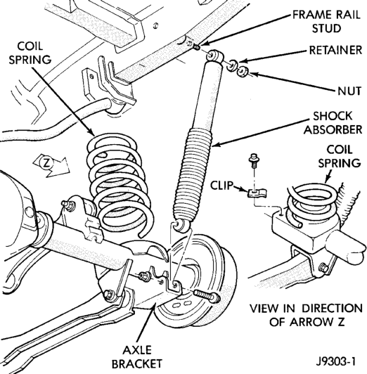
(2) Remove the upper nut and retainer from the frame rail stud (Fig. 2).
(3) Remove the lower nut and bolt from the axle bracket. Remove the shock absorber.
INSTALLATION
(1) Install the shock absorber on the upper frame rail stud. Install the shock absorber on the axle bracket.
(2) Install the retainer and nut on the stud. Tighten the upper nut to 70 N·m (52 ft. lbs.).
(3) Install lower bolt and nut finger tight. (4) Remove the supports and lower the vehicle. (5) Tighten the lower nut to 92 N·m (68 ft. lbs.).
COIL SPRING
REMOVAL
(1) Raise and support the vehicle. Position a hydraulic jack under the axle to support it.
(2) Disconnect the stabilizer bar link and shock absorber from the axle bracket.
(3) Disconnect the track bar from the frame rail bracket.
(4) Lower the axle until the spring is free from the upper mount seat. Remove the coil spring retainer bolt (Fig. 2) and remove the spring.
INSTALLATION
Inspect isolator for damage or wear. Replace the isolator if necessary before installing spring. (1) Position the coil spring on the axle pad. Install the spring retainer and bolt. Tighten the bolt to 22 N·m (16 ft. lbs.).
(2) Raise the axle into position until the spring seats in the upper mount.
(3) Connect the stabilizer bar links and shock absorbers to the axle bracket. Connect the track bar to the frame rail bracket.
(4) Remove the supports and lower the vehicle. (5) Tighten the track bar and shock absorber to specified torque.
LOWER SUSPENSION ARM
REMOVAL
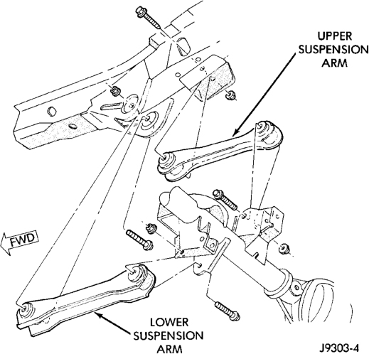
(1) Raise and support the vehicle. (2) Remove the lower suspension arm nut and bolt at the axle bracket (Fig. 3).
(3) Remove the nut and bolt (Fig. 3) at the frame rail and remove the lower suspension arm.
INSTALLATION
(1) Position the lower suspension arm at the axle bracket and frame rail bracket.
(2) Install the bolts and finger tighten the nuts. (3) Remove the supports and lower the vehicle. (4) Tighten the lower suspension arm nuts to 177 N·m (130 ft. lbs.).
UPPER SUSPENSION ARM
REMOVAL
(1) Raise and support the vehicle. (2) Remove the upper suspension arm nut and bolt at the axle bracket (Fig. 3). Remove the ABS wire bracket from the arm.
(3) Remove the nut and bolt at the frame rail and remove the upper suspension arm.
INSTALLATION
(1) Position the upper suspension arm at the axle and frame rail.
(2) Install the bolts and finger tighten the nuts. Install the ABS wire bracket onto the arm.
(3) Remove the supports and lower the vehicle. (4) Tighten the upper suspension arm nuts to 75 N·m (55 ft. lbs.).
STABILIZER BAR
REMOVAL
(1) Raise and support the vehicle. Remove one wheel and tire.
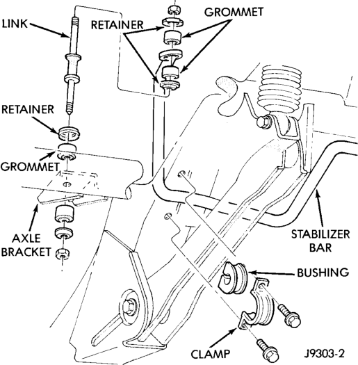
(2) Disconnect the stabilizer bar links from the axle brackets (Fig. 4).
(3) Lower the exhaust by disconnecting the muffler and tail pipe hangers.
(4) Disconnect the stabilizer bar from the links. (5) Disconnect the stabilizer bar clamps from the frame rails. Remove the stabilizer bar.
INSTALLATION
(1) Position the stabilizer bar on the frame rail and install the clamps and bolts. Ensure the bar is centered with equal spacing on both sides. Tighten the bolts to 54 N·m (40 ft. lbs.).
(2) Install the links and grommets onto the stabilizer bar and axle brackets. Install the nuts and tighten to 36 N·m (27 ft. lbs.).
(3) Connect the muffler and tail pipe to their hangers.
(4) Install the wheel and tire assembly.
TRACK BAR
REMOVAL
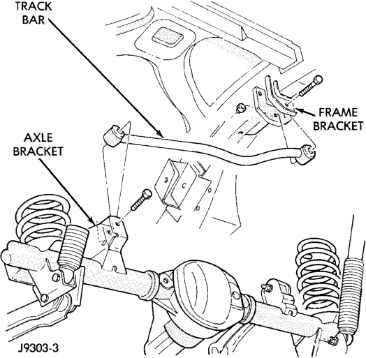
(1) Raise and support the vehicle. (2) Remove the bolt and nut from the frame rail bracket (Fig. 5).
(3) Remove the bolt from the axle tube bracket (Fig. 5). Remove the track bar.
INSTALLATION
(1) Install the track bar to the axle bracket and install a new bolt. (2) It may be necessary to pry the axle assembly over to install the track bar. Install the track bar to the frame rail bracket. Loosely install the bolt and flag nut.
(3) Remove the supports and lower the vehicle. (4) Tighten the track bar bolts 100 N·m (74 ft. lbs.).
SPECIFICATIONS
TORQUE CHART
DESCRIPTION TORQUE Shock Absorber
Upper Nut. . . . . . . . . . . . . . . . .70 N·m (52 ft. lbs.) Lower Nut . . . . . . . . . . . . . . . . .92 N·m (68 ft. lbs.) Suspension Arm Upper
Nuts . . . . . . . . . . . . . . . . . . . . .75 N·m (55 ft. lbs.) Suspension Arm Lower
Nuts. . . . . . . . . . . . . . . . . . . .177 N·m (130 ft. lbs.) Stabilizer Bar
Clamp Bolt . . . . . . . . . . . . . . . .54 N·m (40 ft. lbs.) Link Nut . . . . . . . . . . . . . . . . . .36 N·m (27 ft. lbs.) Track Bar
Frame Bracket Nut . . . . . . . . .100 N·m (74 ft. lbs.) Axle Bracket Bolt . . . . . . . . . .100 N·m (74 ft. lbs.)
SERVICE PROCEDURES
PRE-ALIGNMENT
Before starting wheel alignment, the following inspection and necessary corrections must be completed. Refer to Suspension and Steering System Diagnosis Chart for additional information.
(1) Inspect tires for size, air pressure and tread wear.
(2) Inspect front wheel bearings for wear. (3) Inspect front wheels for excessive radial or lateral runout and balance.
(4) Inspect ball studs, linkage pivot points and steering gear for looseness, roughness or binding.
(5) Inspect suspension components for wear and noise.
WHEEL ALIGNMENT
Before each alignment reading the vehicle should be jounced (rear first, then front). Grasp each bumper at the center and jounce the vehicle up and down three times. Always release the bumper in the down position.
CAMBER
The wheel camber angle is preset. This angle is not adjustable and cannot be altered.
CASTER
Check the caster of the front axle for correct angle. Be sure the axle is not bent or twisted. Road test the vehicle and observe the steering wheel return-to-center position. Low caster will cause poor steering wheel returnability.
During the road test, turn the vehicle to both the left and right. If the steering wheel returns to the center position unassisted, the caster angle is correct. However, if steering wheel does not return toward the center position unassisted, a low caster angle is probable.
Caster can be adjusted by loosening and rotating the cams on the lower suspension arm (Fig. 2). Changing caster angle will also change the front propeller shaft angle. The propeller shaft angle has priority over caster. Refer to Group 3, Differential and Driveline for additional information.
TOE POSITION (LHD)
NOTE: The wheel toe position adjustment should be the final adjustment.
(1) Start the engine and turn wheels both ways before straightening the steering wheel. Center and secure the steering wheel.
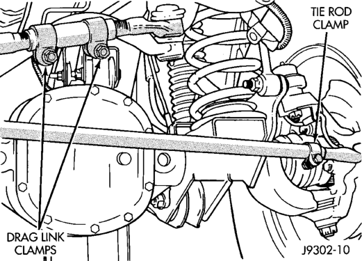
(2) Loosen the adjustment sleeve clamp bolts (Fig. 3).
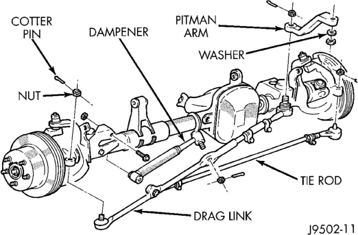
(3) Adjust the right wheel toe position with the drag link (Fig. 4). Turn the sleeve until the right wheel is at the correct positive TOE-IN position. Position the clamp bolts as shown (Fig. 3) and tighten to:
• Vehicles with 2.5L engine: 27 N·m (20 ft. lbs.) • Vehicles with 4.0L engine: 27 N·m (20 ft. lbs.) • Vehicles with 5.2L engine: 49 N·m (36 ft. lbs.)
NOTE: Make sure the toe setting does not change during clamp tightening.
(4) Adjust the left wheel toe position with the tie rod. Turn the sleeve until the left wheel is at the same TOE-IN position as the right wheel. Position the clamp bolts as shown (Fig. 3) and tighten to:
• Vehicles with 2.5L engine: 27 N·m (20 ft. lbs.) • Vehicles with 4.0L engine: 27 N·m (20 ft. lbs.) • Vehicles with 5.2L engine: 49 N·m (36 ft. lbs.)
NOTE: Make sure the toe setting does not change during clamp tightening.
(5) Verify the toe setting.
TOE POSITION (RHD)
NOTE: The wheel toe position adjustment should be the final adjustment.
(1) Start the engine and turn wheels both ways before straightening the steering wheel. Center and secure the steering wheel.
(2) Loosen the adjustment sleeve clamp bolts (Fig. 5).
(3) Adjust the left wheel toe position with the drag link (Fig. 5). Turn the sleeve until the left wheel is at the correct positive TOE-IN position. Position the clamp bolts to their original position and tighten to:
• Vehicles with 2.5L engine: 27 N·m (20 ft. lbs.) • Vehicles with 4.0L engine: 27 N·m (20 ft. lbs.) • Vehicles with 5.2L engine: 49 N·m (36 ft. lbs.)
NOTE: Make sure the toe setting does not change during clamp tightening.
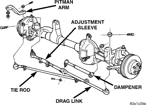
(4) Adjust the right wheel toe position with the tie rod. Turn the sleeve until the right wheel is at the same TOE-IN position as the left wheel. Position the clamp bolt to it's original position and tighten to:
• Vehicles with 2.5L engine: 27 N·m (20 ft. lbs.) • Vehicles with 4.0L engine: 27 N·m (20 ft. lbs.) • Vehicles with 5.2L engine: 49 N·m (36 ft. lbs.)
NOTE: Make sure the toe setting does not change during clamp tightening.
(5) Verify the toe setting.
SPECIFICATIONS
ALIGNMENT
FRONT WHEELS
ADJUSTMENT PREFERRED RANGE
CASTER 7° 6.5° to 7.5°
CAMBER NA " 1.13° to +
0.13°
TOE-IN (each wheel)
0.12° 0° to + 0.22°
Toe Differential Left to Right .05°
REAR AXLE
ADJUSTMENT SPECIFICATION
THRUST ANGLE 6 .25°
TOTAL TOE-IN 0.00 to + 0.5°
DESCRIPTION AND OPERATION
FRONT SUSPENSION . . . . . . . . . . . . . . . . . . . . . 5 DIAGNOSIS AND TESTING
SHOCK DIAGNOSIS . . . . . . . . . . . . . . . . . . . . . . 6 REMOVAL AND INSTALLATION
AXLE BUSHING . . . . . . . . . . . . . . . . . . . . . . . . . . 8 COIL SPRING . . . . . . . . . . . . . . . . . . . . . . . . . . . 7 HUB BEARING . . . . . . . . . . . . . . . . . . . . . . . . . . 10 LOWER SUSPENSION ARM . . . . . . . . . . . . . . . . 7 SHOCK ABSORBER . . . . . . . . . . . . . . . . . . . . . . . 6
DESCRIPTION AND OPERATION
FRONT SUSPENSION
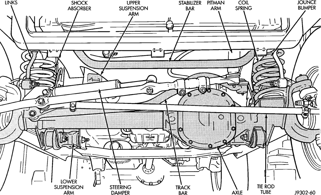
The front suspension is a link/coil design (Fig. 1). This design is used on Left Hand Drive (LHD) and Right Hand Drive (RHD) vehicles. The suspension is comprised of:
• Drive axle (4WD), tube axle (2WD) • Dual-action shock absorbers • Coil springs • Upper and lower suspension arms • Stabilizer bar • Track bar • Jounce Bumper Link/Coil Suspension: The link/coil suspension allows each wheel to adapt to different road surfaces without greatly affecting the opposite wheel. Wheels are attached to a hub/bearings which bolts to the knuckles. The hub/bearing is not serviceable and is replaced as a unit. Steering knuckles pivot on replaceable ball studs attached to the axle tube yokes.
Shock Absorbers: The shock absorbers dampen jounce and rebound motion of the vehicle over various road conditions. The top of the shock absorbers are bolted to the body. The bottom of the shocks are bolted to the axle brackets.
Coil Springs: The coil springs control ride quality and maintain proper ride height. The coil springs mount up in the wheelhouse which is part of the unitized body bracket. A rubber doughnut isolator is located between the top of the spring and the body. The bottom of the spring seats on a axle pad and is retained with a clip.
Upper And Lower Suspension: The suspension arms use bushings to isolate road noise. The suspension arms are bolted to the frame and axle through the rubber bushings. The lower suspension arm uses
FRONT SUSPENSION
INDEX
page page
STABILIZER BAR . . . . . . . . . . . . . . . . . . . . . . . . . 8 STEERING KNUCKLE . . . . . . . . . . . . . . . . . . . . . 7 TRACK BAR . . . . . . . . . . . . . . . . . . . . . . . . . . . . . 9 UPPER SUSPENSION ARM . . . . . . . . . . . . . . . . . 8 WHEEL MOUNTING STUDS . . . . . . . . . . . . . . . . 10 SPECIFICATIONS
TORQUE CHART . . . . . . . . . . . . . . . . . . . . . . . . 11 SPECIAL TOOLS
FRONT SUSPENSION . . . . . . . . . . . . . . . . . . . . 11 cam bolts at the axle to allow for caster and pinion angle adjustment. The suspension arm travel is limited through the use of jounce bumpers in compression and shocks absorbers in rebound.
Stabilizer Bar: The stabilizer bar is used to control vehicle body roll during turns. The spring steel bar helps to control the vehicle body in relationship to the suspension. The bar extends across the front underside of the chassis and connects to the frame rails. Links are connected from the bar to the axle brackets. Stabilizer bar mounts are isolated by rubber bushings.
Track Bar: The track bar is used to control front axle lateral movement. The bar is attached to a frame rail bracket with a ball stud and isolated with a bushing at the axle bracket.
CAUTION: Components attached with a nut and cotter pin must be torqued to specification. Then if the slot in the nut does not line up with the cotter pin hole, tighten nut until it is aligned. Never loosen the nut to align the cotter pin hole.
CAUTION: Suspension components with rubber/ urethane bushings (except stabilizer bar) should be tightened with the vehicle at normal ride height. It is important to have the springs supporting the weight of the vehicle when the fasteners are torqued. If springs are not at their normal ride position, vehicle ride comfort could be affected and premature bushing wear may occur.
NOTE: Periodic lubrication of the front suspension/ steering system components may be required. Rubber bushings must never be lubricated. Refer to Group 0, Lubrication And Maintenance for the recommended maintenance schedule.
NOTE: The service procedures and torque specifications are the same for LHD and RHD vehicles. The following service procedures and pictures were developed with a LHD vehicle.
DIAGNOSIS AND TESTING
SHOCK DIAGNOSIS
A knocking or rattling noise from a shock absorber may be caused by movement between mounting bushings and metal brackets or attaching components. These noises can usually be stopped by tightening the attaching nuts. If the noise persists, inspect for damaged and worn bushings, and attaching components. Repair as necessary if any of these conditions exist.
A squeaking noise from the shock absorber may be caused by the hydraulic valving and may be intermittent. This condition is not repairable and the shock absorber must be replaced.
The shock absorbers are not refillable or adjustable. If a malfunction occurs, the shock absorber must be replaced. To test a shock absorber, hold it in an upright position and force the piston in and out of the cylinder four or five times. The action throughout each stroke should be smooth and even.
The shock absorber bushings do not require any type of lubrication. Do not attempt to stop bushing noise by lubricating them. Grease and mineral oilbase lubricants will deteriorate the bushing.
REMOVAL AND INSTALLATION
SHOCK ABSORBER
REMOVAL
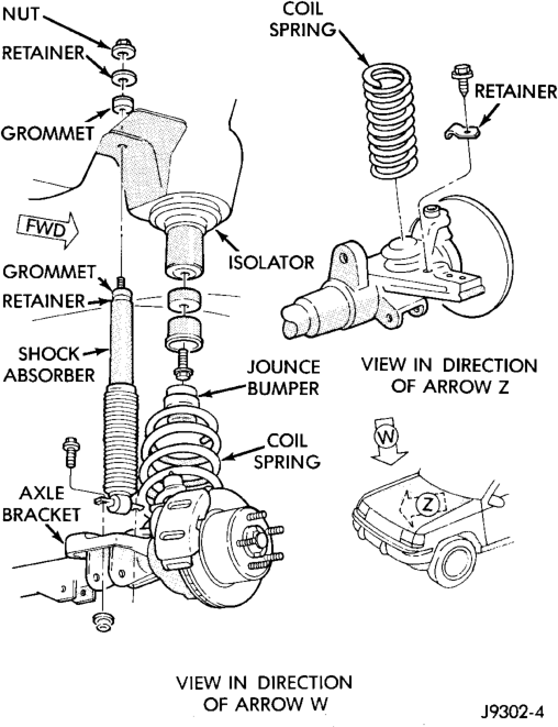
(1) Remove the nut, retainer and grommet from the upper stud in the engine compartment (Fig. 2).
(2) Remove the lower nuts and bolts from the axle bracket. Remove the shock absorber.
INSTALLATION
(1) Position the lower retainer and grommet on the upper stud. Insert the shock absorber through the shock tower hole.
(2) Install the lower bolts and nuts. Tighten nuts to 28 N·m (250 in. lbs.).
(3) Install the upper grommet and retainer on the stud in the engine compartment. Install the nut and tighten to 23 N·m (17 ft. lbs.).
COIL SPRING
REMOVAL
(1) Raise and support the vehicle. Position a hydraulic jack under the axle to support it.
(2) Remove rear lower suspension arm bolts. (3) Remove caliper flex hose brackets from the frame rails.
(4) Remove ABS sensor wires from brackets. (5) Disconnect the stabilizer bar link and shock absorber from the axle.
(6) Disconnect the track bar from the frame rail bracket.
(7) Disconnect the drag link from the pitman arm. (8) Lower the axle until the spring is free from the upper mount. Remove the coil spring retainer bolt (Fig. 2) and remove the spring.
(9) Remove the jounce bumper if necessary from the upper spring mount (Fig. 2).
INSTALLATION
(1) Install the jounce bumper on the upper spring mount.
(2) Position the coil spring on the axle pad. Install the spring retainer and bolt. Tighten bolt to 22 N·m (16 ft lb).
(3) Raise the axle into position until the spring seats in the upper mount.
(4) Install lower suspension arms and rear bolts. (5) Install caliper flex hose brackets to the frame rails.
(6) Install ABS sensor wires into brackets. (7) Connect the stabilizer bar links and shock absorbers to the axle bracket. Connect the track bar to the frame rail bracket.
(8) Install drag link to pitman arm. (9) Remove the supports and lower the vehicle. (10) Tighten all suspension components to proper torque.
STEERING KNUCKLE
For service procedures on the steering knuckle and ball joints refer to Group 3 Differentials And Driveline.
LOWER SUSPENSION ARM
REMOVAL
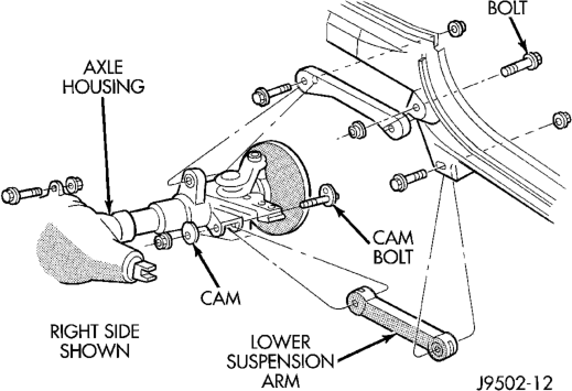
(1) Raise and support the vehicle. (2) Paint or scribe alignment marks on the cam adjusters and suspension arm for installation reference (Fig. 3).
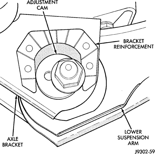
(3) Remove the lower suspension arm nut, cam and cam bolt from the axle (Fig. 4).
(4) Remove the nut and bolt from the frame rail bracket and remove the lower suspension arm (Fig. 4).
INSTALLATION
(1) Position the lower suspension arm at the axle bracket and frame rail bracket.
(2) Install the rear bolts and finger tighten the new nuts.
(3) Install a new cam bolt, cam and new nut in the axle. Re-align the reference marks.
(4) Install the bolts and finger tighten the new nuts.
(5) Lower the vehicle. (6) Tighten the axle bracket nut to 115 N·m (85 ft. lbs.).
(7) Tighten the frame bracket nut to 176 N·m (130 ft. lbs.).
(8) Check the alignment if new parts were installed.
UPPER SUSPENSION ARM
REMOVAL
(1) Raise and support the vehicle. (2) Remove the upper suspension arm nut and bolt at the axle bracket (Fig. 4).
(3) Remove the nut and bolt at the frame rail and remove the upper suspension arm.
INSTALLATION
(1) Position the upper suspension arm at the axle and frame rail.
(2) Install the bolts and finger tighten the nuts. (3) Remove the supports and lower the vehicle. (4) Tighten the nut at the axle and frame bracket to 75 N·m (55 ft. lbs.).
AXLE BUSHING
REMOVAL
(1) Remove the upper suspension arm from axle.
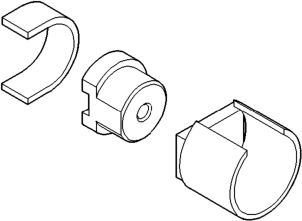
(2) Position spacer 7932-1 (J-35581-1) over the bushing in the axle for two-wheel drive axles and right side on Model 30 axle.
(3) Install Bushing Removal/Installer (Fig. 5). (4) Remove the bushing by tightening the Long Nut.
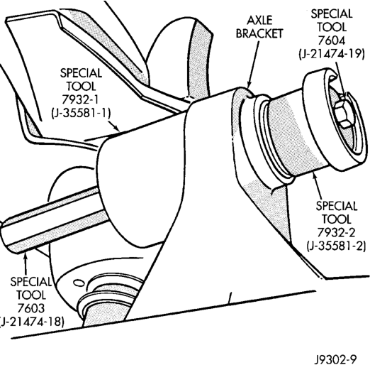
NOTE: For two-wheel drive axles and right side on Model 30 axle, do not remove spacer 7932-1 (J-35581-1). This spacer is need for installation.
INSTALLATION
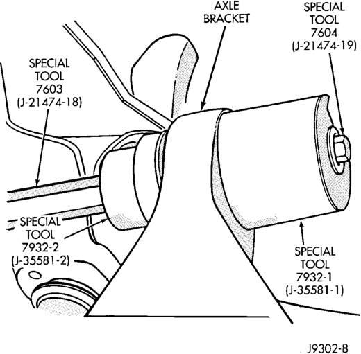
(1) Position new bushing, Receiver and Installer on axle (Fig. 6).
(2) Install the bushing by tightening the Long Nut. (3) Remove tools and install the upper suspension arm.
STABILIZER BAR
REMOVAL
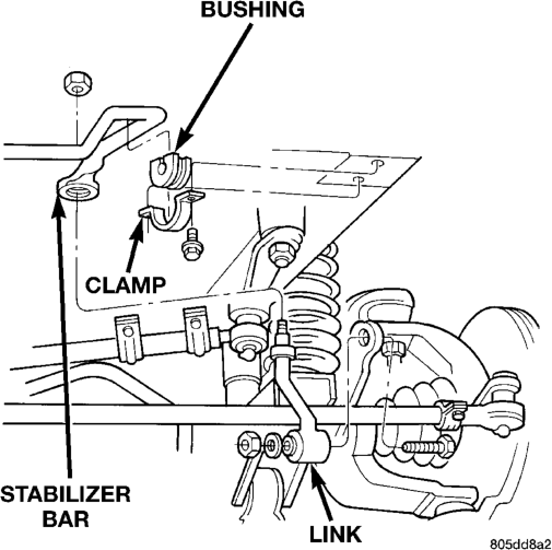
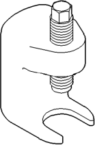
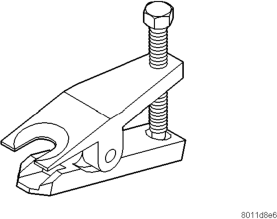
(1) Raise and support the vehicle. (2) Remove upper link bolts (Fig. 7) and separate links from the stabilizer bar with Remover MB-990635.
(3) Remove the stabilizer bar clamps bolts from the frame rails and remove the stabilizer bar.
(4) Remove the stabilizer bar link nuts from the axle brackets (Fig. 7).
INSTALLATION
(1) Position the stabilizer bar on the frame rail and install the clamps and bolts. Ensure the bar is
centered with equal spacing on both sides. Tighten the bolts to 54 N·m (40 ft. lbs.).
(2) Install the links into the stabilizer bar and axle brackets.
(3) Tighten the nuts at the axle bracket end to 95 N·m (70 ft. lbs.).
(4) Tighten the stabilizer bar to link nuts to 61 N·m (45 ft. lbs.).
(5) Remove the supports and lower the vehicle.
(6) Tighten the nuts at the axle bracket end to 95 N·m (70 ft. lbs.).
TRACK BAR
REMOVAL
(1) Raise and support the vehicle. (2) Remove the cotter pin and nut from the ball stud end at the frame rail bracket (Fig. 8).
(3) Use a universal puller to separate the ball stud from the frame rail bracket.
(4) Remove the bolt and flag nut from the axle shaft tube bracket (Fig. 8). Remove the track bar.
INSTALLATION
(1) Install the track bar at axle tube bracket. Loosely install the retaining bolt and flag nut.
(2) It may be necessary to pry the axle assembly over to install the track bar at the frame rail. Install track bar at the frame rail bracket. Install the retaining nut on the stud.
(3) Tighten the ball stud nut to 81 N·m (60 ft. lbs.). Install a new cotter pin.
(4) Remove the supports and lower the vehicle. (5) Tighten the bolt at the axle shaft tube bracket to 75 N·m (55 ft. lbs.).
(6) Check alignment if a new track bar was installed.
HUB BEARING
REMOVAL
(1) Raise and support the vehicle. (2) Remove the wheel and tire assembly. (3) Remove the brake caliper, rotor and ABS wheel speed sensor, refer to Group 5 Brakes.
(4) Remove the cotter pin, nut retainer and axle hub nut (Fig. 9).
(5) Remove the hub mounting bolts and remove hub bearing from the steering knuckle and axle shaft.
INSTALLATION
(1) Install the hub bearing and brake dust shield to the knuckle.
(2) Install the hub to knuckle bolts and tighten to 102 N·m (75 ft. lbs.).
(3) Install the hub washer and nut. Tighten the hub nut to 237 N·m (175 ft. lbs.). Install the nut retainer and a new cotter pin.
(4) Install the brake rotor, caliper and ABS wheel speed sensor, refer to Group 5 Brakes.
(5) Install the wheel and tire assembly. (6) Remove support and lower the vehicle.
WHEEL MOUNTING STUDS
REMOVAL
(1) Raise and support vehicle. (2) Remove wheel and tire assembly. (3) Remove brake caliper and rotor, refer to Group 5 Brakes for procedure.
(4) Remove stud from hub with Remover C-4150A (Fig. 10).
INSTALLATION
(1) Install new stud into hub flange. (2) Install three washers onto stud, then install lug nut with the flat side of the nut against the washers.
(3) Tighten lug nut until the stud is pulled into the hub flange. Verify that the stud is properly seated into the flange.
(4) Remove lug nut and washers. (5) Install the brake rotor and caliper, refer to Group 5 Brakes for procedure.
(6) Install wheel and tire assembly, use new lug nut on stud or studs that were replaced.
(7) Remove support and lower vehicle.
SPECIFICATIONS
TORQUE CHART
DESCRIPTION TORQUE Shock Absorber
Upper Nut . . . . . . . . . . . . . . . . .23 N·m (17 ft. lbs.) Lower Nut . . . . . . . . . . . . . . . . .28 N·m (21 ft. lbs.) Suspension Arm Upper
Nuts . . . . . . . . . . . . . . . . . . . . .75 N·m (55 ft. lbs.) Suspension Arm Lower
Axle Bracket Nut. . . . . . . . . . .115 N·m (85 ft. lbs.) Frame Bracket Nut . . . . . . . .176 N·m (130 ft. lbs.) Stabilizer Bar
Clamp Bolt . . . . . . . . . . . . . . . .54 N·m (40 ft. lbs.) Link Upper Nut. . . . . . . . . . . . .61 N·m (45 ft. lbs.) Link Lower Bolt . . . . . . . . . . . .95 N·m (70 ft. lbs.) Track Bar
Ball Stud Nut . . . . . . . . . . . . . .81 N·m (60 ft. lbs.) Axle Bracket Bolt . . . . . . . . . . .75 N·m (55 ft. lbs.) Track Bar Bracket
Bolts . . . . . . . . . . . . . . . . . . . .121 N·m (90 ft. lbs.) Nut . . . . . . . . . . . . . . . . . . . . .121 N·m (90 ft. lbs.) Support Bolts . . . . . . . . . . . . . .95 N·m (70 ft. lbs.) Hub Bearing Bolts . . . . . . . . . . . . . . . . . . . . . .102 N·m (75 ft. lbs.)
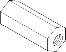
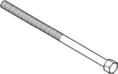
SPECIAL TOOLS
FRONT SUSPENSION
(J-35581)
DESCRIPTION AND OPERATION
REAR SUSPENSION . . . . . . . . . . . . . . . . . . . . . 12 DIAGNOSIS AND TESTING
SHOCK DIAGNOSIS . . . . . . . . . . . . . . . . . . . . . . 13 REMOVAL AND INSTALLATION
COIL SPRING . . . . . . . . . . . . . . . . . . . . . . . . . . . 13 LOWER SUSPENSION ARM . . . . . . . . . . . . . . . . 13
DESCRIPTION AND OPERATION
REAR SUSPENSION
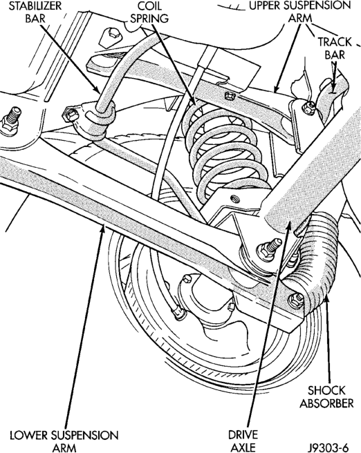
The rear suspension is link/coil design comprised of (Fig. 1):
• Drive axle • Dual-action shock absorbers • Coil springs • Upper and lower suspension arms • Track bar • Stabilizer bar
REAR SUSPENSION
INDEX
page page
SHOCK ABSORBER . . . . . . . . . . . . . . . . . . . . . . 13 STABILIZER BAR . . . . . . . . . . . . . . . . . . . . . . . . 14 TRACK BAR . . . . . . . . . . . . . . . . . . . . . . . . . . . . 14 UPPER SUSPENSION ARM . . . . . . . . . . . . . . . . 14 SPECIFICATIONS
TORQUE CHART . . . . . . . . . . . . . . . . . . . . . . . . 15
Upper And Lower Suspension: The suspension arms use bushings to isolate road noise. The suspension arms are bolted to the body and axle through the rubber bushings. The lower suspension arm has provision for the use of cam bolts at the axle to allow for pinion angle or thrust angle adjustment. The cams are available as a service kit and are not installed at the factory. The suspension arm travel is limited through the of use jounce bumpers in compression and shock absorbers in rebound.
Shock Absorbers: The shock absorbers dampen jounce and rebound of the vehicle over various road conditions. The top of the shock absorbers are bolted to the body. The bottom of the shocks are bolted to the axle shock absorber bracket.
Coil Springs: The coil springs mount up in the fender shield that is part of the unitized body bracket. There is a rubber isolator between the top of the spring and bracket to isolate road noise. The bottom of the spring seats on the axle pad and is retained with a clip.
Stabilizer Bar: The stabilizer bar is used to control vehicle body roll during turns. The spring steel bar helps to equalize the vehicle body in relationship to the suspension. The bar extends across the underside of the chassis and connects to the frame rails. Links are connected from the bar to the axle brackets. Stabilizer bar are isolated by rubber bushings.
Track Bar: The track bar is used to control rear axle lateral movement. The track bar is attached to a frame rail bracket and an axle bracket. It is isolated with bushings at both ends.
CAUTION: Suspension components with rubber/ urethane bushings (except stabilizer bar) should be tightened with the vehicle at normal ride height. It is important to have the springs supporting the weight of the vehicle when the fasteners are torqued. This will maintain vehicle ride comfort and prevent premature bushing wear.
DIAGNOSIS AND TESTING
SHOCK DIAGNOSIS
A knocking or rattling noise from a shock absorber may be caused by movement between mounting bushings and metal brackets or attaching components. These noises can usually be stopped by tightening the attaching nuts. If the noise persists, inspect for damaged and worn bushings, and attaching components. Repair as necessary if any of these conditions exist.
A squeaking noise from the shock absorber may be caused by the hydraulic valving and may be intermittent. This condition is not repairable and the shock absorber must be replaced.
The shock absorbers are not refillable or adjustable. If a malfunction occurs, the shock absorber must be replaced. To test a shock absorber, hold it in an upright position and force the piston in and out of the cylinder four or five times. The action throughout each stroke should be smooth and even.
The shock absorber bushings do not require any type of lubrication. Do not attempt to stop bushing noise by lubricating them. Grease and mineral oilbase lubricants will deteriorate the bushing.
REMOVAL AND INSTALLATION
SHOCK ABSORBER
REMOVAL
(1) Raise and support the vehicle. Position a hydraulic jack under the axle to support it.
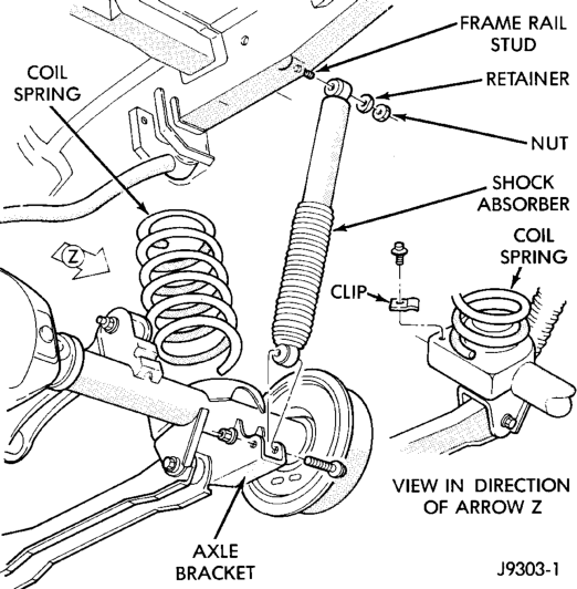
(2) Remove the upper nut and retainer from the frame rail stud (Fig. 2).
(3) Remove the lower nut and bolt from the axle bracket. Remove the shock absorber.
INSTALLATION
(1) Install the shock absorber on the upper frame rail stud. Install the shock absorber on the axle bracket.
(2) Install the retainer and nut on the stud. Tighten the upper nut to 70 N·m (52 ft. lbs.).
(3) Install lower bolt and nut finger tight. (4) Remove the supports and lower the vehicle. (5) Tighten the lower nut to 92 N·m (68 ft. lbs.).
COIL SPRING
REMOVAL
(1) Raise and support the vehicle. Position a hydraulic jack under the axle to support it.
(2) Disconnect the stabilizer bar link and shock absorber from the axle bracket.
(3) Disconnect the track bar from the frame rail bracket.
(4) Lower the axle until the spring is free from the upper mount seat. Remove the coil spring retainer bolt (Fig. 2) and remove the spring.
INSTALLATION
Inspect isolator for damage or wear. Replace the isolator if necessary before installing spring. (1) Position the coil spring on the axle pad. Install the spring retainer and bolt. Tighten the bolt to 22 N·m (16 ft. lbs.).
(2) Raise the axle into position until the spring seats in the upper mount.
(3) Connect the stabilizer bar links and shock absorbers to the axle bracket. Connect the track bar to the frame rail bracket.
(4) Remove the supports and lower the vehicle. (5) Tighten the track bar and shock absorber to specified torque.
LOWER SUSPENSION ARM
REMOVAL
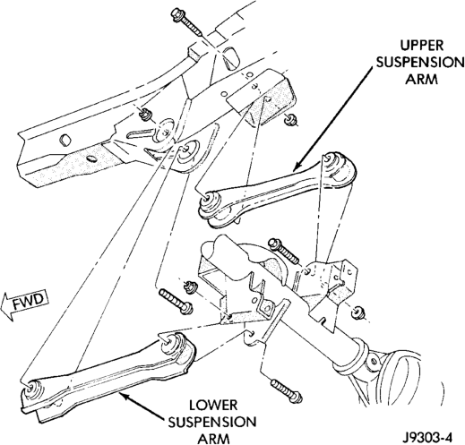
(1) Raise and support the vehicle. (2) Remove the lower suspension arm nut and bolt at the axle bracket (Fig. 3).
(3) Remove the nut and bolt (Fig. 3) at the frame rail and remove the lower suspension arm.
INSTALLATION
(1) Position the lower suspension arm at the axle bracket and frame rail bracket.
(2) Install the bolts and finger tighten the nuts. (3) Remove the supports and lower the vehicle. (4) Tighten the lower suspension arm nuts to 177 N·m (130 ft. lbs.).
UPPER SUSPENSION ARM
REMOVAL
(1) Raise and support the vehicle. (2) Remove the upper suspension arm nut and bolt at the axle bracket (Fig. 3). Remove the ABS wire bracket from the arm.
(3) Remove the nut and bolt at the frame rail and remove the upper suspension arm.
INSTALLATION
(1) Position the upper suspension arm at the axle and frame rail.
(2) Install the bolts and finger tighten the nuts. Install the ABS wire bracket onto the arm.
(3) Remove the supports and lower the vehicle. (4) Tighten the upper suspension arm nuts to 75 N·m (55 ft. lbs.).
STABILIZER BAR
REMOVAL
(1) Raise and support the vehicle. Remove one wheel and tire.
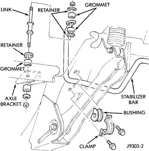
(2) Disconnect the stabilizer bar links from the axle brackets (Fig. 4).
(3) Lower the exhaust by disconnecting the muffler and tail pipe hangers.
(4) Disconnect the stabilizer bar from the links.
(5) Disconnect the stabilizer bar clamps from the frame rails. Remove the stabilizer bar.
INSTALLATION
(1) Position the stabilizer bar on the frame rail and install the clamps and bolts. Ensure the bar is centered with equal spacing on both sides. Tighten the bolts to 54 N·m (40 ft. lbs.).
(2) Install the links and grommets onto the stabilizer bar and axle brackets. Install the nuts and tighten to 36 N·m (27 ft. lbs.).
(3) Connect the muffler and tail pipe to their hangers.
(4) Install the wheel and tire assembly.
TRACK BAR
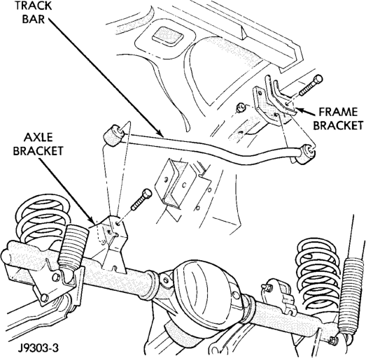
REMOVAL
(1) Raise and support the vehicle. (2) Remove the bolt and nut from the frame rail bracket (Fig. 5).
(3) Remove the bolt from the axle tube bracket (Fig. 5). Remove the track bar.
INSTALLATION
(1) Install the track bar to the axle bracket and install a new bolt. (2) It may be necessary to pry the axle assembly over to install the track bar. Install the track bar to the frame rail bracket. Loosely install the bolt and flag nut.
(3) Remove the supports and lower the vehicle. (4) Tighten the track bar bolts 100 N·m (74 ft. lbs.).
SPECIFICATIONS
TORQUE CHART
DESCRIPTION TORQUE Shock Absorber
Upper Nut. . . . . . . . . . . . . . . . .70 N·m (52 ft. lbs.) Lower Nut. . . . . . . . . . . . . . . . .92 N·m (68 ft. lbs.) Suspension Arm Upper
Nuts . . . . . . . . . . . . . . . . . . . . .75 N·m (55 ft. lbs.) Suspension Arm Lower
Nuts . . . . . . . . . . . . . . . . . . .177 N·m (130 ft. lbs.) Stabilizer Bar
Clamp Bolt . . . . . . . . . . . . . . . .54 N·m (40 ft. lbs.) Link Nut. . . . . . . . . . . . . . . . . .36 N·m (27 ft. lbs.) Track Bar
Frame Bracket Nut. . . . . . . . .100 N·m (74 ft. lbs.) Axle Bracket Bolt . . . . . . . . . .100 N·m (74 ft. lbs.)