Speed Control System — 1998 Jeep Grand Cherokee ZJ Export Service Manual
Pages 463–469 · 7 pages · 0 words repaired
control switch functions and setting procedures. The individual switches cannot be repaired. If one individual switch fails, the switch module must be replaced.
STOP LAMP SWITCH
Vehicles equipped with the speed control option use a dual function stop lamp switch. The switch is mounted in the same location as the conventional stop lamp switch, on the brake pedal mounting bracket under the instrument panel. The PCM monitors the state of the dual function stop lamp switch. Refer to Group 5, Brakes for more information on stop lamp switch service and adjustment procedures.
SERVO CABLE
The speed control servo cable is connected between the speed control vacuum servo diaphragm and the throttle body control linkage. This cable causes the throttle control linkage to open or close the throttle valve in response to movement of the vacuum servo diaphragm.
POWERTRAIN CONTROL MODULE
The speed control electronic control circuitry is integrated into the Powertrain Control Module (PCM). The PCM is located in the engine compartment. The PCM speed control functions are monitored by the On-Board Diagnostics (OBD). All OBD- sensed systems are monitored by the PCM. Each monitored circuit is assigned a Diagnostic Trouble Code (DTC). The PCM will store a DTC in electronic memory for certain failures it detects. See On-Board Diagnostic Test For Speed Control System in this group for more information. The PCM cannot be repaired and must be replaced if faulty.
VACUUM RESERVOIR
A vacuum reservoir is used to supply the vacuum needed to maintain proper speed control operation when engine vacuum drops, such as in climbing a grade while driving. A one-way check valve is used in the vacuum line between the reservoir and the vacuum source. This check valve is used to trap engine vacuum in the reservoir. On certain vehicle applications, this reservoir is shared with the heating/airconditioning system. The vacuum reservoir cannot be repaired and must be replaced if faulty.
VEHICLE SPEED SENSOR
The Vehicle Speed Sensor (VSS) is a pulse generator mounted to an adapter near the transmission output shaft. The sensor is driven through the adapter by a speedometer pinion gear. The VSS pulse signal to the speedometer/odometer is monitored by the
PCM speed control circuitry to determine vehicle speed and to maintain speed control set speed.
DIAGNOSIS AND TESTING
ROAD TEST
Perform a vehicle road test to verify reports of speed control system malfunction. The road test should include attention to the speedometer. Speedometer operation should be smooth and without flutter at all speeds.
Flutter in the speedometer indicates a problem which might cause surging in the speed control system. The cause of any speedometer problems should be corrected before proceeding. Refer to Group 8E, Instrument Panel and Gauges for speedometer diagnosis.
If a road test verifies a system problem and the speedometer operates properly, check for:
• A Diagnostic Trouble Code (DTC). If a DTC exists, conduct tests per the Powertrain Diagnostic Procedures service manual.
• A misadjusted brake (stop) lamp switch. This could also cause an intermittent problem.
• Loose, damaged or corroded electrical connections at the servo. Corrosion should be removed from electrical terminals and a light coating of Mopar MultiPurpose Grease, or equivalent, applied.
• Leaking vacuum reservoir. • Loose or leaking vacuum hoses or connections. • Defective one-way vacuum check valve. • Secure attachment of both ends of the speed control servo cable.
• Smooth operation of throttle linkage and throttle body air valve.
• Failed speed control servo. Do the servo vacuum test.
CAUTION: When test probing for voltage or continuity at electrical connectors, care must be taken not to damage connector, terminals or seals. If these components are damaged, intermittent or complete system failure may occur.
ON-BOARD DIAGNOSTIC TEST FOR SPEED CONTROL SYSTEM
The Powertrain Control Module (PCM) monitors critical input and output circuits of the speed control system, making sure they are operational. A Diagnostic Trouble Code (DTC) is assigned to each input and output circuit monitored by the On-Board Diagnostic (OBD) system. Some circuits are checked continuously and some are checked only under certain conditions.
For DTC information, refer to Diagnostic Trouble Codes in Group 25, Emission Control System. This will include a complete list of DTC's including DTC's for the speed control system.
VEHICLE SPEED SENSOR
For diagnosis and testing of the Vehicle Speed Sensor (VSS), refer to the appropriate Powertrain Diagnostic Procedures service manual. Also refer to the DRB scan tool.
SPEED CONTROL SWITCHES
For complete speed control system diagnosis, refer to the appropriate Powertrain Diagnostic Procedures manual. To test each of the speed control switches only, refer to the following:
WARNING: BEFORE ATTEMPTING TO DIAGNOSE, REMOVE OR INSTALL ANY AIRBAG SYSTEM OR RELATED STEERING WHEEL AND STEERING COL- UMN COMPONENTS, YOU MUST FIRST DISCON- NECT AND ISOLATE THE BATTERY NEGATIVE (GROUND) CABLE. WAIT 2 MINUTES FOR SYSTEM CAPACITOR TO DISCHARGE BEFORE FURTHER SYSTEM SERVICE. FAILURE TO DO SO COULD RESULT IN ACCIDENTAL AIRBAG DEPLOYMENT AND POSSIBLE PERSONAL INJURY.
(1) Disconnect negative battery cable. Wait 2 minutes for airbag system capacitor to discharge.
(2) Remove the two speed control switch modules from steering wheel. Refer to the removal/installation section for procedures.
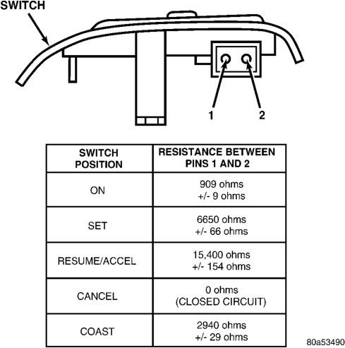
(3) Check continuity of each individual speed control switch module as shown in chart (Fig. 1). If OK, reinstall switch. If not OK, replace switch module assembly.
STOP LAMP SWITCH
For continuity checks and switch adjustment, refer to Group 5, Brakes.
VACUUM SUPPLY TEST
(1) Disconnect vacuum hose at speed control servo and install a vacuum gauge into the disconnected hose.
(2) Start engine and observe gauge at idle. Vacuum gauge should read at least ten inches of mercury.
(3) If vacuum is less than ten inches of mercury, determine source of leak. Check vacuum line to engine for leaks. Also check actual engine intake manifold vacuum. If manifold vacuum does not meet this requirement, check for poor engine performance and repair as necessary.
(4) If vacuum line to engine is not leaking, check for leak at vacuum reservoir. To locate and gain
access to reservoir, refer to Vacuum Reservoir Removal/Installation in this group. Disconnect vacuum line at reservoir and connect a hand-operated vacuum pump to reservoir fitting. Apply vacuum. Reservoir vacuum should not bleed off. If vacuum is being lost, replace reservoir.
(5) Verify operation of one-way check valve and check it for leaks.
(a) Locate one-way check valve. The valve is located in vacuum line between vacuum reservoir and engine vacuum source. Disconnect vacuum hoses (lines) at each end of valve.
(b) Connect a hand-operated vacuum pump to reservoir end of check valve. Apply vacuum. Vacuum should not bleed off. If vacuum is being lost, replace one-way check valve.
(c) Connect a hand-operated vacuum pump to vacuum source end of check valve. Apply vacuum. Vacuum should flow through valve. If vacuum is not flowing, replace one-way check valve. Seal the fitting at opposite end of valve with a finger and apply vacuum. If vacuum will not hold, diaphragm within check valve has ruptured. Replace valve.
SPEED CONTROL SERVO
For complete speed control system diagnosis, refer to the appropriate Powertrain Diagnostic Procedures manual. To test the speed control servo only, refer to the following:
The engine must be started and running for the following voltage tests.
(1) Start engine. (2) Disconnect 4–way electrical connector at servo.
(3) Turn speed control switch to ON position. (4) Check for battery voltage at pin–3 of wiring harness 4–way connector (Fig. 2). This is the 12 volt feed from the stoplamp switch. When the brake pedal is depressed, voltage should not be present at pin–3. If voltage is not present with brake pedal not depressed, check for continuity between servo and stop lamp switch. Also check stop lamp switch adjustment. Refer to Group 5, Brakes for procedures.
(5) Connect a small gauge jumper wire between the disconnected servo harness 4–way connector pin–3, and pin–3 on the servo. Check for battery voltage at pins–1, 2 and 4 of the servo. If battery voltage is not at these pins, replace the servo.
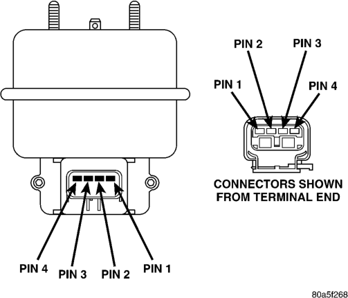
(6) Turn ignition switch to OFF position. Check for continuity between disconnected servo harness 4–way connector pin–4 and a good ground. There should be continuity. If not OK, repair open circuit to ground as required.
OVERSHOOT/UNDERSHOOT FOLLOWING SPEED CONTROL SET
If the operator repeatedly presses and releases the set button with their foot off of the accelerator (a “lift foot set” to begin speed control operation), the vehicle may accelerate and exceed the desired set speed by up to 5 MPH (8 km/h) and then decelerate to less than the desired set speed before finally achieving the desired set speed.
The Speed Control has an adaptive strategy that compensates for vehicle-to-vehicle variations in speed control cable lengths. When the speed control is set with the vehicle operators foot off of the accelerator pedal, the speed control thinks there is excessive speed control cable slack and adapts. If the lift foot sets are continually used, the speed control overshoot/undershoot condition will develop.
To “unlearn” the overshoot/undershoot condition, the vehicle operator has to press and release the set button while maintaining the desired set speed with the accelerator pedal (not decelerating or accelerating), and then turn the cruise control switch to the OFF position (or press the CANCEL button if equipped) after waiting 10 seconds. This procedure must be performed approximately 10–15 times to completely unlearn the overshoot/undershoot condition.
REMOVAL AND INSTALLATION
SPEED CONTROL SERVO
REMOVAL
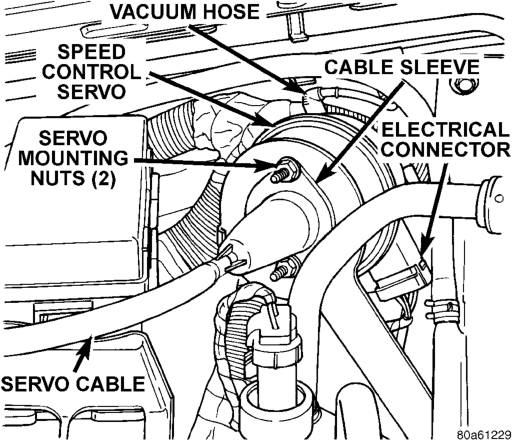
(1) Disconnect negative battery cable at battery. (2) Disconnect vacuum line at servo (Fig. 3). (3) Disconnect electrical connector at servo. (4) Disconnect servo cable at throttle body. Refer to Servo Cable Removal/Installation in this group.
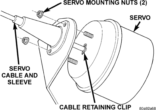
(5) Remove 2 mounting nuts holding servo cable sleeve to bracket (Fig. 3) or (Fig. 4).
(6) Pull speed control cable sleeve and servo away from servo mounting bracket to expose cable retaining clip (Fig. 4) and remove clip. Note: The servo mounting bracket displayed in (Fig. 4) is a typical bracket and may/may not be applicable to this model vehicle.
(7) Remove servo from mounting bracket.
INSTALLATION
(1) Position servo to mounting bracket. (2) Align hole in cable connector with hole in servo pin. Install cable-to-servo retaining clip.
(3) Insert servo mounting studs through holes in servo mounting bracket.
(4) Install servo mounting nuts and tighten to 8.5 N·m (75 in. lbs.).
(5) Connect vacuum line at servo. (6) Connect electrical connector at servo. (7) Connect servo cable to throttle body. Refer to Servo Cable Removal/Installation in this group.
(8) Connect negative battery cable to battery. (9) Before starting engine, operate accelerator pedal to check for any binding.
SPEED CONTROL SWITCHES
REMOVAL
WARNING: BEFORE BEGINNING ANY AIRBAG SYSTEM COMPONENT REMOVAL OR INSTALLA- TION, REMOVE AND ISOLATE THE NEGATIVE (-) CABLE FROM THE BATTERY. THIS IS THE ONLY SURE WAY TO DISABLE THE AIRBAG SYSTEM. THEN WAIT TWO MINUTES FOR SYSTEM CAPACI- TOR TO DISCHARGE BEFORE FURTHER SYSTEM SERVICE. FAILURE TO DO THIS COULD RESULT IN ACCIDENTAL AIRBAG DEPLOYMENT AND POSSI- BLE INJURY.
(1) Disconnect and isolate negative battery cable. (2) Remove airbag module. Refer to Group 8M, Passive Restraint Systems for procedures.
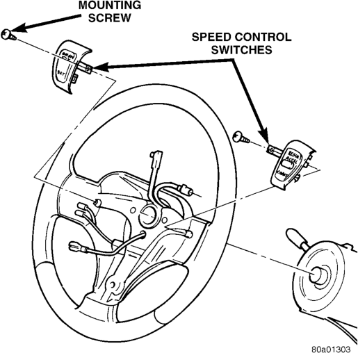
(3) Remove electrical connector at switch. (4) Remove switch-to-steering wheel mounting screw (Fig. 5).
(5) Remove switch.
INSTALLATION
(1) Install switch and mounting screw. (2) Tighten screw to 1.5 N·m (15 in. lbs.) torque.
(3) Install electrical connector to switch. (4) Install airbag module. Refer to Group 8M, Passive Restraint Systems for procedures.
(5) Connect negative battery cable.
STOP LAMP SWITCH
Refer to Stop Lamp Switch in Group 5, Brakes for removal/installation and adjustment procedures.
SERVO CABLE
REMOVAL
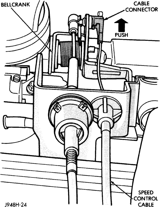
(1) Disconnect negative battery cable at battery. (2) 4.0L Engine: Using finger pressure only, remove speed control cable connector at throttle body bellcrank pin by pushing connector off the bellcrank towards the drivers side of vehicle (Fig. 6). DO NOT try to pull connector off perpendicular to the bellcrank pin. Connector will be broken.
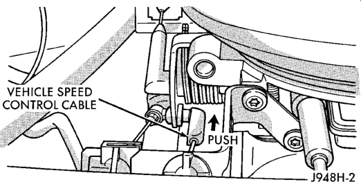
(3) 5.2L/5.9L Engines: Using finger pressure only, remove speed control cable connector at throttle body bellcrank by pushing connector rearward off the bellcrank pin (Fig. 7). DO NOT try to pull connector off perpendicular to the bellcrank pin. Connector will be broken.
(4) 4.0L Engine: Remove cable from cable guide at top of valve cover.
(5) Squeeze 2 tabs on sides of speed control cable at throttle body mounting bracket (locking plate) and push out of bracket.
(6) Remove servo cable from servo. Refer to Speed Control Servo Removal/Installation in this group.
INSTALLATION
(1) Install end of cable to speed control servo. Refer to Speed Control Servo removal and installation in this group.
(2) Install cable into throttle body mounting bracket (snaps in).
(3) Install speed control cable connector at throttle body bellcrank pin (snaps on).
(4) Connect negative battery cable at battery. (5) Before starting engine, operate accelerator pedal to check for any binding.
VACUUM RESERVOIR
The vacuum reservoir is located under the vehicle battery tray.
REMOVAL
(1) Disconnect both battery cables at battery (negative cable first).
(2) Remove battery. Refer to Group 8A, Battery for procedure.
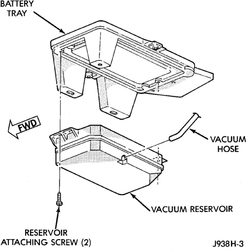
(3) Remove 5 bolts securing battery tray. (4) Pull up battery tray and remove vacuum hose from reservoir (Fig. 8).
(5) Remove 2 screws holding reservoir to battery tray.
INSTALLATION
(1) Install vacuum reservoir. Tighten bolts (screws) to 3 N·m (30 in. lbs.) torque.
(2) Connect vacuum hose at reservoir. (3) Install battery tray mounting bolts. Tighten to 10 N·m (90 in. lbs.) torque.
(4) Install battery. (5) Install battery holddown and bolts. Tighten to 10 N·m (90 in. lbs.) torque.
(6) Install battery cable clamp bolts. Tighten to 8.5 N·m (75 in. lbs.) torque.
SPECIFICATIONS
TORQUE CHART
Description Torque Servo Mounting
Bracket-to-Servo Nuts. . . . . . .8.5 N·m (75 in. lbs.) Servo Mounting
Bracket-to-Body Nuts. . . . . . . . .5 N·m (47 in. lbs.) Switch Module
Mounting Screws. . . . . . . . . . .1.5 N·m (15 in. lbs.) Vacuum Reservoir
Mounting Bolts . . . . . . . . . . . . .3 N·m (30 in. lbs.)