Power Window Systems — 1998 Jeep Grand Cherokee ZJ Export Service Manual
Pages 519–525 · 7 pages · 3 words repaired
ule (PDM), respectively. These power window switches provide an up or down (or lock and unlock signal in the case of the lockout switch) to the door module circuitry.
The DDM circuitry controls the output to the driver side front and rear door power window motors, and supplies electrical current as required for the stand-alone operation of the driver side rear door power window switch. The PDM circuitry controls the output to the passenger side front and rear door power window motors, and supplies electrical current as required for the stand-alone operation of the passenger side rear door power window switch. When a DDM-integrated power window switch for a passenger side window is actuated, the DDM circuitry sends a message to the PDM on the Chrysler Collision Detection (CCD) data bus to activate the output to that power window motor(s).
The front door power window switches and their lamps cannot be repaired so, if faulty or damaged, the entire door module must be replaced. The rear door power window switches and their lamps cannot be repaired but, if faulty or damaged, only the affected rear door switch must be replaced.
DOOR MODULE
A Driver Door Module (DDM) and a Passenger Door Module (PDM) are used on this model to control and integrate many of the electronic features and functions on the vehicle. Each door module houses both the front power lock and power window switches. The DDM also houses individual switches for each passenger door power window, a power window lockout switch and the power mirror switch.
The DDM and PDM communicate with each other, and with other vehicle modules on the Chrysler Collision Detection (CCD) data bus network. The CCD data bus network allows the sharing of sensor information. This helps to reduce wire harness complexity, internal controller hardware, and component sensor current loads. At the same time, this system provides increased reliability, enhanced diagnostics, and allows the addition of many new feature capabilities.
The DDM circuitry controls the output to the driver side front and rear door power windows. The PDM circuitry controls the output to the passenger side front and rear door power windows. The DDM can control the PDM output by sending control messages to the PDM over the CCD data bus.
Some of the features and functions of the power window system made possible because of the communication of the door modules on the CCD data bus network include:
• Power window operation after ignition off feature.
• Power window lockout function.
• Power window switch LED illumination control function.
For diagnosis of the DDM, PDM, or the CCD data bus network, a DRB scan tool and the proper Diagnostic Procedures manual are recommended. The DDM and the PDM cannot be repaired and, if damaged or faulty, they must be replaced.
BODY CONTROL MODULE
A Body Control Module (BCM) is used on this model to control and integrate many of the electronic functions and features included on the vehicle. The BCM contains a central processing unit and interfaces with other modules in the vehicle on the Chrysler Collision Detection (CCD) data bus network.
The CCD data bus network allows the sharing of sensor information. This helps to reduce wire harness complexity, reduce internal controller hardware, and reduce component sensor current loads. At the same time, this system provides increased reliability, enhanced diagnostics, and allows the addition of many new feature capabilities.
One of the functions and features that the BCM supports and controls, is the power window system. The BCM receives inputs from the ignition switch and the door ajar switches. The programming in the BCM allows it to process the information from these inputs and send ignition switch and door ajar status messages to the Driver Door Module (DDM) and the Passenger Door Module (PDM) on the CCD data bus. The DDM and PDM use this information to control the lighting of the power window switch lamps, and to control the operation of the power window after ignition-off feature. The BCM is mounted under the driver side outboard end of the instrument panel, behind the instrument panel support armature and below the outboard switch pod. Refer to Group 8E - Instrument Panel Systems for the removal and installation procedures. For diagnosis of the BCM or the CCD data bus, the use of a DRB scan tool and the proper Diagnostic Procedures manual are recommended. The BCM can only be serviced by an authorized electronic repair station. Refer to the latest Warranty Policies and Procedures manual for a current listing of authorized electronic repair stations.
POWER WINDOW MOTOR
A permanent magnet reversible motor moves the window regulator through an integral gearbox mechanism. A positive and negative battery connection to the two motor terminals will cause the motor to rotate in one direction. Reversing the current through these same two connections will cause the motor to rotate in the opposite direction.
In addition, each power window motor is equipped with an integral self-resetting circuit breaker to protect the motor from overloads. The power window motor and gearbox assembly cannot be repaired and, if faulty or damaged, the entire motor assembly must be replaced.
CIRCUIT BREAKER
An automatic resetting circuit breaker in the junction block is used to protect the power window system circuit. The circuit breaker can protect the system from a short circuit, or from an overload condition caused by an obstructed or stuck window glass or regulator.
The circuit breaker cannot be repaired and, if faulty, it must be replaced.
DIAGNOSIS AND TESTING
POWER WINDOW SYSTEM
NOTE: The following tests may not prove conclusive in the diagnosis of this component. The most reliable, efficient, and accurate means to diagnose this system involves the use of a DRB scan tool and the proper Diagnostic Procedures manual.
Remember, the Driver Door Module (DDM) circuitry controls the output to the driver side front and rear power window motors. The Passenger Door Module (PDM) circuitry controls the output to the passenger side front and rear power window motors. For circuit descriptions and diagrams, refer to 8W-60 - Power Windows in Group 8W - Wiring Diagrams.
ALL WINDOWS INOPERATIVE
(1) Check the circuit breaker in the junction block, as described in this group. If OK, go to Step 2. If not OK, replace the faulty circuit breaker.
(2) Disconnect and isolate the battery negative cable. Remove the left and right front door trim panels. Check the 12-way door module wire harness connectors to see that they are fully seated in the door module receptacles. If OK, go to Step 3. If not OK, install the wire harness connectors properly. (3) Unplug the 12-way door module wire harness connectors. Check for continuity between the ground circuit cavity of each door module wire harness connector and a good ground. If OK, go to Step 4. If not OK, repair the open circuit as required.
(4) Connect the battery negative cable. Check for battery voltage at the fused B(+) circuit cavity of each 12-way door module wire harness connector. If OK, use a DRB scan tool and the proper Diagnostic Procedures manual to diagnose the door modules and the CCD data bus. If not OK, repair the open circuit to the junction block as required.
ONE WINDOW INOPERATIVE
The window glass must be free to slide up and down for the power window motor to function properly. If the glass is not free to move up and down, the motor will overload and trip the integral circuit breaker. To determine if the glass is free, disconnect the regulator plate from the glass. Then slide the window up and down by hand.
There is an alternate method to check if the glass is free. Position the glass between the up and down stops. Then, shake the glass in the door. Check that the glass can be moved slightly from side to side, front to rear, and up and down. Then check that the glass is not bound tight in the tracks. If the glass is free, proceed to the Door Module diagnosis in this group. If the glass is not free, refer to Group 23 - Body for the door window glass and hardware service and adjustment procedures.
CIRCUIT BREAKER
For circuit descriptions and diagrams, refer to 8W-60 - Power Windows in Group 8W - Wiring Diagrams.
(1) Locate the circuit breaker in the junction block. Pull out the circuit breaker slightly, but be sure that the terminals still contact the terminals in the junction block cavities.
(2) Connect the negative lead of a 12-volt DC voltmeter to a good ground.
(3) With the voltmeter positive lead, check both terminals of the circuit breaker for battery voltage.
If only one terminal has battery voltage, the circuit breaker is faulty and must be replaced. If neither terminal has battery voltage, repair the open circuit from the Power Distribution Center (PDC) as required. If the circuit breaker checks OK, but no power windows operate, see the diagnosis for Power Window System in this group.
DOOR MODULE
NOTE: The following tests may not prove conclusive in the diagnosis of this component. The most reliable, efficient, and accurate means to diagnose this system involves the use of a DRB scan tool and the proper Diagnostic Procedures manual.
If the problem being diagnosed is a rear door window that does not operate from the rear door switch, but does operate from the master switch on the driver side front door, go to the diagnosis for Power Window Switch in this group. If the problem is a passenger side front or rear window that operates from the switch on that door, but does not operate from the master switch on the driver side front door, use a DRB scan tool and the proper Diagnostic Procedures manual to diagnose the circuitry of both door modules and the CCD data bus. For circuit descriptions and diagrams, refer to 8W-60 - Power Windows in Group 8W - Wiring Diagrams.
(1) Disconnect and isolate the battery negative cable. Remove the front door trim panel as described in this group. Go to Step 2. (2) Check the 12-way door module wire harness connector to see that it is fully seated in the door module receptacle. If OK, go to Step 3. If not OK, install the wire harness connector properly. (3) Unplug the 12-way door module wire harness connector from the door module. Check for continuity between the ground circuit cavity of the door module wire harness connector and a good ground. There should be continuity. If OK, go to Step 4. If not OK, repair the open circuit as required.
(4) Connect the battery negative cable. Check for battery voltage at the fused B(+) circuit cavity of the 12-way door module wire harness connector. If OK, go to Step 5. If not OK, repair the open circuit as required.
(5) If the inoperative window is on a front door, go to Step 6. If the inoperative window is on a rear door go to Step 9.
(6) Disconnect and isolate the battery negative cable. Unplug the inoperative power window motor wire harness connector. Check for continuity between the front window driver up circuit cavity of the 12-way door module wire harness connector and a good ground. Repeat the check for the front window driver down circuit cavity of the door module wire harness connector. In each case there should be no continuity. If OK, go to Step 7. If not OK, repair the short circuit as required.
(7) Check for continuity between the front window driver up circuit cavities of the 12-way door module wire harness connector and the power window motor wire harness connector. Repeat the check for the front window driver down circuit cavities. In each case there should be continuity. If OK, go to Step 8. If not OK, repair the open circuit as required.
(8) Plug the 12-way door module wire harness connector back into the door module. Connect the battery negative cable. Connect the probes of a reversible DC digital voltmeter to the door module side of the power window motor wire harness connector. Observe the voltmeter while actuating the switch in the up and down directions. There should be battery voltage for as long as the switch is held in both the up and down positions, and no voltage in the neutral position. If OK, see the diagnosis for Power Window Motors in this group. If not OK, replace the faulty door module.
(9) Disconnect and isolate the battery negative cable. Remove the rear door power window switch as described in this group. Check the rear door power window switch continuity as described in this group. If OK, go to Step 10. If not OK, replace the faulty switch.
(10) Plug the rear door power window switch into the wire harness connector. Unplug the inoperative power window motor wire harness connector. Check for continuity between the rear window driver up circuit cavity of the 12-way door module wire harness connector and a good ground. Repeat the check for the rear window driver down circuit cavity. In each case there should be no continuity. If OK, go to Step 11. If not OK, repair the short circuit as required.
(11) Check for continuity between the rear window driver up circuit cavities of the 12-way door module wire harness connector and the power window motor wire harness connector. Repeat the check for the rear window driver down circuit cavities. In each case there should be continuity. If OK, go to Step 12. If not OK, repair the open circuit as required.
NOTE: The door module feeds battery voltage to both terminals of the rear door power window motors when the power window lockout switch is in the Unlock position, until the master window switch on the driver side front door is actuated. The door module feeds ground to both terminals of the rear door power window motor when the power window lockout switch is in the Lock position, until the master window switch on the driver side front door is actuated.
(12) Plug the 12-way door module wire harness connector back into the door module. Connect the battery negative cable. Check for battery voltage at each cavity of the switch side of the power window motor wire harness connector. Each cavity should have battery voltage when the power window switch is in the neutral position. Each cavity should also have battery voltage in one other switch position, either up or down, and zero volts with the switch in the opposite position. If OK, go to the Power Window Motor diagnosis in this group. If not OK, replace the faulty door module.
POWER WINDOW SWITCH
The diagnosis found here applies only to the rear door power window switches. For diagnosis of the front door power window switches, see Door Module in this group. If the problem being diagnosed is an inoperative power window switch illumination lamp, but the power window switch operates as designed, replace the faulty switch. For circuit descriptions and diagrams, refer to 8W-60 - Power Windows in Group 8W - Wiring Diagrams.
(1) Disconnect and isolate the battery negative cable.
(2) Remove the power window switch from the rear door trim panel as described in this group.
(3) Carefully unplug the power window switch from the wire harness connector.
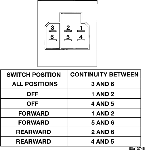
(4) Check the power window switch continuity in each position, as shown in the chart (Fig. 1). If OK, see the Power Window Motor diagnosis in this group. If not OK, replace the faulty switch.
POWER WINDOW MOTOR
For circuit descriptions and diagrams, refer to 8W-60 - Power Windows in Group 8W - Wiring Diagrams. Before you proceed with this diagnosis, confirm proper switch operation. See the Door Module and/or the Power Window Switch diagnosis in this group.
(1) Remove the door trim panel as described in Door Module (front door) or Power Window Switch (rear door) in this group.
(2) Unplug the power window motor wire harness connector. Apply 12 volts across the motor terminals to check its operation in one direction. Reverse the connections across the motor terminals to check the operation in the other direction. Remember, if the window is in the full up or full down position, the motor will not operate in that direction by design. If OK, repair the circuits from the motor to the door module or the switch as required. If not OK, replace the faulty motor.
(3) If the motor operates in both directions, check the operation of the window glass and lift mechanism through its complete up and down travel. There should be no binding or sticking of the window glass or lift mechanism through the entire travel range. If not OK, refer to Group 23 - Body to check the window glass, tracks, and regulator for sticking, binding, or improper adjustment.
REMOVAL AND INSTALLATION
DOOR MODULE
Before replacing the door module, use a DRB scan tool to determine the current settings for the door module programmable features. These settings should be duplicated in the replacement door module using the DRB scan tool, before returning the vehicle to service.
(1) Disconnect and isolate the battery negative cable.
(2) Remove the bezel near the inside door latch release handle by inserting a straight-bladed screwdriver in the notched end of the bezel and prying gently upwards.
(3) Remove the screw located beneath the bezel that secures the front door trim panel to the inner door panel (Fig. 2).
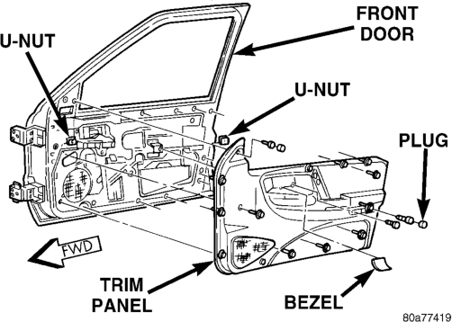
(4) Remove the trim cap and screw near the rear of the front door armrest.
(5) Remove the trim cap and screw at the upper front corner of the front door trim panel.
(6) Remove the screw located above the front door speaker grille on the front door trim panel.
(7) Using a trim stick or another suitable wide flat-bladed tool, gently pry the front door trim panel away from the door around the perimeter to release the trim panel retainers.
NOTE: To aid in the removal of the trim panel, start at the bottom of the panel.
(8) Pull the front door trim panel away from the inner door panel far enough to access and unplug the wire harness connectors from the door module and, if the vehicle is so equipped, from the front door courtesy lamp.
(9) Remove the five screws that secure the door module to the back of the front door trim panel (Fig. 3).
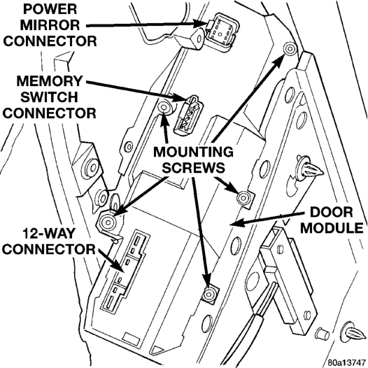
(10) Remove the door module from the trim panel. (11) Reverse the removal procedures to install. Tighten the mounting screws to 2.2 N·m (20 in. lbs.).
NOTE: If a new door module is installed, the programmable features must be enabled and/or disabled to the customer's preferred settings. Use a DRB scan tool and the proper Diagnostic Procedures manual to perform these operations.
POWER WINDOW SWITCH
(1) Disconnect and isolate the battery negative cable.
(2) Remove the bezel near the inside door latch release handle by inserting a straight-bladed screwdriver in the notched end of the bezel and prying gently upwards.
(3) Remove the screw located beneath the bezel that secures the rear door trim panel to the inner door panel (Fig. 4).
(4) Remove the trim cap and screw near the rear of the rear door armrest.
(5) Using a trim stick or another suitable wide flat-bladed tool, gently pry the rear door trim panel
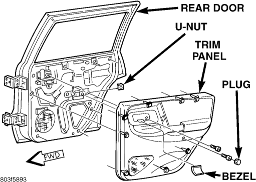
away from the door around the perimeter to release the trim panel retainers.
NOTE: To aid in the removal of the trim panel, start at the bottom of the panel.
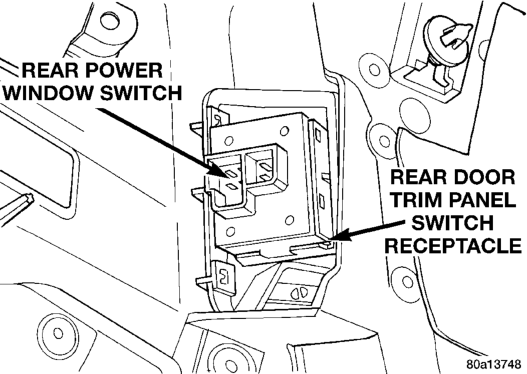
(6) Pull the rear door trim panel away from the inner door panel far enough to access and unplug the wire harness connector from the power window switch.
(7) Unsnap the power window switch from the receptacle on the back side of the rear door trim panel (Fig. 5).
(8) Reverse the removal procedures to install. Tighten the trim panel mounting screws to 1.3 N·m (12 in. lbs.).
Install
POWER WINDOW MOTOR
FRONT DOOR
(1) Disconnect and isolate the battery negative cable.
(2) Remove the front door window regulator from the front door and place the unit on a work bench. See Front Door Window Regulator in Group 23 - Body for the procedures.
(3) Remove the screws that secure the power window motor to the front door window regulator.
(4) Remove the power window motor from the front door window regulator.
(5) Reverse the removal procedures to install. Tighten the power window motor mounting screws to 5 N·m (45 in. lbs.).
REAR DOOR
(1) Disconnect and isolate the battery negative cable.
(2) Remove the rear door window regulator from the rear door and place the unit on a work bench. See Rear Door Window Regulator in Group 23 - Body for the procedures.
(3) Remove the screws that secure the power window motor to the rear door window regulator.
(4) Remove the power window motor from the rear door window regulator.
(5) Reverse the removal procedures to install. Tighten the power window motor mounting screws to 5 N·m (45 in. lbs.).