Power Mirror Systems — 1998 Jeep Grand Cherokee ZJ Export Service Manual
Pages 527–533 · 7 pages · 3 words repaired
DESCRIPTION AND OPERATION
POWER MIRROR
The power mirrors are connected to battery feed at all times. Each mirror head contains two electric motors, two drive mechanisms, an electric heating element, and the mirror glass. If the vehicle is equipped with the optional memory system, each mirror head also contains both a horizontal and a vertical motor position sensor. One motor and drive controls mirror up-and-down movement, and the other controls right-and-left movement.
The power mirrors are equipped with a standard equipment electric heating grid located behind the mirror glass. This heating grid is energized or de-energized by the Driver Door Module (DDM) or Passenger Door Module (PDM) in response to messages placed on the Chrysler Collision Detection (CCD) data bus by the Body Control Module (BCM). Refer to Group 8N - Electrically Heated Systems for more information on the operation of the rear window defogger system.
An optional driver side outside electrochromic mirror is able to automatically change its reflectance level. This mirror is controlled by the circuitry of the automatic day/night inside rear view mirror. A thin layer of electrochromic material between two pieces of conductive glass make up the face of the mirror. Two photocell sensors on the inside rear view mirror are used to monitor light levels and adjust the reflectance of both the inside and driver side outside mirrors. This change in reflectance helps to reduce the glare of headlamps approaching the vehicle from the rear. Refer to the Automatic Day/Night Mirror section of this group for more information on the operation of this system.
The power mirror assembly cannot be repaired. Only the mirror glass and glass case are serviced separately. If any other component of the power mirror unit is faulty or damaged, the entire mirror head assembly must be replaced.
POWER MIRROR SWITCH
Both the right and left power outside mirrors are controlled by a single multi-function switch unit located on the driver side front door trim panel. This switch unit is integral to the Driver Door Module (DDM).
A selector switch is moved right (right mirror control), left (left mirror control), or center to turn the power outside mirror control off. Then one of four directional control buttons is depressed to control movement of the selected mirror up, down, right, or left.
The power mirror switch cannot be repaired and, if faulty or damaged, the entire DDM unit must be replaced.
DOOR MODULE
A Driver Door Module (DDM) and a Passenger Door Module (PDM) are used on this model to control and integrate many of the electronic features and functions on the vehicle. Each door module contains the power mirror control logic for the mirror on its respective door. The DDM also houses the power mirror switch.
The DDM and PDM communicate with each other, and with other vehicle modules on the Chrysler Collision Detection (CCD) data bus network. The CCD data bus network allows the sharing of sensor information. This helps to reduce wire harness complexity, internal controller hardware, and component sensor current loads. At the same time, this system provides increased reliability, enhanced diagnostics, and allows the addition of many new feature capabilities.
Each door module controls the positioning of its respective outside mirror through hard-wired outputs to that mirror. When the power mirror switch on the DDM is used to position the passenger side outside mirror, the DDM sends mirror positioning messages to the PDM on the CCD data bus. The PDM then moves the passenger side mirror accordingly.
Both the PDM and DDM respond to the defogger switch status messages sent by the Body Control Module (BCM) on the CCD data bus to control the heater elements of their respective mirrors. Refer to Group 8N - Electrically Heated Systems for more information on this feature. On models equipped with the optional memory system, each door module also receives a hard-wired input from the two power mirror motor position sensors integral to the mirror. The door module then stores the Driver 1 and 2 mirror position information for its respective mirror. When the DDM receives a Driver 1 or 2 signal from the memory switch on the driver side front door trim panel or from the Remote Keyless Entry (RKE) receiver in the PDM, the DDM positions the driver side mirror and sends a memory recall message back to the PDM on the CCD data bus to position the passenger side mirror.
For diagnosis of the DDM, PDM, or the CCD data bus network, a DRB scan tool and the proper Diagnostic Procedures manual are recommended. The DDM and the PDM cannot be repaired and, if damaged or faulty, they must be replaced.
DIAGNOSIS AND TESTING
POWER MIRROR SYSTEM
If only one power mirror is inoperative, or partially inoperative, see the tests under Power Mirror in this group. If both power mirrors are inoperative, proceed as follows. For circuit descriptions and diagrams, refer to 8W-62 - Power Mirrors in Group 8W - Wiring Diagrams.
NOTE: The following tests may not prove conclusive in the diagnosis of this system. The most reliable, efficient, and accurate means to diagnose this system involves the use of a DRB scan tool and the proper Diagnostic Procedures manual.
(1) Check the circuit breaker in the junction block. If OK, go to Step 2. If not OK, replace the faulty circuit breaker.
(2) Check the fuse in the Power Distribution Center (PDC). If OK, go to Step 3. If not OK, repair the shorted circuit or component as required and replace the faulty fuse.
(3) Disconnect and isolate the battery negative cable. Remove the driver side front door trim panel and check the 12-way Driver Door Module (DDM) wire harness connector to see that it is fully seated in the door module receptacle. If OK, go to Step 4. If not OK, install the wire harness connector properly.
(4) Unplug the 12-way wire harness connector from the DDM. Check for continuity between the ground circuit cavity of the DDM wire harness connector and a good ground. There should be continuity. If OK, go to Step 5. If not OK, repair the open circuit as required.
(5) Connect the battery negative cable. Check for battery voltage at the fused B(+) circuit cavity of the DDM wire harness connector. If OK, use a DRB scan tool and the proper Diagnostic Procedures manual to test both door modules and the CCD data bus. If not OK, repair the open circuit as required.
POWER MIRROR
If both power mirrors are inoperative, see the tests under Power Mirror System in this group. If only one power mirror is inoperative, or partially inoperative, refer to the symptom diagnosis as follows. For circuit descriptions and diagrams, refer to 8W-62 - Power Mirrors in Group 8W - Wiring Diagrams.
LIMITED OR NO MIRROR MOVEMENT
(1) Disconnect and isolate the battery negative cable. Remove the front door trim panel on the side of the inoperative mirror.
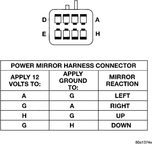
(2) Unplug the mirror wire harness connector from the door module. Using two jumper wires, test the mirror as shown in the Mirror Test chart (Fig. 1). If the mirror tests OK, use a DRB scan tool and the proper Diagnostic Procedures manual to test the door module and the CCD data bus. If the mirror does not test OK, replace the faulty mirror.
NO MIRROR HEAT
If both mirror heaters are inoperative, refer to Group 8N - Electrically Heated Systems to test the Rear Defogger System.
(1) Disconnect and isolate the battery negative cable. Remove the front door trim panel on the side of the inoperative mirror.
(2) Unplug the mirror wire harness connector from the door module. Check for continuity between the heater switched ground circuit cavity and the heater 12V supply circuit cavity of the mirror wire harness connector. There should be continuity. If OK, use a DRB scan tool and the proper Diagnostic Procedures manual to test the door module and the CCD data bus. If not OK, replace the faulty mirror.
NO MIRROR DIMMING (Driver Side Only)
(1) Test the operation of the Automatic Day/Night Mirror as described in this group. If OK, go to Step 2. If not OK, repair the automatic day/night mirror unit as necessary before you proceed.
(2) Disconnect and isolate the battery negative cable. Remove the driver side front door trim panel.
(3) Unplug the 2-way electrochromic mirror wire harness connector from the driver side outside power mirror. Connect a voltmeter to the door half of the electrochromic mirror wire harness connector. Perform the automatic day/night mirror test as described in this group, while observing the voltmeter. A voltmeter reading of 1.45 6 0.05 volts indicates a proper dimming signal is being received at the electrochromic mirror wire harness connector. If OK, replace the faulty power mirror. If not OK, repair the circuits to the automatic day/night mirror as required.
NO MIRROR MEMORY
For diagnosis of the memory system, the use of a DRB scan tool and the proper Diagnostic Procedures manual are recommended.
REMOVAL AND INSTALLATION
DOOR MODULE
Before replacing the door module, use a DRB scan tool to determine the current settings for the door module programmable features. These settings should be duplicated in the replacement door module using the DRB scan tool, before returning the vehicle to service.
(1) Disconnect and isolate the battery negative cable.
(2) Remove the bezel near the inside door latch release handle by inserting a straight-bladed screwdriver in the notched end of the bezel and prying gently upwards.
(3) Remove the screw located beneath the bezel that secures the front door trim panel to the inner door panel (Fig. 2).
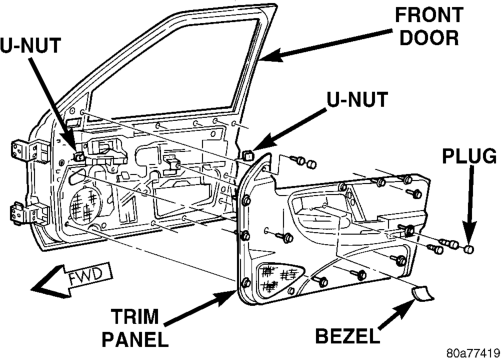
(4) Remove the trim cap and screw near the rear of the front door armrest.
(5) Remove the trim cap and screw at the upper front corner of the front door trim panel.
(6) Remove the screw located above the front door speaker grille on the front door trim panel.
(7) Using a trim stick or another suitable wide flat-bladed tool, gently pry the front door trim panel away from the door around the perimeter to release the trim panel retainers.
NOTE: To aid in the removal of the trim panel, start at the bottom of the panel.
(8) Pull the front door trim panel away from the inner door panel far enough to access and unplug the wire harness connectors from the door module and, if the vehicle is so equipped, from the front door courtesy lamp.
(9) Remove the five screws that secure the door module to the back of the front door trim panel (Fig. 3).
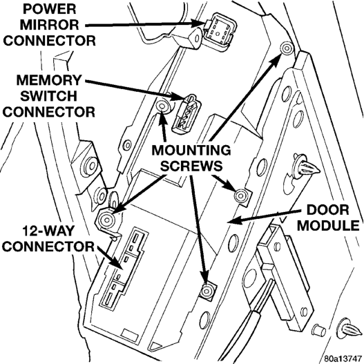
(10) Remove the door module from the trim panel. (11) Reverse the removal procedures to install. Tighten the mounting screws to 2.2 N·m (20 in. lbs.).
NOTE: If a new door module is installed, the programmable features must be enabled and/or disabled to the customer's preferred settings. Use a DRB scan tool and the proper Diagnostic Procedures manual to perform these operations.
POWER MIRROR
(1) Disconnect and isolate the battery negative cable.
(2) Remove the front door trim panel. See Door Module in this group for the procedures.
(3) Unplug the electrochromic mirror wire harness connector, if the vehicle is so equipped.
(4) Disconnect the power mirror wire harness retainers from the inner door panel.
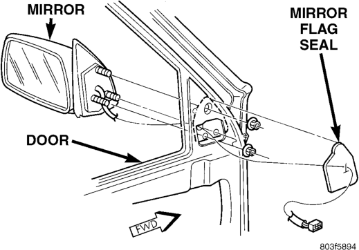
(5) Remove the mirror flag seal from the door panel (Fig. 4).
(6) Remove the three nuts that secure the mirror to the door.
(7) Remove the mirror from the door. (8) Reverse the removal procedures to install. Tighten the mirror mounting nuts to 7.4 N·m (65 in. lbs.).
GENERAL INFORMATION
INTRODUCTION . . . . . . . . . . . . . . . . . . . . . . . . . 6 DESCRIPTION AND OPERATION
AUTOMATIC DAY/NIGHT MIRROR . . . . . . . . . . . . 6
GENERAL INFORMATION
INTRODUCTION
An automatic dimming inside day/night rear view mirror and an automatic dimming driver side outside rear view mirror are available factory-installed options on this model. Following is a general description of this optional equipment. Refer to 8W-44 - Interior Lighting and 8W-62 - Power Mirrors in Group 8W - Wiring Diagrams for complete circuit descriptions and diagrams.
DESCRIPTION AND OPERATION
AUTOMATIC DAY/NIGHT MIRROR
The automatic day/night mirror is able to automatically change its reflectance. A thin layer of electrochromic material between two pieces of conductive glass make up the face of the mirror. Two photocell sensors are used to monitor light levels and adjust the reflectance of the mirror to reduce the glare of headlamps approaching the vehicle from the rear.
The ambient photocell sensor faces forward, to detect the outside light levels. The headlamp sensor faces rearward, to detect the light level received at the rear window side of the mirror. When the difference between the two light levels becomes too great (the light level received at the rear of the mirror is much higher than that at the front of the mirror), the mirror begins to darken.
The mirror switch allows the driver a manual control of whether the automatic dimming feature is operational. When On is selected, the mirror switch is lighted by an integral Light-Emitting Diode (LED). The automatic dimming feature will only operate when the ignition switch is in the On position. The mirror also senses the backup lamp circuit, and will automatically disable its self-dimming feature when-
AUTOMATIC DAY/NIGHT MIRROR
INDEX
page page
DIAGNOSIS AND TESTING
AUTOMATIC DAY/NIGHT MIRROR . . . . . . . . . . . . 6 REMOVAL AND INSTALLATION
AUTOMATIC DAY/NIGHT MIRROR . . . . . . . . . . . . 7 ever the transmission gear selector is in the Reverse position.
On models with an optional electrochromic driver side outside rear view mirror, the signal to control the dimming of that mirror is generated by the automatic day/night inside rear view mirror circuitry. That signal is then delivered to the driver side outside rear view mirror on a hard-wired circuit.
The automatic day/night mirror cannot be repaired. If faulty or damaged, the entire inside rear view mirror assembly must be replaced.
DIAGNOSIS AND TESTING
AUTOMATIC DAY/NIGHT MIRROR
For circuit descriptions and diagrams, refer to 8W-44 - Interior Lighting or 8W-62 Power Mirrors in Group 8W - Wiring Diagrams.
(1) Check the fuse in the junction block. If OK, go to Step 2. If not OK, repair the shorted circuit or component as required and replace the faulty fuse.
(2) Turn the ignition switch to the On position. Check for battery voltage at the fuse in the junction block. If OK, go to Step 3. If not OK, repair the open circuit to the ignition switch as required.
(3) Unplug the wire harness connector from the automatic day/night mirror (Fig. 1). Check for battery voltage at the fused ignition switch output circuit cavity of the automatic day/night mirror wire harness connector. If OK, go to Step 4. If not OK, repair the open circuit to the junction block as required.
(4) Turn the ignition switch to the Off position. Check for continuity between the ground circuit cavity of the automatic day/night mirror wire harness connector and a good ground. There should be continuity. If OK, go to Step 5. If not OK, repair the circuit to ground as required.
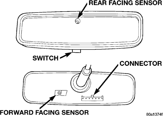
(5) Turn the ignition switch to the On position. Set the parking brake. Place the transmission gear selector lever in the Reverse position. Check for battery voltage at the backup lamp switch output circuit cavity of the automatic day/night mirror wire harness connector. If OK, reinstall the automatic day/night mirror wire harness connector and go to Step 6. If not OK, repair the open circuit as required.
(6) Place the transmission gear selector lever in the Neutral position. Place the automatic day/night mirror switch in the On (LED in the switch is lighted) position. Cover the forward facing ambient photocell sensor to keep out any ambient light.
NOTE: The ambient photocell sensor must be covered completely, so that no light reaches the sensor. Use a finger pressed tightly against the sensor, or cover the sensor completely with electrical tape.
(7) Shine a light into the rearward facing headlamp photocell sensor. The automatic day/night mirror should darken. If OK, go to Step 8. If not OK, replace the faulty mirror unit.
(8) With the mirror darkened, place the transmission gear selector lever in the Reverse position. The automatic day/night mirror should return to its normal reflectance. If not OK, replace the faulty mirror unit.
REMOVAL AND INSTALLATION
AUTOMATIC DAY/NIGHT MIRROR
(1) Disconnect and isolate the battery negative cable.
(2) If the vehicle is so equipped, remove the automatic day/night mirror wire harness cover by grasping the lower portion of the cover and sliding it into the upper portion and off of the mirror base (Fig. 2).
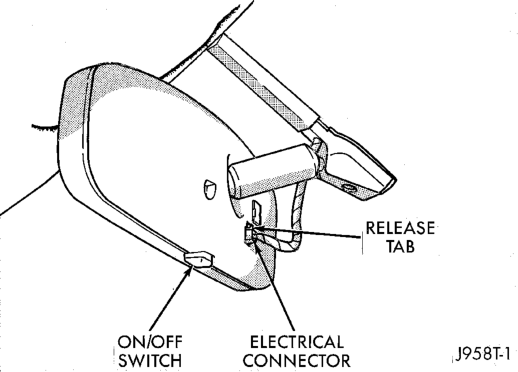
Typical
(3) Unplug the wire harness connector from the automatic day/night mirror.
(4) Remove the set screw that secures the automatic day/night mirror to the windshield support button.
(5) Push the automatic day/night mirror upwards far enough to clear the support button and remove the mirror from the windshield support button.
(6) Reverse the removal procedures to install. Tighten the mounting screw to 1.7 N·m (15 in. lbs.).