Overhead Console Systems — 1998 Jeep Grand Cherokee ZJ Export Service Manual
Pages 539–547 · 9 pages · 3 words repaired
trip computer. The compass flux-gate unit is integral to the trip computer, compass, and thermometer display module unit. Data input for all other trip computer functions is received through CCD data bus messages. The trip computer uses its internal programming and all of these inputs to calculate and display the requested data. If the data displayed is incorrect, perform the self-diagnostic tests as described in this group. If these tests prove inconclusive, the use of a DRB scan tool and the proper Diagnostic Procedures manual are recommended for further testing of the trip computer and the CCD data bus.
The trip computer, compass, and thermometer display module cannot be repaired, and are only available for service as a unit. If faulty, the complete module must be replaced. The push button (Step and U.S./Metric) switch module is serviced separately.
COMPASS
The compass will display the direction in which the vehicle is pointed using the eight major compass headings (Examples: north is N, northeast is NE). It does not display the headings in actual degrees.
The self-calibrating compass unit requires no adjusting in normal use. The only calibration that may prove necessary is to drive the vehicle in three complete circles, on level ground, in not less than 48 seconds. This will reorient the compass unit to its vehicle.
The compass unit also will compensate for magnetism the body of the vehicle may acquire during normal use. However, avoid placing anything magnetic directly on the roof of the vehicle. Magnetic mounts for an antenna, a repair order hat, or a funeral procession flag can exceed the compensating ability of the compass unit if placed on the roof panel. Magnetic bit drivers used on the fasteners that hold the assembly to the roof header can also affect compass operation. If the vehicle roof should become magnetized, the demagnetizing and calibration procedures found in this group may be required to restore proper compass operation.
The compass, trip computer, and thermometer display module cannot be repaired, and are only available for service as a unit. If faulty, the complete module must be replaced. The push button (Step and U.S./Metric) switch module is serviced separately.
THERMOMETER
The thermometer displays the outside ambient temperature. The temperature display can be changed from Fahrenheit to Celsius using the U.S./ Metric button, located just rearward of the display module. The displayed temperature is not an instant reading of conditions, but an average temperature. It may take the thermometer display several minutes to respond to a major temperature change, such as driving out of a heated garage into winter temperatures.
When the ignition switch is turned to the Off position, the last displayed temperature reading stays in the thermometer unit memory. When the ignition switch is turned to the On position again, the thermometer will display the memory temperature for one minute; then update the display to the current average temperature reading within five minutes.
The thermometer function is supported by an ambient temperature sensor. The sensor is mounted outside the passenger compartment near the front and center of the vehicle and is hard-wired to the Body Control Module (BCM). The BCM sends a temperature status message to the overhead console over the Chrysler Collision Detection (CCD) data bus network. The ambient temperature sensor is available as a separate service item.
The thermometer, compass, and trip computer display module cannot be repaired, and are only available for service as a unit. If faulty, the complete module must be replaced. The push button (Step and U.S./Metric) switch module and ambient temperature sensor are serviced separately.
READING AND COURTESY LAMP
All reading and courtesy lamps located in the overhead console are activated by the door ajar switches. When the doors are closed, the lamps can be individually activated by depressing the corresponding lens.
When a door is open, depressing the lamp lens switches will not turn the lamps off. Refer to Group 8L - Lamps, for diagnosis of the reading and courtesy lamps.
The reading and courtesy lamp lens, and bulbs are available for service replacement. The reading and courtesy lamp holders and switches are only available as part of the overhead console wire harness. If any reading lamp switch is faulty or damaged, the wire harness and all four switches must be replaced.
GARAGE DOOR OPENER STORAGE BIN
A compartment in the long-type overhead console is designed to hold most garage door opener remote control transmitters. The transmitter is mounted within the compartment with an adhesive-backed hook and loop fastener patch.
With the transmitter mounted in the storage bin, adapter pegs located on the front of the storage bin door are selected and mounted on a post near the center of the storage bin door. The peg(s) selected and/or the post must be long enough to depress the button of the transmitter, when the garage door opener storage bin door is depressed. The pegs may be stacked, if necessary. Refer to the owner's manual in the vehicle glove box for more information. A transmitter mounting kit including the adhesivebacked hook and loop fastener material and a selection of pegs is available for service. The garage door opener storage bin door assembly is also available for service replacement.
SUNGLASSES STORAGE BIN
A sunglasses storage bin is included in the longtype overhead console. The interior of the bin is lined with a foam rubber padding material to protect the sunglasses from being scratched. This bin features a push/push-type latching mechanism, and a viscous dampening system for a fluid opening action.
The sunglasses storage bin door, latch, viscous damper, hinge spring and housing are available for service only as a complete module. If any part of this unit is faulty or damaged, the entire module must be replaced.
DIAGNOSIS AND TESTING
TRIP COMPUTER, COMPASS, AND THERMOMETER DISPLAY MODULE
If the problem with the trip computer, compass, and thermometer display module is an inaccurate or scrambled display, use the Self-Diagnostic Test procedures. If the problem is incorrect display lighting levels, use a DRB scan tool and the proper Diagnostic Procedures manual to test for the correct dimming message inputs being received from the Body Control Module (BCM) over the Chrysler Collision Detection (CCD) data bus. If the problem is a no-display condition, use the following procedures. For circuit descriptions and diagrams, refer to 8W-49 - Overhead Console in Group 8W - Wiring Diagrams.
(1) Check the fuses in the junction block. If OK, go to Step 2. If not OK, repair the shorted circuit or component as required and replace the faulty fuse(s).
(2) Turn the ignition switch to the On position. Check for battery voltage at the fused ignition switch output fuse in the junction block. If OK, go to Step 3. If not OK, repair the open circuit to the ignition switch as required.
(3) Turn the ignition switch to the Off position. Disconnect and isolate the battery negative cable. Remove the overhead console as described in this group. Check for continuity between the ground circuit cavity of the overhead console wire harness connector and a good ground. There should be continuity. If OK, go to Step 4. If not OK, repair the open circuit to ground as required.
(4) Connect the battery negative cable. Check for battery voltage at the fused B(+) circuit cavity of the overhead console wire harness connector. If OK, go to
Step 5. If not OK, repair the open circuit to the junction block as required.
(5) Turn the ignition switch to the On position. Check for battery voltage at the fused ignition switch output circuit cavity of the overhead console wire harness connector. If OK, proceed to the Self-Diagnostic Test in this group for further diagnosis of the module and the CCD data bus. If not OK, repair the open circuit to the junction block as required.
SELF-DIAGNOSTIC TEST
A self-diagnostic test is used to determine that the trip computer, compass, thermometer, and all of the display module segments are operating properly electrically. Initiate the self-diagnostic test as follows:
(1) With the ignition switch in the Off position, simultaneously press and hold the Step button and the U.S./Metric button.
(2) Turn the ignition switch to the On position. (3) Continue to hold both buttons until the display module performs a display segment test. In this test, all of the vacuum fluorescent display segments are lighted. This test will:
a. Verify that all display segments are functional b. Check the internal circuitry of the module c. Check that all of the CCD data bus messages needed are being received.
(4) Respond to the respective test results as follows. If all tests are passed, the module will automatically return to normal operation. d. In the display segment test, if any segment should fail to light the unit is faulty and must be replaced.
e. If the internal circuitry test is failed, the module will display “FAIL”. If “FAIL” is displayed, the unit is faulty and must be replaced.
f. If the CCD data bus message test is failed, the module will display “CCD”. If “CCD” is displayed, the use of a DRB scan tool and the proper Diagnostic Procedures manual are required for further diagnosis.
(5) Momentarily depress and release either button one time to exit the self-diagnostic test mode and return the trip computer, compass, and thermometer display module to normal operation.
NOTE: If the compass functions, but accuracy is suspect, it may be necessary to perform a variation adjustment. This procedure allows the compass unit to accommodate variations in the earth's magnetic field strength, based on geographic location. See the Compass Variation Adjustment procedures, in this group.
NOTE: If the compass reading has blanked out, and only “CAL” appears in the display module, demagnetizing may be necessary to remove excessive residual magnetic fields from the vehicle. See the Compass Demagnetizing procedure, in this group.
THERMOMETER
The thermometer function is supported by a ambient temperature sensor, a wiring circuit, the Body Control Module (BCM), the Chrysler Collision Detection (CCD) data bus, and a portion of the overhead console trip computer, compass, and thermometer display module display. The sensor is mounted outside the passenger compartment near the front and center of the vehicle.
If any portion of the ambient temperature sensor circuit fails, the thermometer display will self-diagnose the circuit. An “SC” (short circuit) will appear in the display in place of the temperature, when the sensor is exposed to temperatures above 55° C (131° F), or if the sensor circuit is shorted. An “OC” (open circuit) will appear in the display in place of the temperature, when the sensor is exposed to temperatures below -40° C (-40° F), or if the sensor circuit is open.
The ambient temperature sensor circuit can also be diagnosed using the following Sensor Test, and Sensor Circuit Test. If the temperature sensor and circuit are confirmed to be OK, but the temperature display is inoperative or incorrect, see the Trip Computer, Compass, and Thermometer Display Module diagnosis in this group. For circuit descriptions and diagrams, refer to 8W-45 - Body Control Module and 8W-49 - Overhead Console in Group 8W - Wiring Diagrams.
SENSOR TEST
(1) Turn the ignition switch to the Off position. Disconnect and isolate the battery negative cable. Unplug the temperature sensor wire harness connector.
(2) Measure the resistance of the temperature sensor. At -40° C (-40° F), the sensor resistance is 336 kilohms. At 55° C (140° F), the sensor resistance is 2.488 kilohms. The sensor resistance should read between these two values. If OK, go to the Sensor Circuit Test. If not OK, replace the faulty sensor.
SENSOR CIRCUIT TEST
(1) Turn the ignition switch to the Off position. Disconnect and isolate the battery negative cable. Unplug the ambient temperature sensor wire harness connector and the black 24-way Body Control Module (BCM) wire harness connector.
(2) Connect a jumper wire between the two terminals in the body half of the sensor wire harness connector.
(3) Check for continuity between the sensor return circuit and the ambient temperature sensor signal circuit cavities of the black 24-way BCM wire harness connector. There should be continuity. If OK, go to Step 4. If not OK, repair the open circuit as required.
(4) Remove the jumper wire from the ambient temperature sensor wire harness connector. Check for continuity between the sensor return circuit cavity of the black 24-way BCM wire harness connector and a good ground. There should be no continuity. If OK, go to Step 5. If not OK, repair the short circuit as required.
(5) Check for continuity between the ambient temperature sensor signal circuit cavity of the black 24-way BCM wire harness connector and a good ground. There should be no continuity. If OK, see the Trip Computer, Compass, and Thermometer Display Module diagnosis in this group. If not OK, repair the short circuit as required.
SERVICE PROCEDURES
COMPASS VARIATION ADJUSTMENT
Variance is the difference between magnetic north and geographic north. In some geographic locations, the difference between magnetic and geographic north is great enough to cause the compass to give false readings. If this problem occurs, the compass variance must be set.
To set the compass variance: (1) Using the Variance Settings map, find your geographic location and note the zone number (Fig. 1).
(2) Turn the ignition switch to the On position. If the compass/temperature data is not currently being displayed, momentarily depress and release the Step button to step through the display options until you have reached the compass/temperature display.
(3) Depress both the U.S./Metric, and the Step buttons. Hold the buttons down until “VAR” appears in the display. This takes about five seconds.
(4) Release both of the buttons. The current variance zone number setting will appear in the display.
(5) Press and release the U.S./Metric button to step through the zone numbers, until the zone number for your geographic location appears in the display.
(6) Press the Step button to enter this zone number into the compass unit memory.
(7) Confirm that the correct directions are now indicated by the compass.

COMPASS CALIBRATION
CAUTION: Do not place any external magnets, such as magnetic roof mount antennas, in the vicinity of the compass. Do not use magnetic tools when servicing the overhead console.
The electronic compass unit features a self-calibrating design, which simplifies the calibration procedure. This feature automatically updates the compass calibration while the vehicle is being driven. This allows the compass unit to compensate for small changes in the residual magnetism that the vehicle may acquire during normal use. Do not attempt to calibrate the compass near large metal objects such as other vehicles, large buildings, or bridges.
NOTE: Whenever the compass is calibrated manually, the variation number must also be reset. See the Compass Variation Adjustment procedure, in this group.
Calibrate the compass manually as follows: (1) Start the engine. If the compass/temperature data is not currently being displayed, momentarily depress and release the Step button to step through the display options until you have reached the compass/temperature display.
(2) Depress both the U.S./Metric, and the Step buttons. Hold the buttons down until “CAL” appears in the display. This takes about ten seconds, and appears about five seconds after “VAR” is displayed.
(3) Release both of the buttons. (4) Drive the vehicle on a level surface, away from large metal objects, through three or more complete circles in not less than 48 seconds. The “CAL” message will disappear from the display to indicate that the compass is now calibrated.
NOTE: If the “CAL” message remains in the display, either there is excessive magnetism near the compass, or the unit is faulty. Repeat the demagnetizing and calibration procedures at least one more time.
NOTE: If the wrong direction is still indicated in the compass display, the area selected for calibration may be too close to a strong magnetic field. Repeat the calibration procedure in another location.
COMPASS DEMAGNETIZING
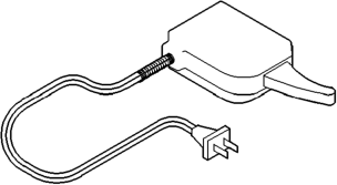
A degaussing tool (Special Tool 6029) is used to demagnetize, or degauss, the overhead console forward mounting screw(s) and the roof panel. Equivalent units must be rated as continuous duty for 110/ 115 volts and 60 Hz. They must also have a field strength of over 350 gauss at 7 millimeters (0.25 inch) beyond the tip of the probe.
To demagnetize the roof panel and the overhead console forward mounting screw(s), proceed as follows:
(1) Be certain the ignition switch is in the Off position, before you begin the demagnetizing procedure.
(2) Plug in the degaussing tool, while keeping the tool at least 61 centimeters (2 feet) away from the compass unit.
(3) Slowly approach the head of the overhead console forward mounting screw with the degaussing tool plugged in.
(4) Contact the head of each screw with the plastic coated tip of the degaussing tool for about two seconds.
(5) With the degaussing tool still energized, slowly back it away from the screw. When the tip of the tool is at least 61 centimeters (2 feet) from the screw head, unplug the tool.
(6) Place a piece of paper approximately 22 by 28 centimeters (8.5 by 11 inches), oriented on the vehicle lengthwise from front to rear, on the center line of the roof at the windshield header (Fig. 2). The purpose of the paper is to protect the roof panel from scratches, and to define the area to be demagnetized.
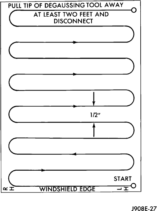
(7) Plug in the degaussing tool, while keeping the tool at least 61 centimeters (2 feet) away from the compass unit.
(8) Slowly approach the center line of the roof panel at the windshield header, with the degaussing tool plugged in.
(9) Contact the roof panel with the plastic coated tip of the degaussing tool. Be sure that the template is in place to avoid scratching the roof panel. Using a slow, back-and-forth sweeping motion, and allowing 13 millimeters (0.50 inch) between passes, move the tool at least 11 centimeters (4 inches) to each side of the roof center line, and 28 centimeters (11 inches) back from the windshield header.
(10) With the degaussing tool still energized, slowly back it away from the roof panel. When the tip of the tool is at least 61 centimeters (2 feet) from the roof panel, unplug the tool.
(11) Calibrate the compass and adjust the compass variance as described in this group.
REMOVAL AND INSTALLATION
OVERHEAD CONSOLE
LONG-TYPE
(1) Disconnect and isolate the battery negative cable.
(2) Remove the single screw located forward of the display module that secures the overhead console to the upper windshield opening reinforcement (Fig. 3).
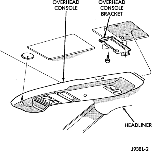
Type
(3) To release the overhead console from the rear mounting bracket, slide the console forward until the rear of the console separates from the bracket.
(4) Lower the overhead console far enough to access the two wire harness connectors.
(5) Unplug one wire harness connector near the push button module towards the front of the overhead console.
(6) Unplug one wire harness connector from the reading and courtesy lamp module near the rear of the overhead console.
(7) Remove the overhead console from the vehicle. (8) Reverse the removal procedures to install. Tighten the overhead console mounting screw to 2.2 N·m (20 in. lbs.).
SHORT-TYPE
(1) Disconnect and isolate the battery negative cable.
(2) Remove the single screw located forward of the display module that secures the overhead console to the upper windshield opening reinforcement (Fig. 4).
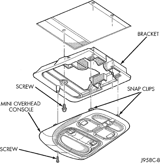
Type
(3) Using a trim stick or another suitable wide flat-bladed tool, gently pry downwards at the rear edge of the overhead console housing to release the two snap clip retainers that secure the console to the mounting bracket.
(4) Lower the overhead console far enough to access the two wire harness connectors.
(5) Unplug one wire harness connector from the trip computer, compass, and thermometer display module.
(6) Unplug one wire harness connector from the power sunroof switch.
(7) Remove the overhead console from the vehicle. (8) Reverse the removal procedures to install. Tighten the overhead console mounting screw to 2.2 N·m (20 in. lbs.).
TRIP COMPUTER, COMPASS, AND THERMOMETER DISPLAY MODULE
(1) Remove the overhead console from the vehicle. See Overhead Console in this group for the procedures.
(2) Remove the two screws that secure the forward end of the trip computer, compass, and thermometer display module to the overhead console housing (Fig. 5).
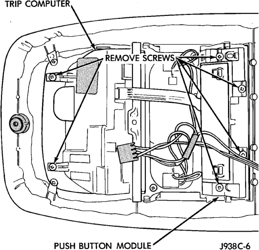
Display Module Remove/install - Typical
(3) Gently flex the sides of the overhead console housing as required to release the trip computer, compass, and thermometer display module mounting pins.
(4) Pull the trip computer, compass, and thermometer display module away from the overhead console housing far enough to access the two wire harness connectors.
(5) Unplug the overhead console and push button module wire harness connectors from the trip computer, compass, and thermometer display module.
(6) Remove the trip computer, compass, and thermometer display module from the overhead console housing.
(7) Reverse the removal procedures to install. Tighten the mounting screws to 2.2 N·m (20 in. lbs.).
PUSH BUTTON MODULE
(1) Remove the overhead console from the vehicle. See Overhead Console in this group for the procedures.
(2) Unplug the push button module wire harness connector from the trip computer, compass, and thermometer display module.
(3) Remove the four screws (long-type console) or two screws (short-type console) that secure the push button module to the overhead console housing.
(4) Remove the push button module from the overhead console.
(5) Reverse the removal procedures to install. Tighten the mounting screws to 2.2 N·m (20 in. lbs.).
READING AND COURTESY LAMP BULB
(1) Disconnect and isolate the battery negative cable.
(2) Insert a long, narrow, flat-bladed tool in the notch on the edge of the reading and courtesy lamp lens.
(3) Gently pry the lens downward from the overhead console housing and pivot the lens down. It may be necessary to move the tool along the edge of the lens to free the lens from the console housing.
(4) Unsnap the bulb from the bulb holders by pulling the bulb gently downwards. (5) Install a new bulb by aligning its base with the bulb holders and pushing the bulb firmly into place.
(6) Pivot the lens back up into position and press upward firmly until it snaps into place.
(7) Connect the battery negative cable. (8) Test the lamp by depressing the lens to check for proper lamp switching and lighting.
GARAGE DOOR OPENER STORAGE BIN DOOR
(1) Open the garage door opener storage bin door. (2) Using a trim stick or another suitable wide flat-bladed tool, gently pry between the door pivot pin and the pivot hole on one side of the overhead console housing until the pivot pin clears the pivot hole.
(3) Use a gentle twisting action to remove the garage door opener storage bin door from the overhead console housing.
(4) To install, insert the pivot pin on one side of the door into the pivot hole in the overhead console housing. Gently depress the pivot pin tab on the other side of the door until it clears the side of the garage door opener storage bin opening and push the door into the opening. Guide the door into the opening so that the pivot pin snaps into the pivot hole.
SUNGLASSES STORAGE BIN
The sunglasses storage bin door and bin, housing, damper, spring and latch are serviced only as a unit. Remove the sunglasses storage bin module from the overhead console as follows:
(1) Remove the overhead console from the vehicle. See Overhead Console in this group for the procedures.
(2) Disengage the overhead console courtesy lamp wire harness from the retainers molded into the sunglasses storage bin housing.
(3) Remove the screws that secure the sunglasses storage bin module to the overhead console housing.
(4) Remove the sunglasses storage bin module from the overhead console.
(5) Reverse the removal procedures to install. Tighten the mounting screws to 2.2 N·m (20 in. lbs.).
AMBIENT TEMPERATURE SENSOR
(1) Disconnect and isolate the battery negative cable.
(2) Remove the radiator grille from the vehicle. Refer to Group 23 - Body for the procedures.
(3) Locate the ambient temperature sensor, on the radiator support behind the grille (Fig. 6).
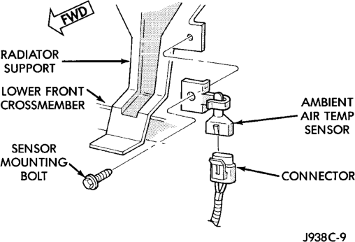
(4) Unplug the ambient temperature sensor wire harness connector.
(5) Remove the screw that secures the ambient temperature sensor to the radiator support.
(6) Remove the ambient temperature sensor from the vehicle.
(7) Reverse the removal procedures to install. Tighten the ambient temperature sensor mounting screw to 2.2 N·m (20 in. lbs.).
SPECIAL TOOLS
COMPASS