Introduction — 1998 Jeep Grand Cherokee ZJ Export Service Manual
Pages 2–12 · 11 pages · 1 words repaired
IN
Introduction

Introduction
0
Lubrication and Maintenance
0a
Lubrication and Maintenance
2
Suspension
2a
Suspension
3
Differential and Driveline
5
Brakes

Cooling System
Ja
Cooling System
8A
Battery

Starting Systems

Starting Systems
8c
Charging System
8Ca
Charging System

Ignition System

Instrument Panel Systems
SEa
Instrument Panel Systems
SF
Audio Systems
8G
Horn Systems

Vehicle Speed Control System

Vehicle Speed Control System

Turn Signal and Hazard Warning Systems
8K
Wipers and Washer Systems
8L
Lamps
SLa
Lamps
8M
Passive Restraint Systems

Electrically Heated Systems
Power Lock Systems
8Q
Vehicle Theft/Security Systems
8Qa
Vehicle Theft/Security Systems

Power Seat Systems
8s
Power Window Systems
8T
Power Mirror Systems

Chime/Buzzer Warning Systems
Overhead Console Systems sw
Wiring Diagrams

Engine
Engine
11
Exhaust System and Intake Manifold
11a
Exhaust System and Intake Manifold
13
Frame and Bumpers
14
Fuel System
14a
Fuel System - 2.5L Diesel Engine
19
Steering
19a
Steering
21
Transmission and Transfer Case
21a
Transmission and Transfer Case
22
Tires and Wheels
23
Body
24
Heating and Air Conditioning
24a
Heating and Air Conditioning
25
Emission Control Systems
25a
Emission Control System
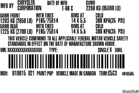
• Paint and Trim codes. • Country of origin. The label is located on the driver-side door shutface.
BODY CODE PLATE
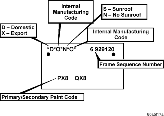
A metal Body Code plate is attached to the top, left side of the radiator reinforcement. The information listed on the plate (Fig. 2) is used for manufacturing and service purposes.
VEHICLE DIMENSIONS
The vehicle exterior and interior dimensions are listed in inches and centimeters.
EXTERIOR DIMENSIONS
Wheel Base. . . . . . . . . . . . . . . . .105.9 in. (269.1 cm.) Track: Front . . . . . . . . . . . . . . . . .58.0 in. (147.3 cm.) Track: Rear. . . . . . . . . . . . . . . . . .58.0 in. (147.3 cm.) Length . . . . . . . . . . . . . . . . . . . .176.7 in. (448.8 cm.) Width . . . . . . . . . . . . . . . . . . . . . .69.3 in. (176.0 cm.) Height . . . . . . . . . . . . . . . . . . . . .64.7 in. (164.3 cm.)
INTERIOR DIMENSIONS
Head Room-Front. . . . . . . . . . . . . .38.9 in. (98.8 cm.) Head Room-Rear . . . . . . . . . . . . . .39.0 in. (99.0 cm.) Leg-Front . . . . . . . . . . . . . . . . . . .40.9 in. (103.8 cm.) Leg-Rear . . . . . . . . . . . . . . . . . . . .35.7 in. (90.6 cm.) Shoulder-Front . . . . . . . . . . . . . . .58.3 in. (148.0 cm.) Shoulder-Rear . . . . . . . . . . . . . . .57.6 in. (146.3 cm.) Hip-Front . . . . . . . . . . . . . . . . . . .57.8 in. (146.8 cm.) Hip-Rear. . . . . . . . . . . . . . . . . . . .49.3 in. (125.2 cm.)
INTERNATIONAL VEHICLE CONTROL AND DISPLAY SYMBOLS
INTERNATIONAL VEHICLE CONTROL AND
DISPLAY SYMBOLS
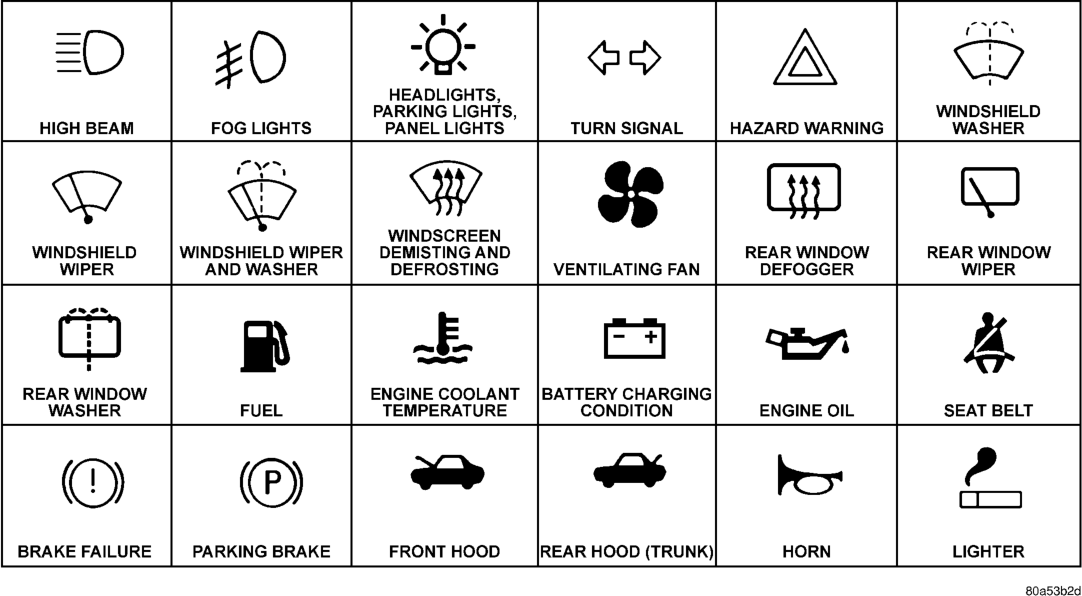
The graphic symbols illustrated in the following chart are used to identify various instrument controls. The symbols correspond to the controls and displays that are located on the instrument panel.
INTERNATIONAL CONTROL AND DISPLAY SYMBOLS
FASTENER IDENTIFICATION
FASTENER IDENTIFICATION
THREAD IDENTIFICATION
SAE and metric bolt/nut threads are not the same. The difference is described in the Thread Notation chart (Fig. 3).
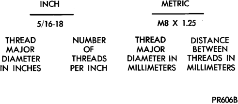
GRADE/CLASS IDENTIFICATION
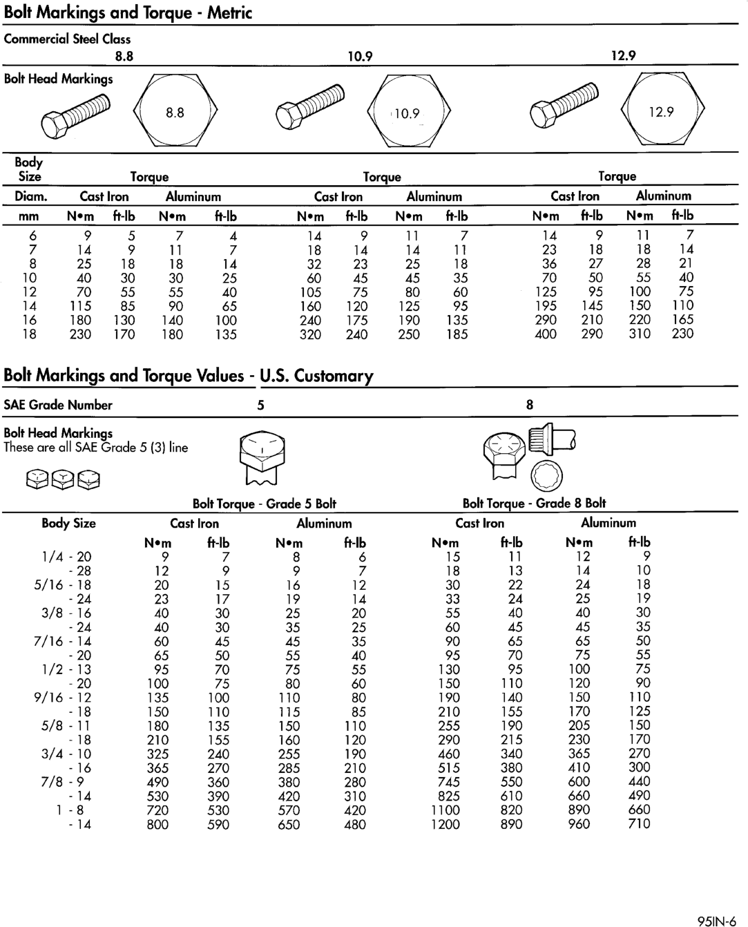
The SAE bolt strength grades range from grade 2 to grade 8. The higher the grade number, the greater the bolt strength. Identification is determined by the line marks on the top of each bolt head. The actual bolt strength grade corresponds to the number of line marks plus 2. The most commonly used metric bolt strength classes are 9.8 and 12.9. The metric strength class identification number is imprinted on the head of the bolt. The higher the class number, the greater the bolt strength. Some metric nuts are imprinted with a single-digit strength class on the nut face. Refer to the Fastener Identification and Fastener Strength Charts.


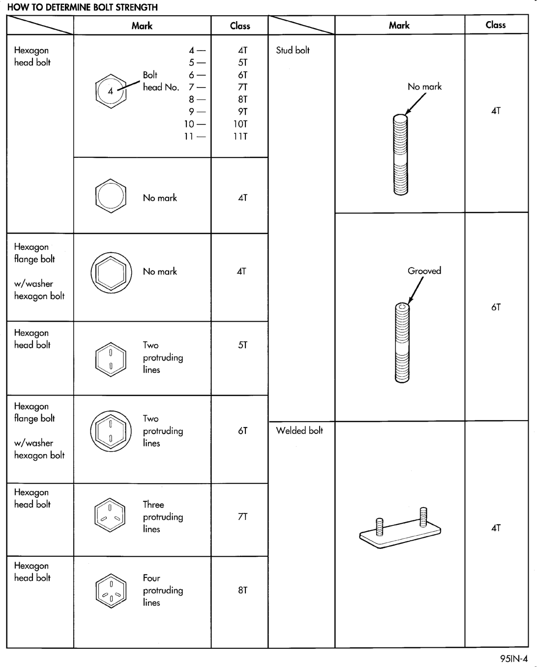
= SO
Hexagon 4— AT Stud bolt
head bolt 5— 5T
Bolt 6— 61
4 head No. 7 — 7T No mark
g— 8T
9— 9T AT
10 — 10T
11— 11T
Hexagon
flange bolt
No mark AT Grooved
w/washer
hexagon bolt
éT
Hexagon
head bolt Two 5T
protruding
lines
Hexagon
flange bolt Two
protruding éT Welded bolt
w/washer lines
hexagon bolt
Hexagon
head bolt Three
protruding 7T
lines AT
Hexagon
head bolt 0 Four
protruding 8T
0 lines
95IN-4
FASTENER USAGE
WARNING: USE OF AN INCORRECT FASTENER MAY RESULT IN COMPONENT DAMAGE OR PER- SONAL INJURY.
Figure art, specifications and torque references in this Service Manual are identified in metric and SAE format.
During any maintenance or repair procedures, it is important to salvage all fasteners (nuts, bolts, etc.) for reassembly. If the fastener is not salvageable, a fastener of equivalent specification must be used.
THREADED HOLE REPAIR
Most stripped threaded holes can be repaired using a Helicoilt. Follow the manufactures recommendations for application and repair procedures.
METRIC SYSTEM
WARNING: USE OF AN INCORRECT FASTENER MAY RESULT IN COMPONENT DAMAGE OR PER- SONAL INJURY.
Figure art, specifications and torque references in this Service Manual are identified in metric and SAE format.
CONVERSION FORMULAS AND EQUIVALENT VALUES
During any maintenance or repair procedures, it is important to salvage metric fasteners (nuts, bolts, etc.) for reassembly. If the fastener is not salvageable, a fastener of equivalent specification should be used.
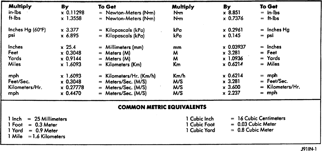
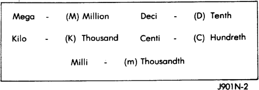
The metric system is based on quantities of one, ten, one hundred, one thousand and one million (Fig. 4).
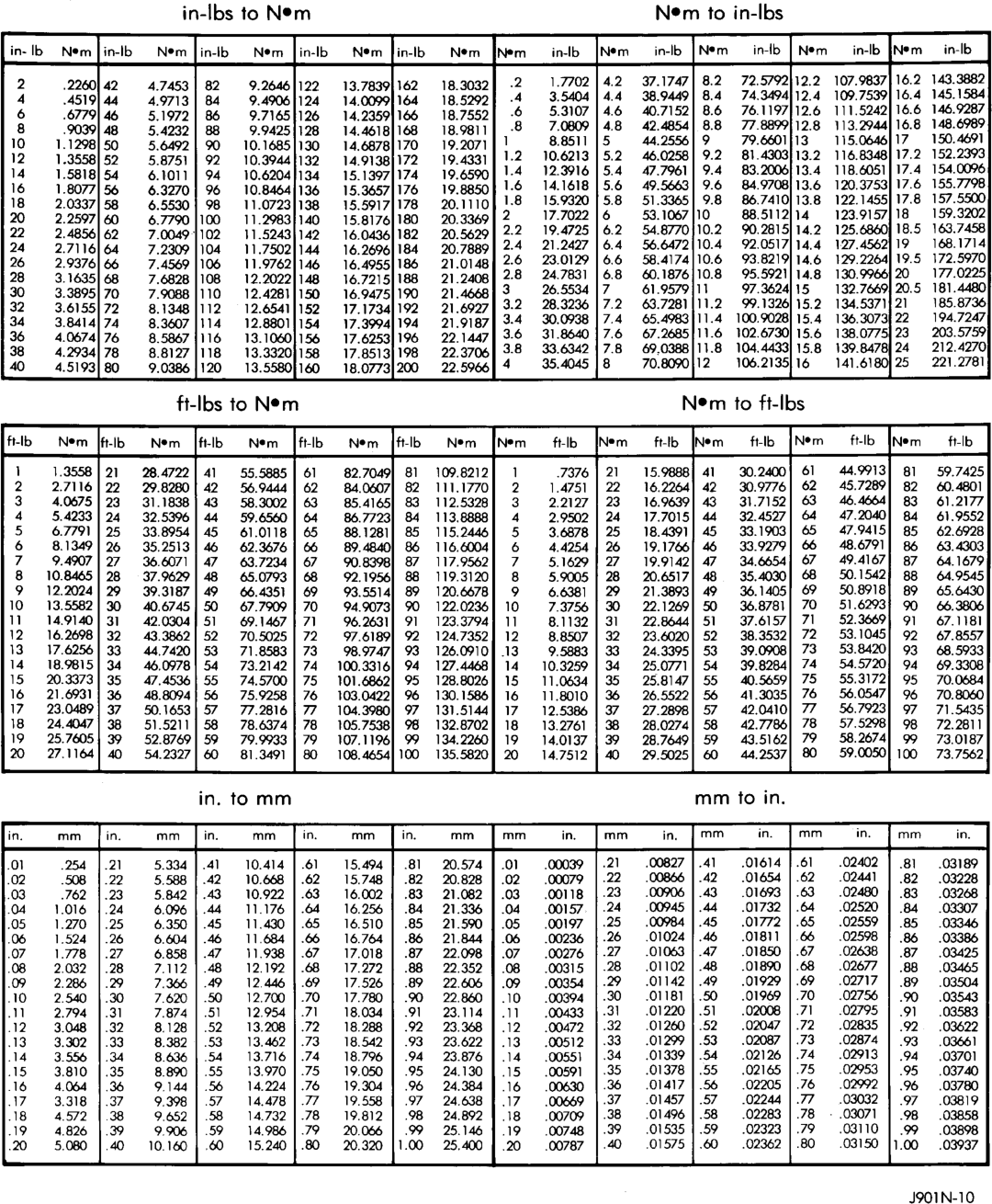
The following chart will assist in converting metric units to equivalent English and SAE units, or vise versa.
Refer to the Metric Conversion chart to convert torque values listed in metric Newton- meters (N·m). Also, use the chart to convert between millimeters (mm) and inches (in.)

TORQUE REFERENCES
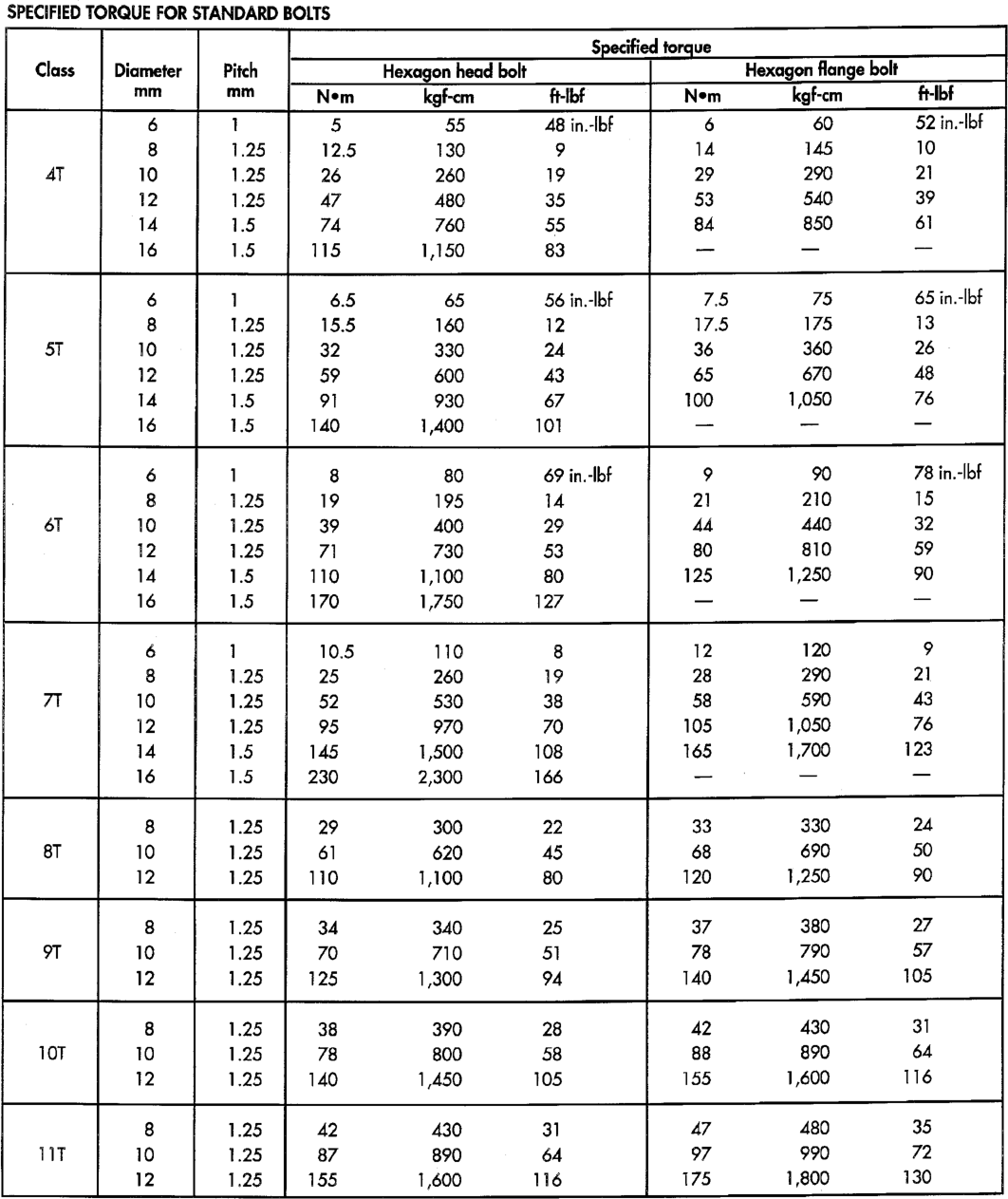
Individual Torque Charts appear at the end of many Groups. Refer to the Standard Torque Specifi-
TORQUE SPECIFICATIONS
| coe Specified torque
Class Diameter Hexagon head bolt Hexagon flange bolt
mm ey Nem kgfom
6 1 5 55 AB in.-lbf 6 60 52 in.-lbf
8 1.25 12.5 130 9 14 145 10
| 47 10 1.25 26 260 19 | 29 290 21
12 1.25 | 47 480 35 53 540 39
14 1.5 74 760 55 84 850 61
16 1.5 115 1,150 83 — — —
6 | 1 6.5 65 56 in.-lbf 7.5 75 65 in.-lbf
8 1.25 15.5 160 12 17.5 175 13
| st | 10 1.25 | 32 330 24 36 360 26 |
| 12 1.25 59 600 43 65 670 48
14 1.5 91 930 67 100 1,050 76
16 1.5 140 1,400 101 — _ —
| re | 8 80 69 in.-lbf 9 90 78 in.-lbf
|. 8 | 1.25 | 19 195 14 21 210 15
| oT | 10 | 1.25 | 39 400 29 4A 440 32
| | 120 | 1.25 | 730 53 |} 80 810 59 |
14 1.5 110 1,100 80 125 1,250 90
| | 16 1.5 170 1,750 127 — _ —
| 6 | 1 | 10.5 110 8 12 120 9 |
| 8 | 1.25 | 25 260 19 28 290 21
| 7m | 10 | 1.25 | 52 530 38 58 590 43
| 12 | 125 | 95 970 70 105 1,050 76
| | 14 1.5 | 145 1,500 108 165 1,700 123
| 16 1.5 230 2,300 166 — _— —
8 1.25 29 300 22 33 330 24
8T 10 1.25 61 620 A5 | 68 690 50
12 1.25 110 1,100 80 120 1,250 90
8 1.25 34 340 25 37 380 27
9T 10 1.25 70 710 5] 78 790 57
12 1.25 125 1,300 94 140 1,450 105
8 1.25 38 390 28 42 430 31
10T 10 1.25 78 800 58 88 890 64
12 1.25 140 1,450 105 155 1,600 116
| | 8 1.25 42 430 31 47 480 35 |
11T 10 1.25 87 890 64 97 990 72 |
12 1.25 155 1,600 116 | 175 1,800 130
cations Chart for torque references not listed in the individual torque charts.
E-MARK LABEL
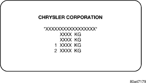
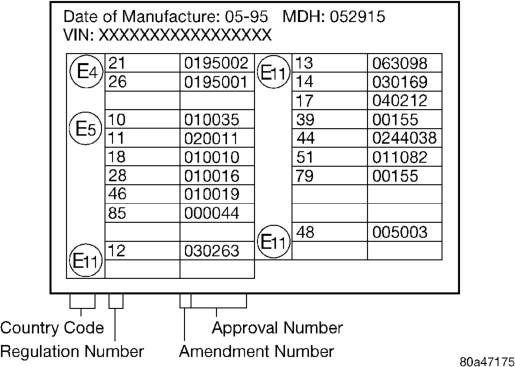
An E-mark Label (Fig. 1) is located on the rear shut face of the driver's door. The label contains the following information:
• Date of Manufacture • Month-Day-Hour (MDH) • Vehicle Identification Number (VIN) • Country Codes • Regulation Number • Regulation Amendment Number • Approval Number
MANUFACTURER PLATE
The Manufacturer Plate (Fig. 2) is located in the engine compartment on the radiator closure panel crossmember adjacent to the Body Code Plate. The plate contains five lines of information:
1. Vehicle Identification Number (VIN) 2. Gross Vehicle Mass (GVM) 3. Gross Train Mass (GTM) 4. Gross Front Axle Rating (GFAR) 5. Gross Rear Axle Rating (GRAR)