Instrument Panel Systems — part 2 of 2 — 1998 Jeep Grand Cherokee ZJ Export Service Manual
← Contents 1 2
Pages 432–442 · 11 pages · 1 words repaired
(4) Pull the cluster bezel rearward and move it to the outboard side of the steering wheel to remove it from the instrument panel.
(5) Reverse the removal procedures to install. Tighten the mounting screws to 2.2 N·m (20 in. lbs.).
INSTRUMENT CLUSTER
WARNING: ON VEHICLES EQUIPPED WITH AIR- BAGS, REFER TO GROUP 8M - PASSIVE RESTRAINT SYSTEMS BEFORE ATTEMPTING ANY STEERING WHEEL, STEERING COLUMN, OR INSTRUMENT PANEL COMPONENT DIAGNOSIS OR SERVICE. FAILURE TO TAKE THE PROPER PRE- CAUTIONS COULD RESULT IN ACCIDENTAL AIR- BAG DEPLOYMENT AND POSSIBLE PERSONAL INJURY.
(1) Remove the cluster bezel from the instrument panel. See Cluster Bezel in this group for the procedures.
(2) Remove the two screws that secure each end of the instrument cluster to the instrument panel.
(3) Pull the instrument cluster rearward to disengage the self-docking wire harness connector.
NOTE: The instrument cluster has a self-docking wire harness connector that will be automatically aligned with, and connected to the instrument panel
wire harness when the cluster is installed in the instrument panel.
(4) Remove the instrument cluster from the instrument panel.
(5) Reverse the removal procedures to install. Tighten the mounting screws to 2.2 N·m (20 in. lbs.).
CLUSTER LENS, HOOD, AND MASK
WARNING: ON VEHICLES EQUIPPED WITH AIR- BAGS, REFER TO GROUP 8M - PASSIVE RESTRAINT SYSTEMS BEFORE ATTEMPTING STEERING WHEEL, STEERING COLUMN, OR INSTRUMENT PANEL COMPONENT DIAGNOSIS OR SERVICE. FAILURE TO TAKE THE PROPER PRE- CAUTIONS COULD RESULT IN ACCIDENTAL AIR- BAG DEPLOYMENT AND POSSIBLE PERSONAL INJURY.
(1) Remove the cluster bezel as described in this group.
(2) Remove the instrument cluster as described in this group.
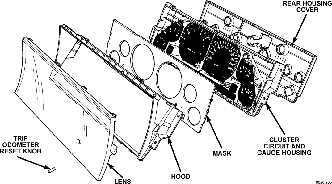
(3) Remove the trip odometer reset knob by pulling it off of the switch stem (Fig. 6). (4) Depress the snap clips that secure the cluster lens to the cluster hood and gently pull the lens away from the hood.
(5) Depress the snap clips that secure the cluster hood to the cluster circuit and gauge housing and gently pull the hood away from the housing.
(6) Gently lift the gauge mask away from the locating pins on the front of the cluster circuit and gauge housing.
(7) Reverse the removal procedures to install.
GAUGE
WARNING: ON VEHICLES EQUIPPED WITH AIR- BAGS, REFER TO GROUP 8M - PASSIVE RESTRAINT SYSTEMS BEFORE ATTEMPTING STEERING WHEEL, STEERING COLUMN, OR INSTRUMENT PANEL COMPONENT DIAGNOSIS OR
SERVICE. FAILURE TO TAKE THE PROPER PRE- CAUTIONS COULD RESULT IN ACCIDENTAL AIR- BAG DEPLOYMENT AND POSSIBLE PERSONAL INJURY.
(1) Remove the cluster lens, hood, and mask as described in this group.
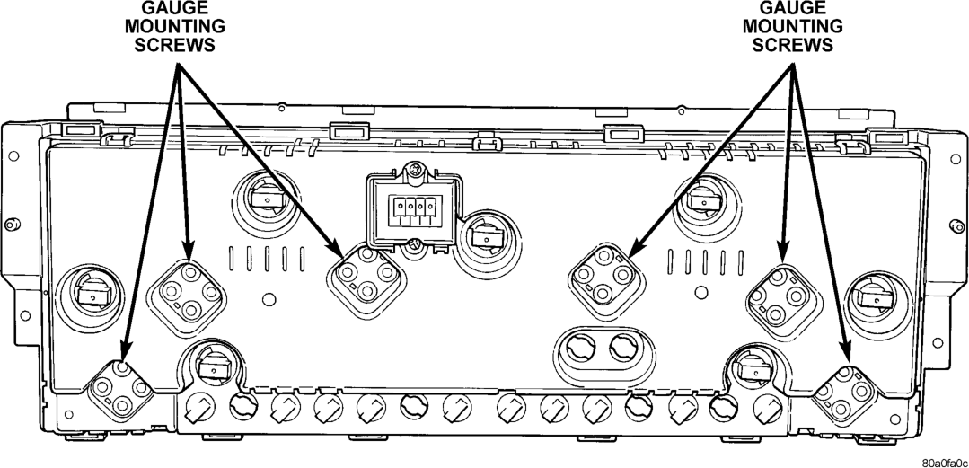
(2) Remove the screws that secure the gauge(s) from the rear of the cluster circuit and gauge housing (Fig. 7).
(3) Remove the gauge(s) from the front of the cluster circuit and gauge housing.
(4) Reverse the removal procedures to install.
CLUSTER BULB
WARNING: ON VEHICLES EQUIPPED WITH AIR- BAGS, REFER TO GROUP 8M - PASSIVE RESTRAINT SYSTEMS BEFORE ATTEMPTING ANY STEERING WHEEL, STEERING COLUMN, OR INSTRUMENT PANEL COMPONENT DIAGNOSIS OR SERVICE. FAILURE TO TAKE THE PROPER PRE- CAUTIONS COULD RESULT IN ACCIDENTAL AIR- BAG DEPLOYMENT AND POSSIBLE PERSONAL INJURY.
(1) Remove the instrument cluster from the instrument panel. See Instrument Cluster in this group for the procedures.
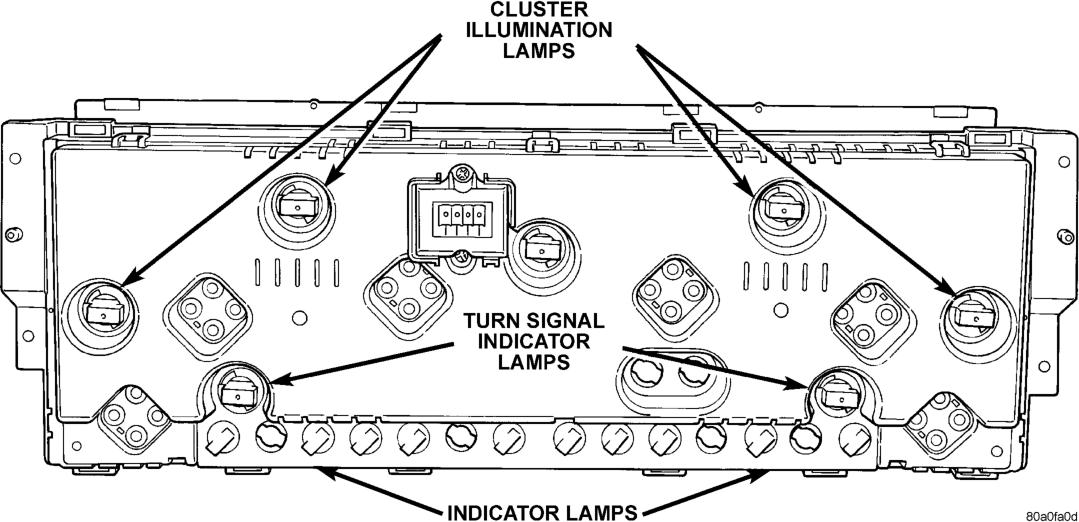
(2) Remove the bulb and bulb holder from the circuit board on the rear of the cluster housing by turning the holder counterclockwise (Fig. 8).
CAUTION: Always use the correct bulb size and type for replacement. An incorrect bulb size or type may overheat and cause damage to the instrument cluster circuit board and/or the gauges.
(3) Reverse the removal procedures to install.
OUTBOARD SWITCH POD
WARNING: ON VEHICLES EQUIPPED WITH AIR- BAGS, REFER TO GROUP 8M - PASSIVE RESTRAINT SYSTEMS BEFORE ATTEMPTING ANY STEERING WHEEL, STEERING COLUMN, OR INSTRUMENT PANEL COMPONENT DIAGNOSIS OR
SERVICE. FAILURE TO TAKE THE PROPER PRE- CAUTIONS COULD RESULT IN ACCIDENTAL AIR- BAG DEPLOYMENT AND POSSIBLE PERSONAL INJURY.
(1) Remove the cluster bezel from the instrument panel. See Cluster Bezel in this group for the procedures.
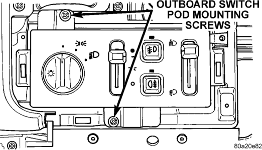
(2) Remove the two screws that secure the outboard switch pod to the instrument panel (Fig. 9).
(3) Pull the outboard switch pod out from the instrument panel far enough to unplug the wire harness connectors.
(4) Remove the outboard switch pod from the instrument panel. (5) Reverse the removal procedures to install. Tighten the mounting screws to 2.2 N·m (20 in. lbs.).
INBOARD SWITCH POD
WARNING: ON VEHICLES EQUIPPED WITH AIR- BAGS, REFER TO GROUP 8M - PASSIVE RESTRAINT SYSTEMS BEFORE ATTEMPTING ANY STEERING WHEEL, STEERING COLUMN, OR INSTRUMENT PANEL COMPONENT DIAGNOSIS OR SERVICE. FAILURE TO TAKE THE PROPER PRE- CAUTIONS COULD RESULT IN ACCIDENTAL AIR- BAG DEPLOYMENT AND POSSIBLE PERSONAL INJURY.
(1) Remove the cluster bezel from the instrument panel. See Cluster Bezel in this group for the procedures.
(2) Remove the two screws that secure the inboard switch pod to the instrument panel (Fig. 10).
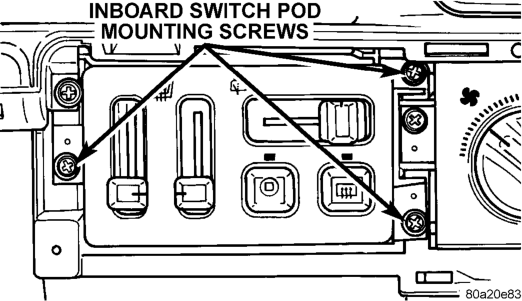
(3) Pull the inboard switch pod out from the instrument panel far enough to unplug the wire harness connectors.
(4) Remove the inboard switch pod from the instrument panel. (5) Reverse the removal procedures to install. Tighten the mounting screws to 2.2 N·m (20 in. lbs.).
BODY CONTROL MODULE
Before replacing the Body Control Module (BCM), use a DRB scan tool to determine the current settings for the BCM programmable features. These settings should be duplicated in the replacement BCM using the DRB scan tool, before returning the vehicle to service.
WARNING: ON VEHICLES EQUIPPED WITH AIR- BAGS, REFER TO GROUP 8M - PASSIVE RESTRAINT SYSTEMS BEFORE ATTEMPTING ANY STEERING WHEEL, STEERING COLUMN, OR INSTRUMENT PANEL COMPONENT DIAGNOSIS OR SERVICE. FAILURE TO TAKE THE PROPER PRE- CAUTIONS COULD RESULT IN ACCIDENTAL AIR- BAG DEPLOYMENT AND POSSIBLE PERSONAL INJURY.
(1) Remove the steering column opening cover/ knee blocker from the instrument panel. See Steering Column Opening Cover and Knee Blocker in this group for the procedures.
(2) Remove the four screws located below the outboard switch pod that secure the Body Control Module (BCM) to the instrument panel armature (Fig. 11).
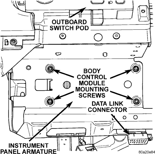
(3) Move the BCM towards the steering column far enough to access the three wire harness connectors.
(4) Unplug the wire harness connectors from the BCM.
(5) Remove the BCM from the instrument panel. (6) Reverse the removal procedures to install. Tighten the mounting screws to 2.2 N·m (20 in. lbs.).
NOTE: If a new Body Control Module is installed, the programmable features must be enabled and/or disabled to the customer's preferred settings. Use a DRB scan tool and the proper Diagnostic Procedures manual to perform these operations.
GLOVE BOX MODULE
WARNING: ON VEHICLES EQUIPPED WITH AIR- BAGS, REFER TO GROUP 8M - PASSIVE RESTRAINT SYSTEMS BEFORE ATTEMPTING ANY STEERING WHEEL, STEERING COLUMN, OR INSTRUMENT PANEL COMPONENT DIAGNOSIS OR SERVICE. FAILURE TO TAKE THE PROPER PRE- CAUTIONS COULD RESULT IN ACCIDENTAL AIR- BAG DEPLOYMENT AND POSSIBLE PERSONAL INJURY.
(1) Remove the steering column opening cover/ knee blocker from the instrument panel. See Steering Column Opening Cover and Knee Blocker in this group for the procedures.
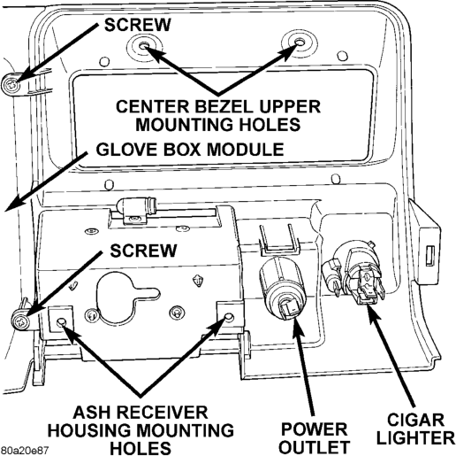
(2) Remove the two screws that secure the top of the instrument panel center bezel to the instrument panel above the Graphic Display Module (GDM) or Vehicle Information Center (VIC).
(3) Remove the ash receiver from the instrument panel center bezel.
(4) Remove the two screws in the back of the ash receiver opening that secure the instrument panel center bezel to the instrument panel armature.
(5) Remove the screw that secures the courtesy lamp to the lower instrument panel located under the outboard end of the glove box module.
(6) Open the passenger side front door and remove the screw that secures the outboard end of the glove box module to the instrument panel armature.
(7) Remove the four screws that secure the glove box hinge to the instrument panel armature on the lower edge of the glove box module.
(8) Open the glove box door and remove the four screws at the top of the glove box opening that secure the upper edge of the glove box module to the instrument panel armature.
(9) Lower the glove box module far enough to access and unplug the wire harness connectors from the glove box lamp and switch, the cigar lighter and lamp, and the power outlet. Also remove the ash receiver lamp bulb and socket as a unit by gently pulling it out of the ash receiver lamp hood.
(10) Remove the glove box module from the instrument panel.
(11) Reverse the removal procedures to install. Tighten the mounting screws to 2.2 N·m (20 in. lbs.).
GRAPHIC DISPLAY MODULE AND VEHICLE INFORMATION CENTER
WARNING: ON VEHICLES EQUIPPED WITH AIR- BAGS, REFER TO GROUP 8M - PASSIVE RESTRAINT SYSTEMS BEFORE ATTEMPTING ANY STEERING WHEEL, STEERING COLUMN, OR INSTRUMENT PANEL COMPONENT DIAGNOSIS OR
SERVICE. FAILURE TO TAKE THE PROPER PRE- CAUTIONS COULD RESULT IN ACCIDENTAL AIR- BAG DEPLOYMENT AND POSSIBLE PERSONAL INJURY.
(1) Remove the glove box module from the instrument panel. See Glove Box Module in this group for the procedures.
(2) Remove the three screws that secure the Graphic Display Module (GDM) or Vehicle Information Center (VIC) to the instrument panel armature (Fig. 12).
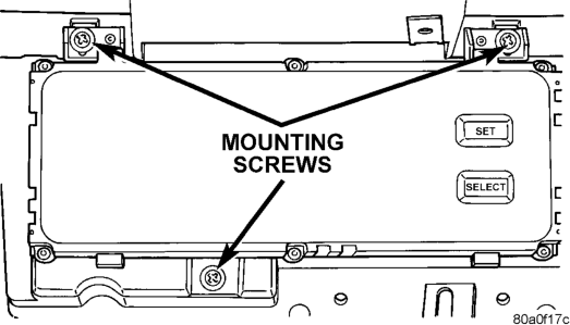
Information Center Remove/Install
(3) Pull the GDM or VIC unit out from the instrument panel far enough to access and unplug the wire harness connector.
(4) Remove the GDM or VIC from the instrument panel.
(5) Reverse the removal procedures to install. Tighten the mounting screws to 2.2 N·m (20 in. lbs.).
GLOVE BOX LAMP AND SWITCH
WARNING: ON VEHICLES EQUIPPED WITH AIR- BAGS, REFER TO GROUP 8M - PASSIVE RESTRAINT SYSTEMS BEFORE ATTEMPTING ANY STEERING WHEEL, STEERING COLUMN, OR INSTRUMENT PANEL COMPONENT DIAGNOSIS OR SERVICE. FAILURE TO TAKE THE PROPER PRE- CAUTIONS COULD RESULT IN ACCIDENTAL AIR- BAG DEPLOYMENT AND POSSIBLE PERSONAL INJURY.
(1) Remove the glove box module from the instrument panel. See Glove Box Module in this group for the procedures.
(2) From the back side of the glove box module, squeeze the retaining tabs on the glove box lamp and switch housing together and push the unit out through the mounting hole towards the front of the module (Fig. 13).
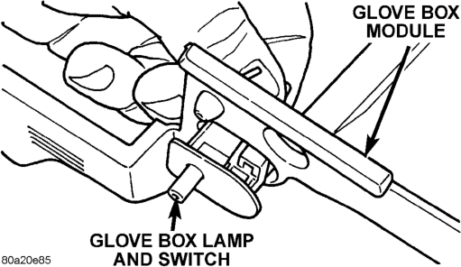
(3) To install the glove box lamp and switch unit, insert the unit through the mounting hole from the front of the glove box module and push in on the unit firmly, until the retaining tabs snap into place.
(4) Reverse the remaining removal procedures to complete the installation.
GLOVE BOX LATCH STRIKER
WARNING: ON VEHICLES EQUIPPED WITH AIR- BAGS, REFER TO GROUP 8M - PASSIVE RESTRAINT SYSTEMS BEFORE ATTEMPTING ANY STEERING WHEEL, STEERING COLUMN, OR INSTRUMENT PANEL COMPONENT DIAGNOSIS OR SERVICE. FAILURE TO TAKE THE PROPER PRE- CAUTIONS COULD RESULT IN ACCIDENTAL AIR- BAG DEPLOYMENT AND POSSIBLE PERSONAL INJURY.
(1) Remove the glove box module from the instrument panel. See Glove Box Module in this group for the procedures.
(2) From the top of the glove box module, straighten the two mounting tabs that secure the glove box latch striker to the glove box module (Fig. 14).
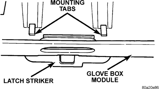
(3) Remove the latch striker through the upper glove box opening of the glove box module.
(4) To install the latch striker, insert the mounting tabs through the slots in the upper glove box opening of the glove box module, and bend the tabs over from the top of the glove box module.
CIGAR LIGHTER
WARNING: ON VEHICLES EQUIPPED WITH AIR- BAGS, REFER TO GROUP 8M - PASSIVE RESTRAINT SYSTEMS BEFORE ATTEMPTING ANY STEERING WHEEL, STEERING COLUMN, OR INSTRUMENT PANEL COMPONENT DIAGNOSIS OR SERVICE. FAILURE TO TAKE THE PROPER PRE- CAUTIONS COULD RESULT IN ACCIDENTAL AIR- BAG DEPLOYMENT AND POSSIBLE PERSONAL INJURY.
(1) Disconnect and isolate the battery negative cable.
(2) Pull the cigar lighter knob and element out of the cigar lighter base.
(3) Look inside the cigar lighter base and note the position of the retaining bosses that secure the unit to the light ring/retainer in the instrument panel center bezel (Fig. 15).
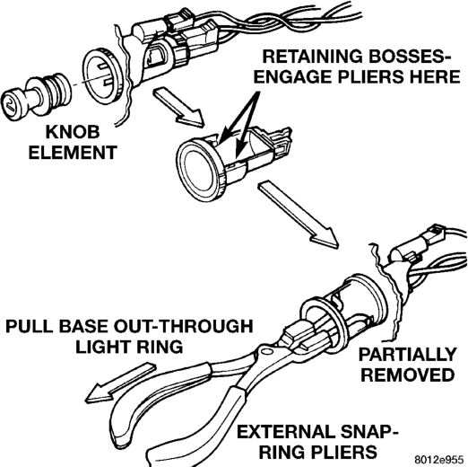
(4) Insert a pair of external snap ring pliers into the cigar lighter base and engage the tips of the pliers with the retaining bosses.
(5) Squeeze the pliers to disengage the retaining bosses from the base, and using a gentle rocking motion pull the pliers and the cigar lighter base out of the light ring/retainer.
(6) Remove the pliers from the cigar lighter base and unplug the cigar lighter wire harness connector.
(7) Remove the cigar lighter light ring/retainer from the instrument panel center bezel and unplug the light ring lamp wire harness connector.
(8) Reverse the removal procedures to install.
POWER OUTLET
WARNING: ON VEHICLES EQUIPPED WITH AIR- BAGS, REFER TO GROUP 8M - PASSIVE RESTRAINT SYSTEMS BEFORE ATTEMPTING ANY STEERING WHEEL, STEERING COLUMN, OR INSTRUMENT PANEL COMPONENT DIAGNOSIS OR SERVICE. FAILURE TO TAKE THE PROPER PRE- CAUTIONS COULD RESULT IN ACCIDENTAL AIR- BAG DEPLOYMENT AND POSSIBLE PERSONAL INJURY.
(1) Remove the glove box module from the instrument panel. See Glove Box Module in this group for the procedures.
(2) From the rear of the instrument panel center bezel, unscrew the power outlet receptacle shell clamp from the power outlet receptacle shell base.
(3) Remove the power outlet receptacle shell base from the front of the instrument panel center bezel.
(4) Reverse the removal procedures to install.
POWER OUTLET DOOR
(1) Insert a trim stick or another suitable wide flat-bladed tool between the side of the power outlet housing in the instrument panel center bezel and the upper pivot area of the power outlet door.
(2) Pry gently against the upper pivot area of the power outlet door until the door pivot pin clears the pivot receptacle in the instrument panel center bezel.
(3) Pull the power outlet door out of the power outlet housing using a twisting motion.
(4) To install the door, insert one of the pivot pins into a pivot receptacle in the instrument panel center bezel and twist the door gently until the pivot pin on the opposite side of the door snaps into the other center bezel pivot receptacle.
INSTRUMENT PANEL CENTER BEZEL
WARNING: ON VEHICLES EQUIPPED WITH AIR- BAGS, REFER TO GROUP 8M - PASSIVE RESTRAINT SYSTEMS BEFORE ATTEMPTING ANY STEERING WHEEL, STEERING COLUMN, OR INSTRUMENT PANEL COMPONENT DIAGNOSIS OR SERVICE. FAILURE TO TAKE THE PROPER PRE- CAUTIONS COULD RESULT IN ACCIDENTAL AIR-
BAG DEPLOYMENT AND POSSIBLE PERSONAL INJURY.
(1) Remove the glove box module from the instrument panel. See Glove Box Module in this group for the procedures.
(2) Remove the two screws located on the back side of the glove box module that secure the instrument panel center bezel to the inboard end of the glove box module (Fig. 16).
Install
(3) Reverse the removal procedures to install. Tighten the mounting screws to 2.2 N·m (20 in. lbs.).
GLOVE BOX
WARNING: ON VEHICLES EQUIPPED WITH AIR- BAGS, REFER TO GROUP 8M - PASSIVE RESTRAINT SYSTEMS BEFORE ATTEMPTING ANY STEERING WHEEL, STEERING COLUMN, OR INSTRUMENT PANEL COMPONENT DIAGNOSIS OR SERVICE. FAILURE TO TAKE THE PROPER PRE- CAUTIONS COULD RESULT IN ACCIDENTAL AIR- BAG DEPLOYMENT AND POSSIBLE PERSONAL INJURY.
(1) Disconnect and isolate the battery negative cable.
(2) Drill out the two rivets that secure the glove box hinge to the lower edge of the glove box module (Fig. 17).
NOTE: The rivets are used to ease assembly during the manufacturing process, but do not require replacement following service.
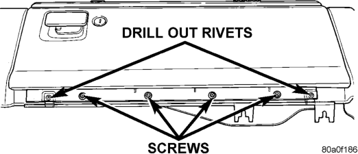
(3) Remove the four screws that secure the glove box hinge to the instrument panel armature.
(4) Release the glove box latch and remove the glove box from the glove box module.
(5) Reverse the removal procedures to install. Tighten the mounting screws to 2.2 N·m (20 in. lbs.).
GLOVE BOX COMPONENTS
The glove box bezel is the only component of the glove box that can be serviced without glove box removal. All other components will require that the glove box be removed from the instrument panel.
GLOVE BOX BEZEL
(1) Open the glove box. (2) Remove the two screws that secure the bezel to the glove box near the top of the glove box inner door panel (Fig. 18).
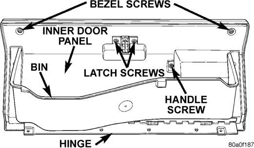
(3) Using a trim stick or another suitable wide flat-bladed tool, gently pry the bezel away from the outside of the glove box door. There is double-faced adhesive tape between the bezel and the outer door panel.
(4) Reverse the removal procedures to install. Tighten the mounting screws to 2.2 N·m (20 in. lbs.).
GLOVE BOX HINGE
(1) Remove the glove box from the instrument panel. See Glove Box in this group for the procedures.
(2) Remove the screws that secure the glove box hinge to the glove box inner door panel.
(3) Remove the glove box hinge from the glove box door.
(4) Reverse the removal procedures to install. Tighten the mounting screws to 2.2 N·m (20 in. lbs.).
GLOVE BOX BIN
(1) Remove the glove box hinge from the glove box door. See Glove Box Hinge in this group for the procedures.
(2) Remove the screws that secure each side of the glove box bin to the glove box door.
(3) Remove the glove box bin from the glove box door.
(4) Reverse the removal procedures to install. Tighten the mounting screws to 2.2 N·m (20 in. lbs.).
GLOVE BOX LATCH AND HANDLE
(1) Remove the glove box bin from the glove box door. See Glove Box Bin in this group for the procedures.
(2) Remove the two bezel screws, two latch screws, and one handle screw from the glove box inner door panel.
(3) Remove the glove box inner door panel from the glove box outer door panel.
(4) Remove the screw that secures the glove box latch and handle to the inside of the glove box outer door panel (Fig. 19).
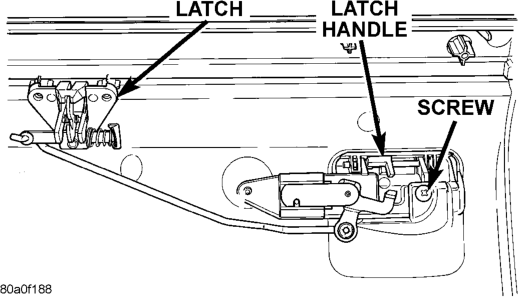
(5) Remove the latch and handle from the glove box door as a unit.
(6) Reverse the removal procedures to install. Tighten the mounting screws to 2.2 N·m (20 in. lbs.).
GLOVE BOX LOCK CYLINDER
(1) Remove the glove box latch and handle from the glove box. See Glove Box Latch and Handle in this group for the procedures.
(2) Insert the glove box key into the glove box lock cylinder.
(3) Insert a small screwdriver into the retaining tumbler release slot and depress the retaining tumbler (Fig. 20).
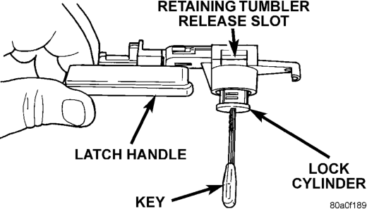
(4) Pull the lock cylinder out of the latch handle by using a gentle twisting and pulling action on the key.
(5) Reverse the removal procedures to install.
COWL TOP TRIM PANEL
WARNING: ON VEHICLES EQUIPPED WITH AIR- BAGS, REFER TO GROUP 8M - PASSIVE RESTRAINT SYSTEMS BEFORE ATTEMPTING ANY STEERING WHEEL, STEERING COLUMN, OR INSTRUMENT PANEL COMPONENT DIAGNOSIS OR SERVICE. FAILURE TO TAKE THE PROPER PRE- CAUTIONS COULD RESULT IN ACCIDENTAL AIR- BAG DEPLOYMENT AND POSSIBLE PERSONAL INJURY.
(1) Disconnect and isolate the battery negative cable.
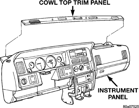
(2) Using a trim stick or another suitable wide flat-bladed tool, gently pry the cowl top trim panel off of the instrument panel top pad (Fig. 21).
(3) Pull the trim panel up far enough to access and unplug the wire harness connector for the solar sensor, or to remove the solar sensor from the cowl top trim, if the vehicle is so equipped.
(4) Remove the cowl top trim panel from the instrument panel. (5) Reverse the removal procedures to install.
INSTRUMENT PANEL TOP PAD
WARNING: ON VEHICLES EQUIPPED WITH AIR- BAGS, REFER TO GROUP 8M - PASSIVE
RESTRAINT SYSTEMS BEFORE ATTEMPTING ANY STEERING WHEEL, STEERING COLUMN, OR INSTRUMENT PANEL COMPONENT DIAGNOSIS OR SERVICE. FAILURE TO TAKE THE PROPER PRE- CAUTIONS COULD RESULT IN ACCIDENTAL AIR- BAG DEPLOYMENT AND POSSIBLE PERSONAL INJURY.
NOTE: Be sure when replacing the instrument panel top pad that all airbag warning labels are in place.
(1) Disconnect and isolate the battery negative cable.
(2) Remove the steering column opening cover and knee blocker from the instrument panel. See Steering Column Opening Cover and Knee Blocker in this group for the procedures.
(3) Remove the cluster bezel from the instrument panel. See Cluster Bezel in this group for the procedures.
(4) Remove the glove box module from the instrument panel. See Glove Box Module in this group for the procedures.
(5) Remove the cowl top trim panel from the instrument panel. See Cowl Top Trim Panel in this group for the procedures.
(6) If the vehicle is so equipped, remove the screw that secures the auto headlamp light sensor/vehicle theft security system lamp to the top of the instrument panel near the defroster duct outlet, and move it far enough for clearance during removal of the instrument panel top pad. (7) Remove all of the screws that secure the perimeter of the instrument panel top pad to the instrument panel armature.
(8) Remove the instrument panel top pad from the instrument panel armature.
(9) Reverse the removal procedures to install. Tighten the mounting screws to 2.2 N·m (20 in. lbs.).
JUNCTION BLOCK
WARNING: ON VEHICLES EQUIPPED WITH AIR- BAGS, REFER TO GROUP 8M - PASSIVE RESTRAINT SYSTEMS BEFORE ATTEMPTING ANY STEERING WHEEL, STEERING COLUMN, OR INSTRUMENT PANEL COMPONENT DIAGNOSIS OR SERVICE. FAILURE TO TAKE THE PROPER PRE- CAUTIONS COULD RESULT IN ACCIDENTAL AIR- BAG DEPLOYMENT AND POSSIBLE PERSONAL INJURY.
(1) Disconnect and isolate the battery negative cable.
(2) Remove the fuse access panel by unsnapping it from the right cowl side trim panel.
(3) Remove the push nut that secures the right cowl side trim panel to the junction block stud (Fig. 22).
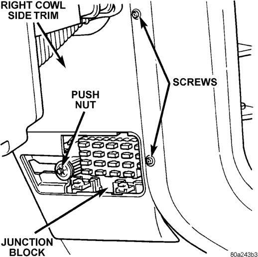
(4) Remove the two screws that secure the right cowl side trim panel to the right front door opening trim.
(5) Remove the right cowl side trim panel from the right cowl side inner panel.
(6) Unplug all of the wire harness connectors from the junction block cavities.
(7) Remove the two screws that secure the junction block to the mounting bracket on the right cowl side inner panel.
(8) Remove the junction block from the mounting bracket on the right cowl side inner panel.
(9) Reverse the removal procedures to install. Tighten the mounting screws to 2.2 N·m (20 in. lbs.).
INSTRUMENT PANEL ASSEMBLY
WARNING: ON VEHICLES EQUIPPED WITH AIR- BAGS, REFER TO GROUP 8M - PASSIVE RESTRAINT SYSTEMS BEFORE ATTEMPTING ANY STEERING WHEEL, STEERING COLUMN, OR INSTRUMENT PANEL COMPONENT DIAGNOSIS OR SERVICE. FAILURE TO TAKE THE PROPER PRE- CAUTIONS COULD RESULT IN ACCIDENTAL AIR- BAG DEPLOYMENT AND POSSIBLE PERSONAL INJURY.
(1) Disconnect and isolate the battery negative cable.
(2) Remove the steering column opening cover and knee blocker from the instrument panel. See Steering Column Opening Cover and Knee Blocker in this group for the procedures.
(3) Remove the bolts that secure the lower instrument panel reinforcement to the instrument panel armature and remove the reinforcement (Fig. 23).
(4) Remove the upper and lower steering column shrouds from the steering column. Refer to Group 19 - Steering for the procedures.
(5) Unplug all of the wire harness connectors from the steering column-mounted components and switches.
(6) Remove the three nuts that secure the steering column toe plate to the dash panel at the base of the steering column.
(7) Remove the two nuts that secure the steering column mounting bracket to the studs on the steering column and brake pedal support. Lower the steering column to the floor.
(8) Remove both cowl side trim panels. Refer to Group 23 - Body for the procedures.
(9) Unplug the instrument panel to body wire harness connector under the left end of the instrument panel.
(10) Unplug the brake lamp switch wire harness connector.
(11) Unplug the instrument panel to heater-A/C housing vacuum harness connector (manual temperature control only) and wire harness connector located under the passenger side end of the instrument panel.
(12) Unplug the radio antenna coaxial cable connector near the right cowl side panel.
(13) Unplug all of the instrument panel wire harness connectors from the junction block on the right cowl side panel.
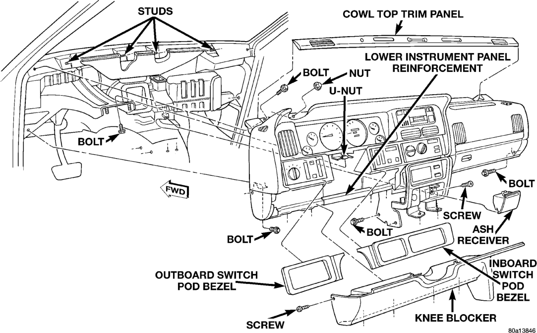
(14) If the vehicle is so equipped, disconnect the in-car temperature sensor aspirator hose at the coupling near the passenger side of the transmission floor tunnel.
(15) On Left-Hand Drive (LHD) models only, remove the ash receiver and remove the screw in the back of the ash receiver housing that secures the instrument panel armature to the heater-A/C housing. (16) Pull back the floor carpet on the transmission floor tunnel from the base of the instrument panel center bezel and remove the two bolts that secure the instrument panel center bracket to the floor. (17) Remove the two bolts that secure the instrument panel center bracket to the driver side of the transmission floor tunnel.
(18) Remove the bolt that secures the instrument panel armature to the steering column and brake pedal support.
(19) Remove the two bolts that secure the ends of the instrument panel armature to the cowl side inner panels.
(20) Remove the cowl top trim panel from the instrument panel. See Cowl Top Trim Panel in this group for the procedures.
(21) Remove the two bolts that secure the ends of the instrument panel armature to the windshield fence.
(22) Remove the four nuts that secure the top of the instrument panel armature to the studs on the windshield fence.
(23) With the aid of an assistant, lift the instrument panel off of the windshield fence studs and maneuver the assembly out of the vehicle through the passenger side front door.
(24) Reverse the removal procedures to install. Tighten the mounting hardware as follows:
• Instrument panel center bracket to floor pan transmission tunnel fasteners - 28 N·m (250 in. lbs.)
• Instrument panel to windshield fence bolts and nuts - 12 N·m (105 in. lbs.)
• Instrument panel to cowl side inner panel bolts - 12 N·m (105 in. lbs.)
• Instrument panel to steering column support bolt - 12 N·m (105 in. lbs.).