Ignition System — 1998 Jeep Grand Cherokee ZJ Export Service Manual
Pages 345–369 · 25 pages · 10 words repaired
GENERAL INFORMATION
INTRODUCTION
This group describes the ignition systems for 5.2L/ 5.9L V–8 and 4.0L 6–cylinder engines.
On Board Diagnostics is described in Group 25, Emission Control Systems.
Group 0, Lubrication and Maintenance, contains general maintenance information (in time or mileage intervals) for ignition related items. The Owner's Manual also contains maintenance information.
DESCRIPTION AND OPERATION
IGNITION SYSTEM
The ignition systems used on 5.2L/5.9L V–8 and 4.0L 6–cylinder engines are basically identical. Similarities and differences between the systems will be discussed.
The ignition system is controlled by the powertrain control module (PCM) on all engines.
The ignition system consists of: • Spark Plugs • Ignition Coil • Secondary Ignition Cables • Distributor (contains rotor and camshaft position sensor)
• Powertrain Control Module (PCM) • Crankshaft Position, Camshaft Position, Throttle Position and MAP Sensors
POWERTRAIN CONTROL MODULE (PCM)
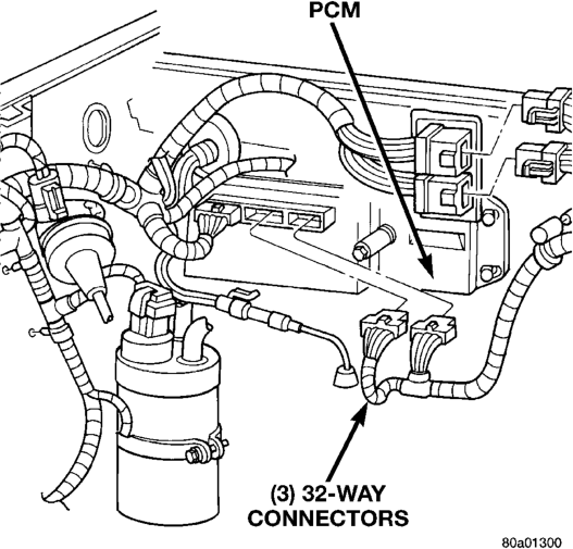
The Powertrain Control Module (PCM) is located in the engine compartment (Fig. 1). The ignition system is controlled by the PCM.
NOTE: Base ignition timing by rotation of distributor is not adjustable.
The PCM opens and closes the ignition coil ground circuit to operate the ignition coil. This is done to adjust ignition timing, both initial (base) and advance, and for changing engine operating conditions.
The amount of electronic spark advance provided by the PCM is determined by five input factors: engine coolant temperature, engine rpm, intake manifold temperature, manifold absolute pressure and throttle position.
DISTRIBUTOR
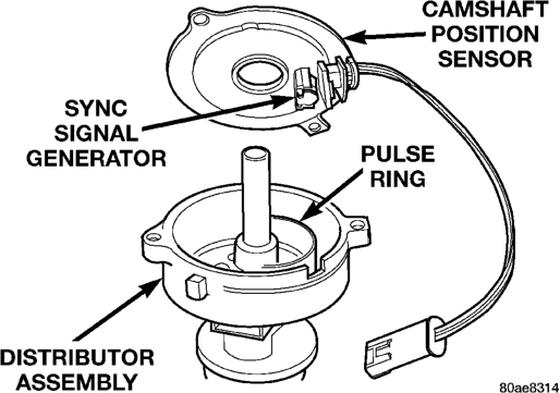
All 4.0L/5.2L/5.9L engines are equipped with a camshaft driven mechanical distributor containing a shaft driven distributor rotor. All distributors are equipped with an internal camshaft position (fuel
sync) sensor (Fig. 2). This sensor provides fuel injection synchronization and cylinder identification.
Typical (5.2L/5.9L Shown)
The distributor does not have built in centrifugal or vacuum assisted advance. Base ignition timing and all timing advance is controlled by the powertrain control module (PCM). Because ignition timing is controlled by the PCM, base ignition timing is not adjustable on any of these engines.
On the 4.0L 6–cylinder engine, the distributor is locked in place by a fork with a slot located on the distributor housing base. The distributor holddown clamp bolt passes through this slot when installed. Because the distributor position is locked when installed, its rotational position can not be changed.
Do not attempt to modify the distributor housing to get distributor rotation. Distributor position will have no effect on ignition timing. The position of the distributor will determine fuel synchronization only.
All 4.0L/5.2L/5.9L distributors contain an internal oil seal that prevents oil from entering the distributor housing. The seal is not serviceable.
SPARK PLUGS
All engines use resistor type spark plugs. Remove the spark plugs and examine them for burned electrodes and fouled, cracked or broken porcelain insulators. Keep plugs arranged in the order in which they were removed from the engine. A single plug displaying an abnormal condition indicates that a problem exists in the corresponding cylinder. Replace spark plugs at the intervals recommended in Group O, Lubrication and Maintenance
Spark plugs that have low milage may be cleaned and reused if not otherwise defective, carbon or oil fouled. Refer to the Spark Plug Condition section of this group.
SPARK PLUG CABLES
Spark plug cables are sometimes referred to as secondary ignition wires. These cables transfer electrical current from the ignition coil(s) and/or distributor, to individual spark plugs at each cylinder. The resistive spark plug cables are of nonmetallic construction. The cables provide suppression of radio frequency emissions from the ignition system.
IGNITION COIL
Battery voltage is supplied to the ignition coil positive terminal from the ASD relay. The Powertrain Control Module (PCM) opens and closes the ignition coil ground circuit for ignition coil operation.
Base ignition timing is not adjustable on any engine. By controlling the coil ground circuit, the PCM is able to set the base timing and adjust the ignition timing advance. This is done to meet changing engine operating conditions. The ignition coil is not oil filled. The windings are embedded in an epoxy compound. This provides heat and vibration resistance that allows the ignition coil to be mounted on the engine.
AUTOMATIC SHUTDOWN (ASD) RELAY
As one of its functions, the ASD relay will supply battery voltage to the ignition coil. The ground circuit for the ASD relay is controlled by the Powertrain Control Module (PCM). The PCM regulates ASD relay operation by switching the ground circuit on-and-off.
CRANKSHAFT POSITION SENSOR—5.2L/5.9L V-8 ENGINES
Engine speed and crankshaft position are provided through the crankshaft position sensor. The sensor generates pulses that are the input sent to the Powertrain Control Module (PCM). The PCM interprets the sensor input to determine the crankshaft position. The PCM then uses this position, along with other inputs, to determine injector sequence and ignition timing.
The sensor is a hall effect device combined with an internal magnet. It is also sensitive to steel within a certain distance from it.
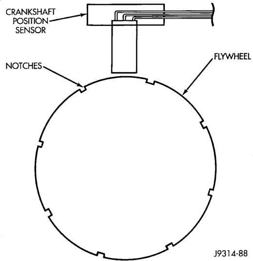
On 5.2L/5.9L V-8 engines, the flywheel/drive plate has 8 single notches, spaced every 45 degrees, at its outer edge (Fig. 3).
The notches cause a pulse to be generated when they pass under the sensor. The pulses are the input to the PCM. For each engine revolution, there are 8 pulses generated on V-8 engines.
The engine will not operate if the PCM does not receive a crankshaft position sensor input.
CRANKSHAFT POSITION SENSOR—4.0L ENGINE
Engine speed and crankshaft position are provided through the crankshaft position sensor. The sensor generates pulses that are the input sent to the powertrain control module (PCM). The PCM interprets the sensor input to determine the crankshaft position. The PCM then uses this position, along with other inputs, to determine injector sequence and ignition timing.
The sensor is a hall effect device combined with an internal magnet. It is also sensitive to steel within a certain distance from it.
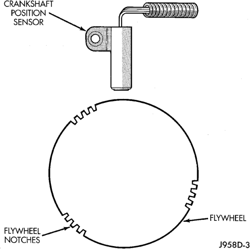
On 4.0L 6-cylinder engines, the flywheel/drive plate has 3 sets of four notches at its outer edge (Fig. 4).
The notches cause a pulse to be generated when they pass under the sensor. The pulses are the input to the PCM. For each engine revolution there are 3 sets of four pulses generated.
The trailing edge of the fourth notch, which causes the pulse, is four degrees before top dead center (TDC) of the corresponding piston.
The engine will not operate if the PCM does not receive a crankshaft position sensor input.
CAMSHAFT POSITION SENSOR
The camshaft position sensor is located in the distributor on all engines.
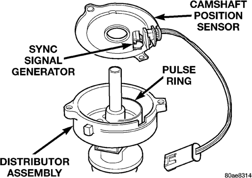
The sensor contains a hall effect device called a sync signal generator to generate a fuel sync signal. This sync signal generator detects a rotating pulse ring (shutter) on the distributor shaft. The pulse ring rotates 180 degrees through the sync signal generator. Its signal is used in conjunction with the crankshaft position sensor to differentiate between fuel injection and spark events. It is also used to synchronize the fuel injectors with their respective cylinders.
When the leading edge of the pulse ring (shutter) enters the sync signal generator, the following occurs: The interruption of magnetic field causes the voltage to switch high resulting in a sync signal of approximately 5 volts.
When the trailing edge of the pulse ring (shutter) leaves the sync signal generator, the following occurs: The change of the magnetic field causes the sync signal voltage to switch low to 0 volts.
MANIFOLD ABSOLUTE PRESSURE (MAP) SENSOR
For an operational description, diagnosis and removal/installation procedures, refer to Group 14, Fuel System.
ENGINE COOLANT TEMPERATURE SENSOR
For an operational description, diagnosis and removal/installation procedures, refer to Group 14, Fuel System.
THROTTLE POSITION SENSOR
For an operational description, diagnosis and removal/installation procedures, refer to Group 14, Fuel System.
INTAKE MANIFOLD AIR TEMPERATURE SENSOR
For an operational description, diagnosis and removal/installation procedures, refer to Group 14, Fuel System.
IGNITION SWITCH AND KEY LOCK CYLINDER
The ignition switch is located on the steering column. The Key-In-Switch is located in the ignition switch module. For electrical diagnosis of the Key-In- Switch, refer to Group 8U, Chime/Buzzer Warning Systems. For removal/installation of either the key lock cylinder or ignition switch, refer to Ignition Switch and Key Cylinder Removal/Installation in this group.
On vehicles equipped with an automatic transmission, a cable connects an interlock device within the steering column assembly to the transmission floor shift lever. This interlock device is used to lock the transmission shifter in the PARK position when the key is in the LOCKED or ACCESSORY position. The interlock device is not serviceable. If repair is necessary, the steering column assembly must be replaced. Refer to Group 19, Steering for procedures. The shifter interlock cable can be adjusted or replaced. Refer to Group 21, Transmissions for procedures.
DIAGNOSIS AND TESTING
AUTOMATIC SHUTDOWN (ASD) RELAY TEST
To perform a complete test of this relay and its circuitry, refer to the DRB scan tool. Also refer to the appropriate Powertrain Diagnostics Procedures manual. To test the relay only, refer to Relays—Operation/Testing in the Group 14, Fuel Systems section.
TESTING FOR SPARK AT COIL
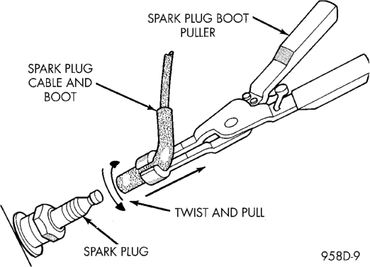
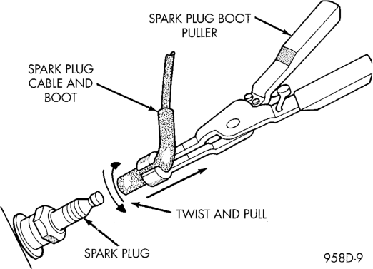
CAUTION: When disconnecting a high voltage cable from a spark plug or from the distributor cap, twist the rubber boot slightly (1/2 turn) to break it loose (Fig. 5). Grasp the boot (not the cable) and pull it off with a steady, even force.
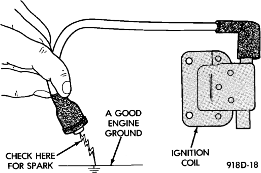
(1) Disconnect the ignition coil secondary cable from center tower of the distributor cap. Hold the cable terminal approximately 12 mm (1/2 in.) from a good engine ground (Fig. 6).
WARNING: BE VERY CAREFUL WHEN THE ENGINE IS CRANKING. DO NOT PUT YOUR HANDS NEAR THE PULLEYS, BELTS OR THE FAN. DO NOT WEAR LOOSE FITTING CLOTHING.
(2) Rotate (crank) the engine with the starter motor and observe the cable terminal for a steady arc. If steady arcing does not occur, inspect the secondary coil cable. Refer to Spark Plug Cables in this group. Also inspect the distributor cap and rotor for cracks or burn marks. Repair as necessary. If steady arcing occurs, connect ignition coil cable to the distributor cap.
(3) Remove a cable from one spark plug. (4) Using insulated pliers, hold the cable terminal approximately 12 mm (1/2 in.) from the engine cylinder head or block while rotating the engine with the starter motor. Observe the spark plug cable terminal for an arc. If steady arcing occurs, it can be expected that the ignition secondary system is operating correctly. (If the ignition coil cable is removed for this test, instead of a spark plug cable, the spark intensity will be much higher). If steady arcing occurs at the spark plug cables, but the engine will not start, connect the DRB scan tool. Refer to the appropriate Powertrain Diagnostic Procedures service manual.
IGNITION COIL TEST
To perform a complete test of the ignition coil and its circuitry, refer to the DRB scan tool. Also refer to the appropriate Powertrain Diagnostics Procedures manual. To test the coil only, refer to the following:
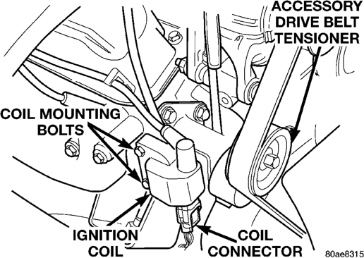
The ignition coil (Fig. 7) is designed to operate without an external ballast resistor.
IGNITION COIL RESISTANCE
COIL MANUFACTURER PRIMARY RESISTANCE 21-27°C
(70-80°F)
Diamond 0.97 - 1.18 Ohms 11,300 - 15,300 Ohms
Toyodenso 0.95 - 1.20 Ohms 11,300 - 13,300 Ohms
Inspect the ignition coil for arcing. Test the coil according to coil tester manufacturer's instructions. Test the coil primary and secondary resistance. Replace any coil that does not meet specifications. Refer to the IGNITION COIL RESISTANCE chart.
If the ignition coil is being replaced, the secondary spark plug cable must also be checked. Replace cable if it has been burned or damaged. Arcing at the tower will carbonize the cable boot, which if it is connected to a new ignition coil, will cause the coil to fail.
If the secondary coil cable shows any signs of damage, it should be replaced with a new cable and new terminal. Carbon tracking on the old cable can cause arcing and the failure of a new ignition coil.
FAILURE TO START TEST
To prevent unnecessary diagnostic time and wrong test results, the Testing For Spark At Coil test should be performed prior to this test.
WARNING: SET PARKING BRAKE OR BLOCK THE DRIVE WHEELS BEFORE PROCEEDING WITH THIS TEST.
(1) Unplug the ignition coil harness connector at the coil.
(2) Connect a set of small jumper wires (18 gauge or smaller) between the disconnected harness terminals and the ignition coil terminals. To determine polarity at connector and coil, refer to the Wiring Diagrams section.
(3) Attach one lead of a voltmeter to the positive (12 volt) jumper wire. Attach the negative side of voltmeter to a good ground. Determine that sufficient battery voltage (12.4 volts) is present for the starting and ignition systems.
(4) Determine that sufficient battery voltage (12.4 volts) is present for the starting and ignition systems.
(5) Crank the engine for 5 seconds while monitoring the voltage at the coil positive terminal: • If the voltage remains near zero during the entire period of cranking, refer to On-Board Diagnostics in Group 14, Fuel Systems. Check the Powertrain Control Module (PCM) and auto shutdown relay.
• If voltage is at or near battery voltage and drops to zero after 1-2 seconds of cranking, check the pow-
SECONDARY RESISTANCE
21-27°C (70-80°F)
ertrain control module circuit. Refer to On-Board Diagnostics in Group 14, Fuel Systems.
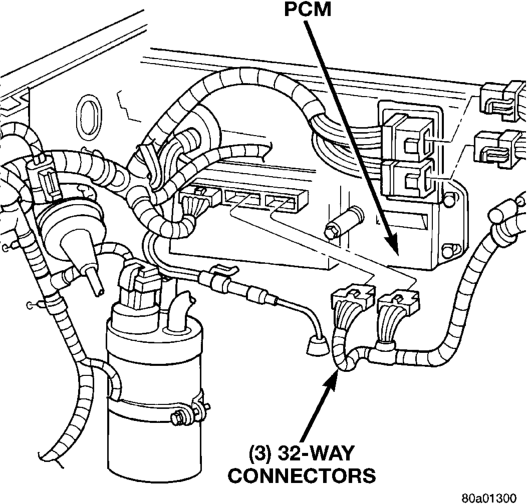
• If voltage remains at or near battery voltage during the entire 5 seconds, turn the key off. Remove the three 32-way connectors (Fig. 8) from the PCM. Check 32-way connectors for any spread terminals or corrosion.
(6) Remove test lead from the coil positive terminal. Connect an 18 gauge jumper wire between the battery positive terminal and the coil positive terminal.
(7) Make the special jumper shown in (Fig. 9). Using the jumper, momentarily ground the ignition coil driver circuit at the PCM connector (cavity A-7). For cavity/terminal location of this circuit, refer to Group 8W, Wiring. A spark should be generated at the coil cable when the ground is removed.
(8) If spark is generated, replace the PCM. (9) If spark is not seen, use the special jumper to ground the coil negative terminal directly.
(10) If spark is produced, repair wiring harness for an open condition.
(11) If spark is not produced, replace the ignition coil.
Terminal
DISTRIBUTOR CAP
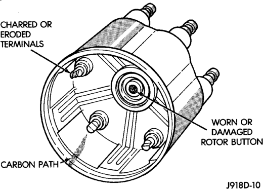
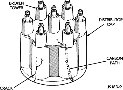
Remove the distributor cap and wipe it clean with a dry lint free cloth. Visually inspect the cap for cracks, carbon paths, broken towers or damaged rotor button (Fig. 10) or (Fig. 11). Also check for white deposits on the inside (caused by condensation entering the cap through cracks). Replace any cap that displays charred or eroded terminals. The machined surface of a terminal end (faces toward rotor) will indicate some evidence of erosion from normal operation. Examine the terminal ends for evidence of mechanical interference with the rotor tip.
DISTRIBUTOR ROTOR
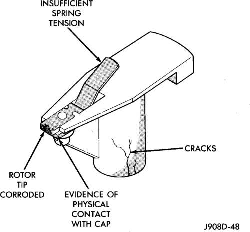
Visually inspect the rotor (Fig. 12) for cracks, evidence of corrosion or the effects of arcing on the metal tip. Also check for evidence of mechanical interference with the cap. Some charring is normal on the end of the metal tip. The silicone-dielectricvarnish-compound applied to the rotor tip for radio interference noise suppression, will appear charred. This is normal. Do not remove the charred compound. Test the spring for insufficient tension. Replace a rotor that displays any of these adverse conditions.
IGNITION TIMING
NOTE: Base (initial) ignition timing is NOT adjustable on any 4.0L/5.2L/5.9L engine. Do not attempt to adjust ignition timing by rotating the distributor.
NOTE: On 4.0L 6–cylinder engines, do not attempt to modify the slotted fork on the distributor housing to get distributor rotation. Distributor position will have no effect on ignition timing.
All ignition timing functions are controlled by the powertrain control module (PCM). For additional information, refer to the appropriate Powertrain Diagnostics Procedures service manual for operation of the DRB Scan Tool.
MAP SENSOR
For an operational description, diagnosis or removal/ installation procedures, refer to Group 14, Fuel Systems.
CRANKSHAFT POSITION SENSOR
To perform a complete test of this sensor and its circuitry, refer to the DRB scan tool. Also refer to the appropriate Powertrain Diagnostics Procedures manual.
CAMSHAFT POSITION SENSOR
The camshaft position sensor is located in the distributor (Fig. 13) on all engines.
(5.2L/5.9L Distributor Shown)
To perform a complete test of this sensor and its circuitry, refer to the appropriate Powertrain Diagnostics Procedures service manual. To test the sensor only, refer to the following:
For this test, an analog (non-digital) voltmeter is needed. Do not remove the distributor connector from the distributor. Using small paper clips, insert them into the backside of the distributor wire harness connector to make contact with the terminals. Be sure that the connector is not damaged when inserting the paper clips. Attach voltmeter leads to these paper clips.
(1) Connect the positive (+) voltmeter lead into the sensor output wire. This is at done the distributor wire harness connector. For wire identification, refer to Group 8W, Wiring Diagrams.
(2) Connect the negative (-) voltmeter lead into the ground wire. For wire identification, refer to Group 8W, Wiring Diagrams.
(3) Set the voltmeter to the 15 Volt DC scale. (4) 5.2L/5.9L Engines: Remove distributor cap from distributor (two screws). Rotate (crank) the engine until the distributor rotor is pointed towards the rear of vehicle. The movable pulse ring should now be within the sensor pickup.
(5) 4.0L Engine: Remove distributor cap from distributor (two screws). Rotate (crank) the engine until the distributor rotor is pointed to approximately the 11 o'clock position. The movable pulse ring should now be within the sensor pickup.
(6) Turn ignition key to ON position. Voltmeter should read approximately 5.0 volts.
(7) If voltage is not present, check the voltmeter leads for a good connection.
(8) If voltage is still not present, check for voltage at the supply wire. For wire identification, refer to Group 8W, Wiring Diagrams.
(9) If 5 volts is not present at supply wire, check for voltage at PCM 32-way connector (cavity A-17). Refer to Group 8W, Wiring for location of connector/ terminal. Leave the PCM connector connected for this test.
(10) If voltage is still not present, perform vehicle test using the DRB scan tool.
(11) If voltage is present at cavity A-17, but not at the supply wire:
(a) Check continuity between the supply wire. This is checked between the distributor connector and cavity A-17 at the PCM. If continuity is not present, repair the harness as necessary.
(b) Check for continuity between the camshaft position sensor output wire and cavity A-18 at the PCM. If continuity is not present, repair the harness as necessary.
(c) Check for continuity between the ground circuit wire at the distributor connector and ground. If continuity is not present, repair the harness as necessary. (12) While observing the voltmeter, crank the engine with ignition switch. The voltmeter needle should fluctuate between 0 and 5 volts while the engine is cranking. This verifies that the camshaft position sensor in the distributor is operating properly and a sync pulse signal is being generated.
If sync pulse signal is not present, replacement of the camshaft position sensor is necessary
ENGINE COOLANT TEMPERATURE SENSOR
For an operational description, diagnosis and removal/installation procedures, refer to Group 14, Fuel System.
INTAKE MANIFOLD AIR TEMPERATURE SENSOR
For an operational description, diagnosis and removal/installation procedures, refer to Group 14, Fuel System.
SPARK PLUG CABLES
Check the spark plug cable connections for good contact at the coil(s), distributor cap towers, and spark plugs. Terminals should be fully seated. The insulators should be in good condition and should fit tightly on the coil, distributor and spark plugs. Spark plug cables with insulators that are cracked or torn must be replaced.
Clean high voltage ignition cables with a cloth moistened with a non-flammable solvent. Wipe the cables dry. Check for brittle or cracked insulation.
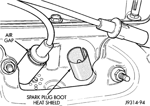
On 5.2L/5.9L V-8 engines, spark plug cable heat shields are pressed into the cylinder head to surround each spark plug cable boot and spark plug (Fig. 14). These shields protect the spark plug boots from damage (due to intense engine heat generated by the exhaust manifolds) and should not be removed. After the spark plug cable has been installed, the lip of the cable boot should have a small air gap to the top of the heat shield (Fig. 14).
TESTING
When testing secondary cables for damage with an oscilloscope, follow the instructions of the equipment manufacturer.
If an oscilloscope is not available, spark plug cables may be tested as follows:
CAUTION: Do not leave any one spark plug cable disconnected for longer than necessary during testing. This may cause possible heat damage to the catalytic converter. Total test time must not exceed ten minutes.
With the engine running, remove spark plug cable from spark plug (one at a time) and hold next to a good engine ground. If the cable and spark plug are in good condition, the engine rpm should drop and the engine will run poorly. If engine rpm does not drop, the cable and/or spark plug may not be operating properly and should be replaced. Also check engine cylinder compression.
With the engine not running, connect one end of a test probe to a good ground. Start the engine and run the other end of the test probe along the entire length of all spark plug cables. If cables are cracked or punctured, there will be a noticeable spark jump from the damaged area to the test probe. The cable running from the ignition coil to the distributor cap can be checked in the same manner. Cracked, damaged or faulty cables should be replaced with resistance type cable. This can be identified by the words ELECTRONIC SUPPRESSION printed on the cable jacket.
Use an ohmmeter to test for open circuits, excessive resistance or loose terminals. If equipped, remove the distributor cap from the distributor. Do not remove cables from cap. Remove cable from spark plug. Connect ohmmeter to spark plug terminal end of cable and to corresponding electrode in distributor cap. Resistance should be 250 to 1000 Ohms per inch of cable. If not, remove cable from distributor cap tower and connect ohmmeter to the terminal ends of cable. If resistance is not within specifications as found in the SPARK PLUG CABLE RESISTANCE chart, replace the cable. Test all spark plug cables in this manner.
SPARK PLUG CABLE RESISTANCE
MINIMUM MAXIMUM
250 Ohms Per Inch 1000 Ohms Per Inch
3000 Ohms Per Foot 12,000 Ohms Per Foot
To test ignition coil-to-distributor cap cable, do not remove the cable from the cap. Connect ohmmeter to rotor button (center contact) of distributor cap and terminal at ignition coil end of cable. If resistance is not within specifications as found in the Spark Plug Cable Resistance chart, remove the cable from the distributor cap. Connect the ohmmeter to the terminal ends of the cable. If resistance is not within specifications as found in the Spark Plug Cable Resistance chart, replace the cable. Inspect the ignition coil tower for cracks, burns or corrosion.
SPARK PLUG CONDITIONS
NORMAL OPERATING
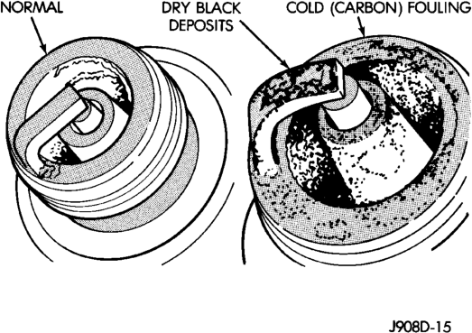
The few deposits present on the spark plug will probably be light tan or slightly gray in color. This is evident with most grades of commercial gasoline (Fig. 15). There will not be evidence of electrode burning. Gap growth will not average more than approximately 0.025 mm (.001 in) per 1600 km (1000 miles) of operation. Spark plugs that have normal wear can usually be cleaned, have the electrodes filed, have the gap set and then be installed.
Some fuel refiners in several areas of the United States have introduced a manganese additive (MMT) for unleaded fuel. During combustion, fuel with MMT causes the entire tip of the spark plug to be coated with a rust colored deposit. This rust color can be misdiagnosed as being caused by coolant in the combustion chamber. Spark plug performance is not affected by MMT deposits.
COLD FOULING/CARBON FOULING
Cold fouling is sometimes referred to as carbon fouling. The deposits that cause cold fouling are basically carbon (Fig. 15). A dry, black deposit on one or two plugs in a set may be caused by sticking valves or defective spark plug cables. Cold (carbon) fouling of the entire set of spark plugs may be caused by a clogged air cleaner element or repeated short operating times (short trips).
WET FOULING OR GAS FOULING
A spark plug coated with excessive wet fuel or oil is wet fouled. In older engines, worn piston rings, leaking valve guide seals or excessive cylinder wear can cause wet fouling. In new or recently overhauled engines, wet fouling may occur before break-in (normal oil control) is achieved. This condition can usually be resolved by cleaning and reinstalling the fouled plugs.
OIL OR ASH ENCRUSTED
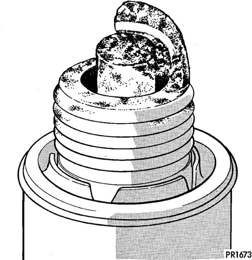
If one or more spark plugs are oil or oil ash encrusted (Fig. 16), evaluate engine condition for the cause of oil entry into that particular combustion chamber.
ELECTRODE GAP BRIDGING
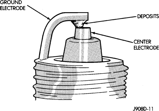
Electrode gap bridging may be traced to loose deposits in the combustion chamber. These deposits accumulate on the spark plugs during continuous stop-and-go driving. When the engine is suddenly subjected to a high torque load, deposits partially liquefy and bridge the gap between electrodes (Fig. 17). This short circuits the electrodes. Spark plugs with electrode gap bridging can be cleaned using standard procedures.
SCAVENGER DEPOSITS
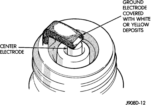
Fuel scavenger deposits may be either white or yellow (Fig. 18). They may appear to be harmful, but this is a normal condition caused by chemical additives in certain fuels. These additives are designed to change the chemical nature of deposits and decrease spark plug misfire tendencies. Notice that accumulation on the ground electrode and shell area may be heavy, but the deposits are easily removed. Spark plugs with scavenger deposits can be considered normal in condition and can be cleaned using standard procedures.
CHIPPED ELECTRODE INSULATOR
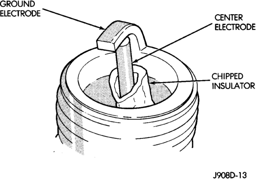
A chipped electrode insulator usually results from bending the center electrode while adjusting the spark plug electrode gap. Under certain conditions, severe detonation can also separate the insulator from the center electrode (Fig. 19). Spark plugs with this condition must be replaced.
PREIGNITION DAMAGE
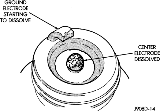
Preignition damage is usually caused by excessive combustion chamber temperature. The center electrode dissolves first and the ground electrode dissolves somewhat latter (Fig. 20). Insulators appear relatively deposit free. Determine if the spark plug has the correct heat range rating for the engine.
Determine if ignition timing is over advanced or if other operating conditions are causing engine overheating. (The heat range rating refers to the operating temperature of a particular type spark plug. Spark plugs are designed to operate within specific temperature ranges. This depends upon the thickness and length of the center electrodes porcelain insulator.)
SPARK PLUG OVERHEATING
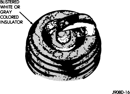
Overheating is indicated by a white or gray center electrode insulator that also appears blistered (Fig. 21). The increase in electrode gap will be considerably in excess of 0.001 inch per 1000 miles of operation. This suggests that a plug with a cooler heat range rating should be used. Over advanced ignition timing, detonation and cooling system malfunctions can also cause spark plug overheating.
REMOVAL AND INSTALLATION
SPARK PLUG CABLES
CAUTION: When disconnecting a high voltage cable from a spark plug or from the distributor cap, twist the rubber boot slightly (1/2 turn) to break it loose (Fig. 22). Grasp the boot (not the cable) and pull it off with a steady, even force.
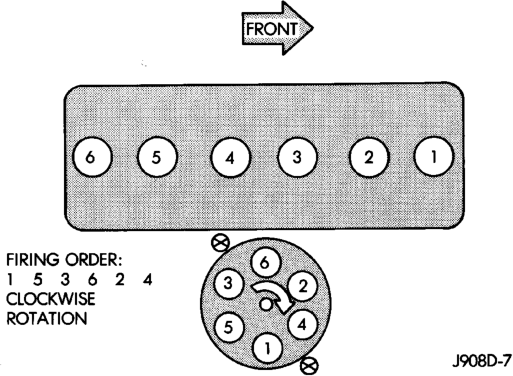
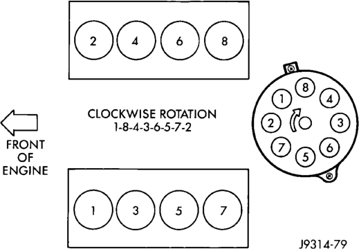
Install cables into the proper engine cylinder firing order (Fig. 23) or (Fig. 24).
When replacing the spark plug and coil cables, route the cables correctly and secure in the proper retainers. Failure to route the cables properly can cause the radio to reproduce ignition noise. It could also cause cross ignition of the plugs or short circuit the cables to ground.
When installing new cables, make sure a positive connection is made. A snap should be felt when a
good connection is made between the plug cable and the distributor cap tower.
SPARK PLUGS
On 5.2L/5.9L V-8 engines, spark plug cable heat shields are pressed into the cylinder head to surround each cable boot and spark plug (Fig. 25).
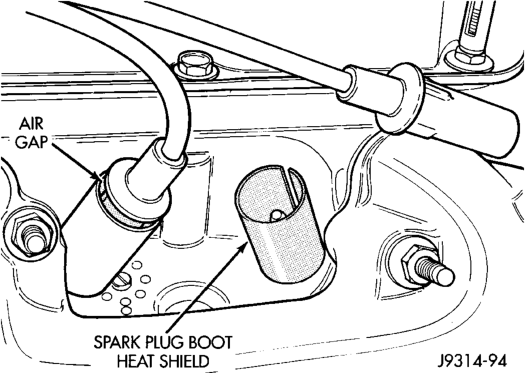
If removal of the heat shield(s) is necessary, remove the spark plug cable and compress the sides of shield for removal. Each shield is slotted to allow for compression and removal. To install the shields, align shield to machined opening in cylinder head and tap into place with a block of wood.
PLUG REMOVAL
(1) Always remove spark plug or ignition coil cables by grasping at the cable boot (Fig. 22). Turn the cable boot 1/2 turn and pull straight back in a steady motion. Never pull directly on the cable. Internal damage to cable will result.
(2) Prior to removing the spark plug, spray compressed air around the spark plug hole and the area around the spark plug. This will help prevent foreign material from entering the combustion chamber.
(3) Remove the spark plug using a quality socket with a rubber or foam insert.
(4) Inspect the spark plug condition. Refer to Spark Plug Condition in the Diagnostics and Testing section of this group.
PLUG CLEANING
The plugs may be cleaned using commercially available spark plug cleaning equipment. After cleaning, file the center electrode flat with a small point file or jewelers file before adjusting gap.
CAUTION: Never use a motorized wire wheel brush to clean the spark plugs. Metallic deposits will remain on the spark plug insulator and will cause plug misfire.
PLUG GAP ADJUSTMENT
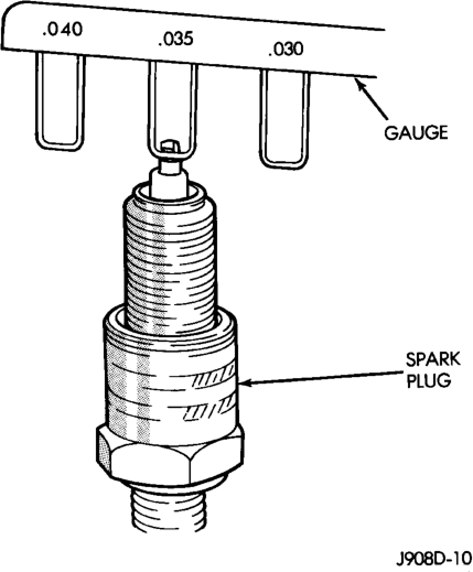
Check the spark plug gap with a gap gauge tool. If the gap is not correct, adjust it by bending the ground electrode (Fig. 26). Never attempt to adjust the gap by bending the center electrode.
SPARK PLUG GAP
4.0L 6–Cyl. Engine: .89 mm (.035 in). 5.2/5.9L V-8 Engines: 1.01 mm (.040 in).
PLUG INSTALLATION
Special care should be taken when installing spark plugs into the cylinder head spark plug wells. Be sure the plugs do not drop into the plug wells as electrodes can be damaged.
Always tighten spark plugs to the specified torque. Over tightening can cause distortion resulting in a change in the spark plug gap or a cracked porcelain insulator. When replacing the spark plug and ignition coil cables, route the cables correctly and secure them in the appropriate retainers. Failure to route the cables properly can cause the radio to reproduce ignition noise. It could cause cross ignition of the spark plugs or short circuit the cables to ground.
(1) Start the spark plug into the cylinder head by hand to avoid cross threading.
(2) Tighten spark plugs to 35-41 N·m (26-30 ft. lbs.) torque.
(3) Install spark plug cables over spark plugs.
IGNITION COIL—5.2L/5.9L ENGINES
The ignition coil is an epoxy filled type. If the coil is replaced, it must be replaced with the same type.
REMOVAL
The coil is mounted to a bracket that is bolted to the front of the right engine cylinder head (Fig. 27). This bracket is mounted on top of the automatic belt tensioner bracket using common bolts.
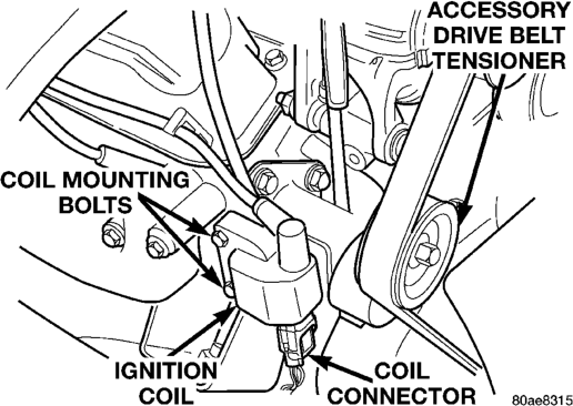
(1) Disconnect the primary wiring from the ignition coil.
(2) Disconnect the secondary spark plug cable from the ignition coil.
WARNING: DO NOT REMOVE THE COIL MOUNT- ING BRACKET-TO-CYLINDER HEAD MOUNTING BOLTS. THE COIL MOUNTING BRACKET IS UNDER ACCESSORY DRIVE BELT TENSION. IF THIS BRACKET IS TO BE REMOVED FOR ANY REASON, ALL BELT TENSION MUST FIRST BE RELIEVED. REFER TO THE BELT SECTION OF GROUP 7, COOLING SYSTEM.
(3) Remove ignition coil from coil mounting bracket (two bolts).
INSTALLATION
(1) Install the ignition coil to coil bracket. If nuts and bolts are used to secure coil to coil bracket, tighten to 11 N·m (100 in. lbs.) torque. If the coil mounting bracket has been tapped for coil mounting bolts, tighten bolts to 5 N·m (50 in. lbs.) torque.
(2) Connect all wiring to ignition coil.
IGNITION COIL—4.0L ENGINE
The ignition coil is an epoxy filled type. If the coil is replaced, it must be replaced with the same type.
REMOVAL
The ignition coil is mounted to a bracket on the side of the engine to the front of the distributor (Fig. 28).
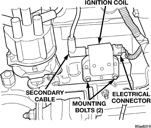
(1) Disconnect the ignition coil secondary cable from ignition coil (Fig. 28).
(2) Disconnect engine harness connector from ignition coil.
(3) Remove ignition coil mounting bolts (nuts may also be used on back side of bracket).
(4) Remove coil.
INSTALLATION
(1) Install ignition coil to bracket. If nut and bolts are used to secure coil to coil bracket, tighten to 11 N·m (100 in. lbs.) torque. If bolts are used, tighten bolts to 5 N·m (50 in. lbs.) torque.
(2) Connect engine harness connector to coil. (3) Connect ignition coil cable to ignition coil.
AUTOMATIC SHUTDOWN (ASD) RELAY
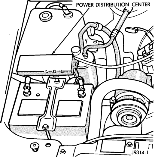
The Automatic Shutdown (ASD) relay is located in the Power Distribution Center (PDC). The PDC is located in the engine compartment (Fig. 29). Refer to label on PDC cover for relay location.
REMOVAL
(1) Remove PDC cover. (2) Remove relay by lifting straight up.
INSTALLATION
(1) Check condition of relay terminals at PDC for corrosion or damage. Also check the heights of relay terminal pins at PDC. Pin height should be same for all pins. Repair as necessary before installing relay.
(2) Push relay into connector. (3) Install relay cover.
CRANKSHAFT POSITION SENSOR—5.2L/5.9L ENGINES
REMOVAL
The sensor is bolted to the top of the cylinder block near the rear of right cylinder head (Fig. 30).
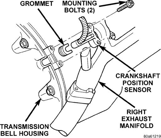
Engines
(1) Disconnect crankshaft position sensor pigtail harness (3–way connector) from main wiring harness.
(2) Remove two sensor (recessed hex head) mounting bolts (Fig. 30). (3) Remove sensor from engine.
INSTALLATION
(1) Position crankshaft position sensor to engine. (2) Install mounting bolts and tighten to 8 N·m (70 in. lbs.) torque. (3) Connect main harness electrical connector to sensor.
CRANKSHAFT POSITION SENSOR—4.0L ENGINE
The crankshaft position sensor is mounted to the transmission bellhousing at the left/rear side of the engine block (Fig. 31). The sensor is adjustable and is attached with one bolt. A wire shield/router is attached to the sensor (Fig. 31).
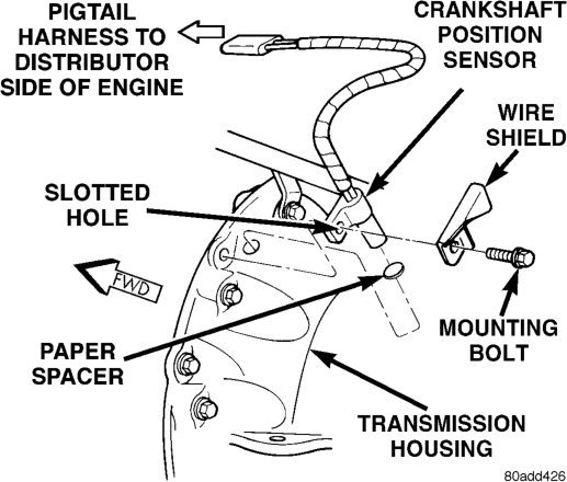
Engine
REMOVAL
(1) Disconnect sensor pigtail harness (3–way connector) from main engine wiring harness. This connection is made near rear of distributor.
(2) Remove sensor mounting bolt. (3) Remove wire shield and sensor.
INSTALLATION
4.0L engines with automatic transmission: New replacement sensors will be equipped with a paper spacer glued to bottom of sensor. If installing (returning) a used sensor to vehicle, a new paper spacer must be installed to bottom of sensor. This spacer will be ground off the first time engine is started. If spacer is not used, sensor will be broken the first time engine is started.
(1) New Sensors: Be sure paper spacer is installed to bottom of sensor. If not, obtain spacer PN05252229.
(2) Used Sensors: Clean bottom of sensor and install spacer PN05252229. (3) Install sensor into transmission bellhousing hole.
(4) Position sensor wire shield to sensor (Fig. 31). (5) Push sensor against flywheel/drive plate. With sensor pushed against flywheel/drive plate, tighten mounting bolt to 7 N·m (60 in. lbs.) torque.
(6) Route sensor wiring harness into wire shield. (7) Connect sensor pigtail harness electrical connector to main wiring harness.
CAMSHAFT POSITION SENSOR
The camshaft position sensor is located in the distributor on all 4.0L 6–cylinder and 5.2L/5.9L V-8 engines (Fig. 32).
REMOVAL
Distributor removal is not necessary to remove camshaft position sensor.
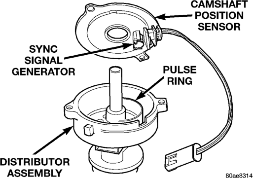
(5.2L/5.9L Shown)
(1) 5.2L/5.9L Engines: Remove air cleaner tube at throttle body.
(2) Disconnect negative cable from battery. (3) Remove distributor cap from distributor (two screws).
(4) Disconnect camshaft position sensor wiring harness from main engine wiring harness.
(5) Remove distributor rotor from distributor shaft. (6) Lift the camshaft position sensor assembly from the distributor housing (Fig. 32).
INSTALLATION
(1) Install camshaft position sensor to distributor. Align sensor into notch on distributor housing.
(2) Connect wiring harness. (3) Install rotor. (4) Install distributor cap. Tighten mounting screws.
(5) 5.2L/5.9L Engines: Install air cleaner tube to throttle body.
MANIFOLD ABSOLUTE PRESSURE (MAP) SENSOR
For removal and installation, refer to Manifold Absolute Pressure Sensor in group 14, Fuel Systems.
ENGINE COOLANT TEMPERATURE SENSOR
For an operational description, diagnosis and removal/installation procedures, refer to Group 14, Fuel System.
THROTTLE POSITION SENSOR
For an operational description, diagnosis and removal/installation procedures, refer to Group 14, Fuel System.
INTAKE MANIFOLD AIR TEMPERATURE SENSOR
For an operational description, diagnosis and removal/installation procedures, refer to Group 14, Fuel System.
DISTRIBUTOR—5.2L/5.9L ENGINES
REMOVAL
CAUTION: Base ignition timing is not adjustable on any 5.2L/5.9L V-8 engine. Distributors do not have built in centrifugal or vacuum assisted advance. Base ignition timing and timing advance are controlled by the Powertrain Control Module (PCM). Because a conventional timing light can not be used to adjust distributor position after installation, note position of distributor before removal.
(1) Disconnect negative cable from battery. (2) Remove air cleaner tube at throttle body. (3) Disconnect coil secondary cable at distributor cap.
(4) Disconnect all secondary spark plug cables at distributor cap. Note and mark position before removal.
(5) Remove distributor cap from distributor (two screws).
(6) Mark position of distributor housing in relationship to engine or dash panel. This is done to aid in installation. (7) Before distributor is removed, number one cylinder must be brought to Top Dead Center (TDC) firing position. (8) Attach a socket to Crankshaft Vibration Damper mounting bolt.
(9) Slowly rotate engine clockwise, as viewed from front, until indicating mark on crankshaft vibration damper is aligned to 0 degree (TDC) mark on timing chain cover (Fig. 33).
(10) The distributor rotor should now be aligned to CYL. NO. 1 alignment mark (stamped) into camshaft position sensor (Fig. 34). If not, rotate crankshaft through another complete 360 degree turn. Note position of number one cylinder spark plug cable (on the cap) in relation to rotor. Rotor should now be aligned to this position.
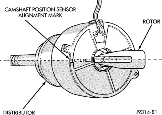
(11) Disconnect camshaft position sensor wiring harness 3–way connector from main engine wiring harness.
(12) Remove distributor rotor from distributor shaft.
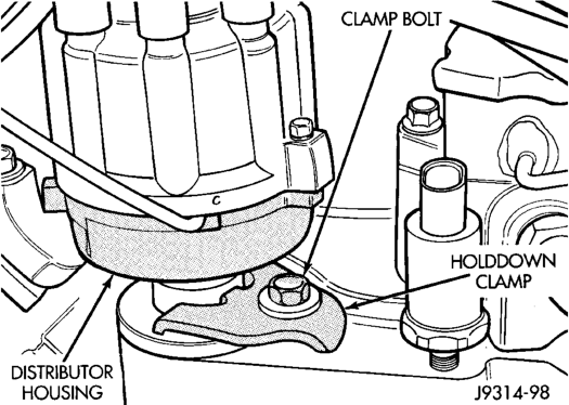
(13) Remove distributor holddown clamp bolt and clamp (Fig. 35).
(14) Remove distributor from vehicle.
CAUTION: Do not crank engine with distributor removed. Distributor/crankshaft relationship will be lost.
INSTALLATION
If engine has been cranked while distributor is removed, establish relationship between distributor shaft and number one piston position as follows:
Rotate crankshaft in a clockwise direction, as viewed from front, until number one cylinder piston is at top of compression stroke (compression should be felt on finger with number one spark plug
Engines
removed). Then continue to slowly rotate engine clockwise until indicating mark (Fig. 33) is aligned to 0 degree (TDC) mark on timing chain cover.
(1) Clean top of cylinder block for a good seal between distributor base and block.
(2) Lightly oil the rubber o-ring seal on distributor housing.
(3) Install rotor to distributor shaft. (4) Position distributor into engine to its original position. Engage tongue of distributor shaft with slot in distributor oil pump drive gear. Position rotor to number one spark plug cable position.
(5) Install distributor holddown clamp and clamp bolt. Do not tighten bolt at this time.
(6) Rotate distributor housing until rotor is aligned to CYL. NO. 1 alignment mark on camshaft position sensor (Fig. 34).
(7) Tighten clamp holddown bolt (Fig. 35) to 22.5 N·m (200 in. lbs.) torque.
(8) Connect camshaft position sensor wiring harness to main engine harness.
(9) Install distributor cap. Tighten mounting screws.
(10) Install secondary cables to distributor cap. (11) Refer to following, Checking Distributor Position.
CHECKING DISTRIBUTOR POSITION
To verify correct distributor rotational position, the DRB scan tool must be used.
WARNING: WHEN PERFORMING THE FOLLOWING TEST, THE ENGINE WILL BE RUNNING. BE CARE- FUL NOT TO STAND IN LINE WITH THE FAN BLADES OR FAN BELT. DO NOT WEAR LOOSE CLOTHING.
(1) Connect DRB scan tool to data link connector. The data link connector is located in passenger compartment, below and to left of steering column.
(2) Gain access to SET SYNC screen on DRB. (3) Follow directions on DRB screen and start engine. Bring to operating temperature (engine must be in “closed loop” mode).
(4) With engine running at idle speed, the words IN RANGE should appear on screen along with 0°. This indicates correct distributor position.
(5) If a plus (+) or a minus (-) is displayed next to degree number, and/or the degree displayed is not zero, loosen but do not remove distributor holddown clamp bolt. Rotate distributor until IN RANGE appears on screen. Continue to rotate distributor until achieving as close to 0° as possible. After adjustment, tighten clamp bolt to 22.5 N·m (200 in. lbs.) torque.
The degree scale on SET SYNC screen of DRB is referring to fuel synchronization only. It is not referring to ignition timing. Because of this, do not attempt to adjust ignition timing using this method. Rotating distributor will have no effect on ignition timing. All ignition timing values are controlled by powertrain control module (PCM).
(6) After testing, install air cleaner tube to throttle body.
DISTRIBUTOR—4.0L ENGINE
All 4.0L distributors contain an internal oil seal that prevents oil from entering the distributor housing. The seal is not serviceable. Factory replacement distributors are equipped with a plastic alignment pin already installed. The pin is located in an access hole on the bottom of the distributor housing (Fig. 36). It is used to temporarily lock the rotor to the cylinder number 1 position during installation. The pin must be removed after installing the distributor. The camshaft position sensor is located in the distributor on all 4.0L engines (Fig. 37). For removal/installation procedures, refer to Camshaft Position Sensor. Distributor removal is not necessary for sensor removal.
Refer to (Fig. 37) for an exploded view of distributor.
A fork with a slot is supplied on bottom of distributor housing where the housing base seats against engine block (Fig. 37). The centerline of the slot aligns with distributor holddown bolt hole in engine block. Because of the fork, the distributor cannot be rotated. Distributor rotation is not necessary as all ignition timing requirements are handled by the powertrain control module (PCM).
The position of distributor determines fuel synchronization only. It does not determine ignition timing.
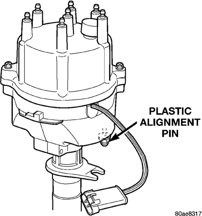
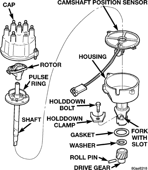
NOTE: Do not attempt to modify this fork to attain ignition timing.

(1) Disconnect negative battery cable at battery. (2) Disconnect coil secondary cable at coil. (3) Remove distributor cap from distributor (2 screws). Do not remove cables from cap. Do not remove rotor.
(4) Disconnect distributor wiring harness 3–way connector from main engine harness.
(5) Remove cylinder number 1 spark plug. (6) Hold a finger over the open spark plug hole. Rotate engine at vibration dampener bolt until compression (pressure) is felt.
(7) Slowly continue to rotate engine. Do this until timing index mark on vibration damper pulley aligns with top dead center (TDC) mark (0 degree) on timing degree scale (Fig. 38). Always rotate engine in direction of normal rotation. Do not rotate engine backward to align timing marks.
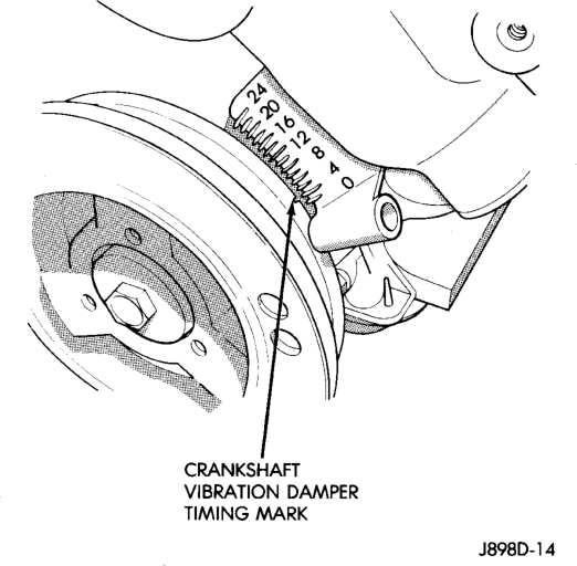
(8) Remove distributor holddown bolt and clamp. (9) Remove distributor from engine by slowly lifting straight up. (10) Note that rotor will rotate slightly in a counterclockwise direction while lifting up the distributor. The oil pump gear will also rotate slightly in a counterclockwise direction while lifting up the distributor. This is due to the helical cut gears on distributor and camshaft.
(11) Note removed position of rotor during distributor removal. During installation, this will be referred to as the Pre-position.
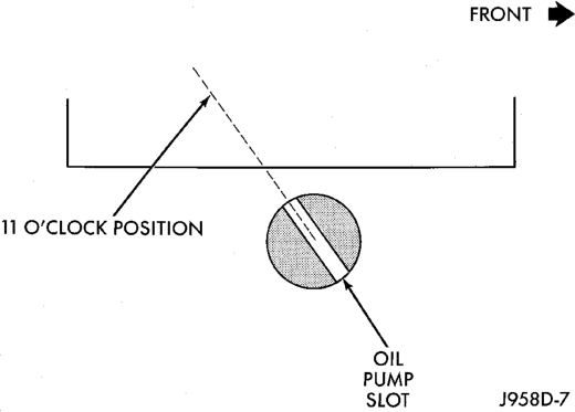
(12) Observe slot in oil pump gear through hole on side of engine. It should be slightly before (counterclockwise of) the 11 o'clock position (Fig. 39).
(13) Remove and discard old distributor-to-engine block gasket.
INSTALLATION
(1) If engine crankshaft has been rotated after distributor removal, cylinder number 1 must be returned to its proper firing stroke. Refer to previous REMOVAL Step 5 and Step 6. These steps must be done before installing distributor.
(2) Check position of slot on oil pump gear. It should be just slightly before (counterclockwise of) the 11 o'clock position (Fig. 39). If not, place a flat blade screwdriver into oil pump gear and rotate it into proper position. (3) Factory replacement distributors are equipped with a plastic alignment pin already installed (Fig. 36). This pin is used to temporarily hold rotor to cylinder number 1 firing position during distributor installation. If pin is in place, proceed to Step 8. If not, proceed to next step.
(4) If original distributor is to be reinstalled, such as during engine overhaul, the plastic pin will not be available. A 3/16 inch drift pin punch tool may be substituted for plastic pin.
(5) Remove camshaft position sensor from distributor housing. Lift straight up.
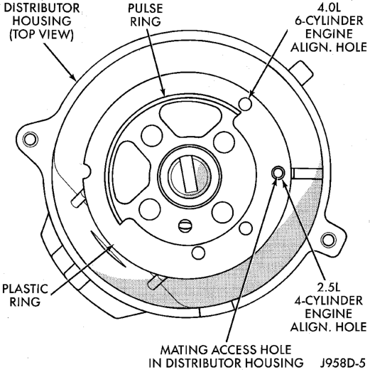
(6) Four different alignment holes are provided on the plastic ring (Fig. 40). Note that 2.5L and 4.0L engines have different alignment holes (Fig. 40).
(7) Rotate distributor shaft and install pin punch tool through proper alignment hole in plastic ring (Fig. 40) and into mating access hole in distributor housing. This will prevent distributor shaft and rotor from rotating.
(8) Clean distributor mounting hole area of engine block.
(9) Install new distributor-to-engine block gasket (Fig. 37).
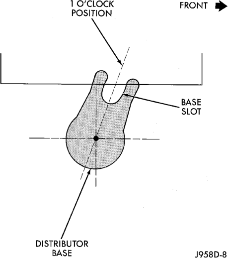
(10) Install rotor to distributor shaft. Pre-position distributor into engine while holding centerline of base slot in 1 o'clock position (Fig. 41). Continue to engage distributor into engine. The rotor and distributor will rotate clockwise during installation. This is due to the helical cut gears on distributor and camshaft. When distributor is fully seated to engine block, the centerline of base slot should be aligned to clamp bolt mounting hole on engine (Fig. 42). The rotor should also be pointed at 5 o'clock position.
It may be necessary to rotate rotor and distributor shaft (very slightly) to engage distributor shaft with slot in oil pump gear. The same may have to be done to engage distributor gear with camshaft gear.
The distributor is correctly installed when: • rotor is pointed at 5 o'clock position. • plastic alignment pin (or pin punch tool) is still installed to distributor. • number 1 cylinder piston is set at top dead center (TDC) (compression stroke).
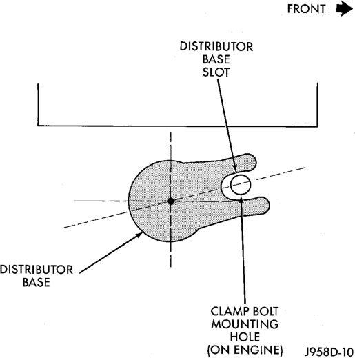
• centerline of the slot at base of distributor is aligned to centerline of distributor holddown bolt hole on engine. In this position, the holddown bolt should easily pass through slot and into engine.
No adjustments are necessary. Proceed to next step.
(11) Install distributor holddown clamp and bolt. Tighten bolt to 23 N·m (17 ft. lbs.) torque.
(12) Remove pin punch tool from distributor. Or, if plastic alignment pin was used, remove it straight down from bottom of distributor. Discard plastic pin.
(13) If removed, install camshaft position sensor to distributor. Align wiring harness grommet to notch in distributor housing.
(14) Install rotor.
CAUTION: If distributor cap is incorrectly positioned on distributor housing, the cap or rotor may be damaged when engine is started.
(15) Install distributor cap. Tighten distributor cap holddown screws to 3 N·m (26 in. lbs.) torque.
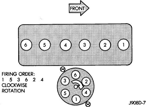
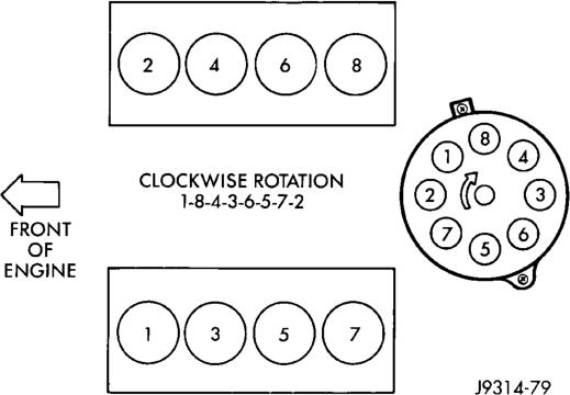
(16) If removed, install spark plug cables to distributor cap. For proper firing order, refer to Specifications section at end of this group. See Engine Firing Order.
(17) Connect distributor wiring harness to main engine harness.
(18) Connect battery cable to battery.
POWERTRAIN CONTROL MODULE (PCM)
Refer to Group 14, Fuel System for procedures.
IGNITION SWITCH AND KEY CYLINDER
The ignition key must be in the key cylinder for cylinder removal.
KEY CYLINDER REMOVAL
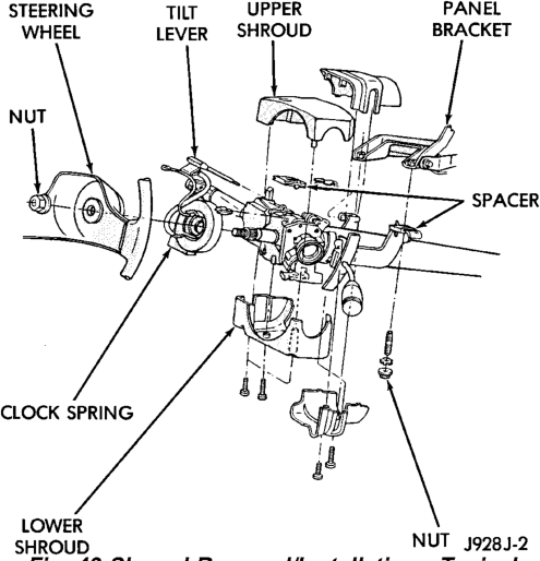
(1) Disconnect negative cable from battery. (2) If equipped with tilt column, remove tilt lever by turning it counterclockwise.
(3) Remove upper and lower covers (shrouds) from steering column (Fig. 43).
(4) If equipped with automatic transmission, place shifter in PARK position.
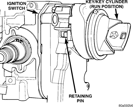
(5) A retaining pin (Fig. 44) is located at side of key cylinder assembly.
(a) Rotate key to RUN position. (b) Press in on retaining pin while pulling key cylinder from ignition switch.
IGNITION SWITCH REMOVAL
(1) Remove key lock cylinder. Refer to previous steps.
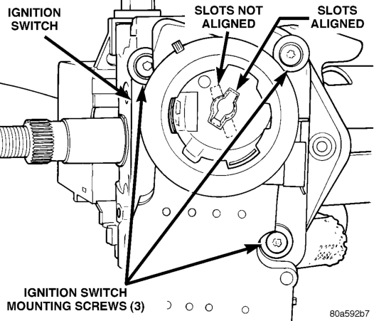
(2) Remove 3 ignition switch mounting screws (Fig. 45). Use tamper proof torx bit (Snap-Ont SDMTR10 or equivalent) to remove screws.
(3) Gently pull switch away from column. Release connector locks on 7-terminal wiring connector at ignition switch and remove connector (Fig. 46). (4) Release connector lock on 4-terminal halo lamp wiring connector and remove connector (Fig. 46).
IGNITION SWITCH AND KEY CYLINDER
INSTALLATION
If installing ignition key lock cylinder only, proceed to following steps 2, 3 and 4. Also refer to following steps 12 through 18. If installing both switch and key cylinder, refer to steps 1 through 18.
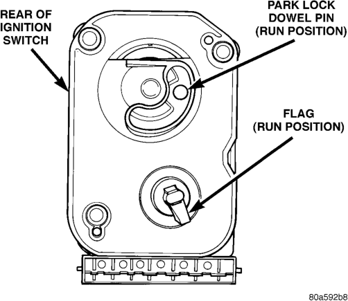
(1) Rotate flag (Fig. 47) on rear of ignition switch until in RUN position. This step must be done to allow tang (Fig. 48) on key cylinder to fit into slots (Fig. 45) within ignition switch.
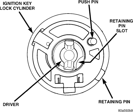
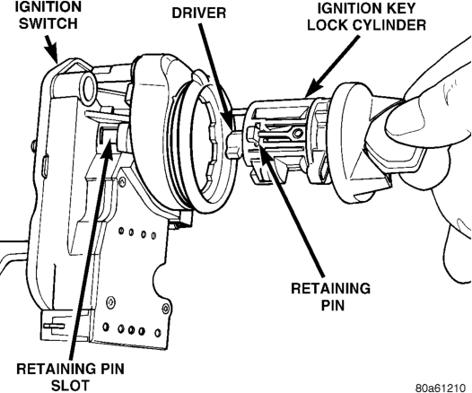
(2) With key into ignition key cylinder, rotate key clockwise until retaining pin can be depressed (Fig. 48) or (Fig. 49).
(3) Install key cylinder into ignition switch by aligning retaining pin into retaining pin slot (Fig. 49). Push key cylinder into switch until retaining pin engages. After pin engages, rotate key to OFF or LOCK position.
(4) Check for proper retention of key cylinder by attempting to pull cylinder from switch.
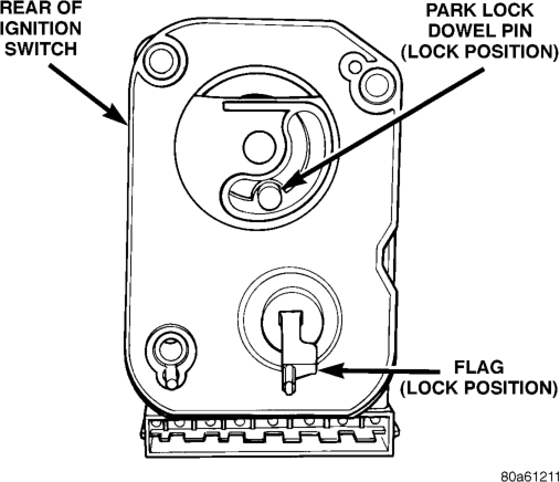
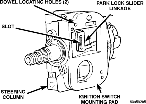
(5) Automatic Transmission Only: Before attaching ignition switch to steering column, the transmission shifter must be in PARK position. The park lock dowel pin on rear of ignition switch (Fig. 50) must also be properly indexed into the park lock linkage (Fig. 51) before installing switch.
(6) The flag at rear of ignition switch (Fig. 50) must be properly indexed into steering column before installing switch. This flag is used to operate the steering wheel lock lever in steering column (Fig. 52). This lever allows steering wheel position to be locked when key switch is in LOCK position.
(7) Place ignition switch in LOCK position. The switch is in the LOCK position when column lock flag is parallel to ignition switch terminals (Fig. 50).
Transmission—Typical
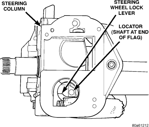
(8) Automatic Transmission Only: Apply a light coating of grease to park lock dowel pin and park lock slider linkage. Before installing switch, push the park lock slider linkage (Fig. 51) forward until it bottoms. Do a final positioning by pulling it rearward about one-quarter inch.
(9) Apply a light coating of grease to both column lock flag and shaft at end of flag.
(10) Place ignition switch into openings on steering column.
(a) Automatic Transmission Only: Be sure park lock dowel pin on rear of ignition switch enters slot in park lock slider linkage (Fig. 51). (b) Be sure flag on rear of switch is positioned above steering wheel lock lever (Fig. 52).
(c) Align dowel pins on rear of switch into holes on side of steering column.
(d) Install 3 ignition switch mounting screws. Tighten screws to 3 N·m 6 .5 N·m (26 in. lbs. 6 4 in. lbs.) torque. (11) Connect electrical connectors to ignition switch and halo lamp. Make sure that switch locking tabs are fully seated in wiring connectors.
(12) Install steering column covers (shrouds). Tighten screws to 2 N·m (17 in. lbs.) torque.
(13) Install tilt column lever (if equipped). (14) Connect negative cable to battery. (15) Check for proper operation of halo light. (16) Automatic Transmission Only: Shifter should lock in PARK position when key is in LOCK position (if equipped with shift lock device). Shifter should unlock when key rotated to ON position.
(17) Check for proper operation of ignition switch in ACCESSORY, LOCK, OFF, ON, RUN, and START positions.
(18)
Steering wheel should lock when key is in LOCK position. Rotate steering wheel to verify. Steering wheel should unlock when key is rotated to ON position.
SHIFTER/IGNITION INTERLOCK
On models equipped with an automatic transmission, a cable connects the ignition switch with the floor shift lever. The shifter will be locked in the PARK position when the ignition key is in the LOCK or ACCESSORY positions. The cable can be adjusted or replaced. Refer to Group 21, Transmissions for procedures. The ignition interlock device within the steering column is not serviceable. If service is necessary, the steering column must be replaced. Refer to Group 19, Steering for procedures.
SPECIFICATIONS
VECI LABEL
If anything differs between the specifications found on the Vehicle Emission Control Information (VECI) label and the following specifications, use specifications on VECI label. The VECI label is located in the engine compartment.
IGNITION TIMING
Ignition timing is not adjustable on any engine. Refer to Ignition Timing in the Diagnostics/Service Procedures section of this group for more information.
ENGINE FIRING ORDER—4.0L 6-CYLINDER ENGINE
ENGINE FIRING ORDER—5.2L/5.9L V-8 ENGINES
TORQUE CHART
DESCRIPTION TORQUE Crankshaft Position Sensor—
4.0L Engine . . . . . . . . . . . . . . . .7 N·m (60 in. lbs.) Crankshaft Position Sensor—
5.2L/5.9L Engine . . . . . . . . . . . .8 N·m (70 in. lbs.) Distributor Hold Down Bolt—
All Engines . . . . . . . . . . . . . . . .23 N·m (17 ft. lbs.) Ignition Coil Mounting
(if tapped bolts are used) . . . . . .5 N·m (50 in. lbs.) Ignition Coil Mounting
(if nuts/bolts are used) . . . . . .11 N·m (100 in. lbs.) Powertrain Control Module
(PCM) Mounting Screws . . . . . . .1 N·m (9 in. lbs.) Spark Plugs—All Engines. . . . . . .41 N·m (30 ft. lbs.)
IGNITION COIL RESISTANCE
COIL MANUFACTURER PRIMARY RESISTANCE 21-27°C
(70-80°F)
Diamond 0.97 - 1.18 Ohms 11,300 - 15,300 Ohms
Toyodenso 0.95 - 1.20 Ohms 11,300 - 13,300 Ohms
SPARK PLUGS
ENGINE PLUG TYPE ELECTRODE GAP
4.0L 6-CYL. RC12LYC 0.89 mm (.035 in.)
5.2/5.9L V-8 RC12LC4 1.01 mm (.040 in.)
SPARK PLUG CABLE RESISTANCE
MINIMUM MAXIMUM
250 Ohms Per Inch 1000 Ohms Per Inch
3000 Ohms Per Foot 12,000 Ohms Per Foot