Heating and Air Conditioning — part 2 of 2 — 1998 Jeep Grand Cherokee ZJ Export Service Manual
← Contents 1 2
Pages 1804–1807 · 4 pages · 2 words repaired
INSTALLATION
NOTE: If a replacement compressor is being installed, be certain to check the oil level. See Refrigerant Oil Level in this group.
(1) Install the compressor clutch and drive spool on the compressor as described in this group.
(2) Install the compressor on the engine block using the four mounting bolts and spacers. Tighten the bolts to 24 N·m (18 ft. lbs.).
(3) Install the bolts that secure the compressor clutch drive spool to the power steering pump drive flange. Tighten the bolts to 16 N·m (12 ft. lbs.).
(4) Lower the vehicle. (5) Remove the tape or plugs from all of the refrigerant fittings, and install the refrigerant lines on the compressor.
(6) Install the refrigerant line bracket on the engine valve cover. Tighten the bolt to 5.6 N·m (50 in. lbs.). (7) Plug in the compressor clutch coil wire harness connector.
(8) Connect the battery negative cable. (9) Evacuate and charge the refrigerant system as described in this group.
COMPRESSOR CLUTCH
GASOLINE ENGINE
The refrigerant system can remain fully-charged during compressor clutch, pulley, or coil replacement on gasoline engine models. The compressor clutch can be serviced in the vehicle.
REMOVAL
(1) Disconnect and isolate the battery negative cable.
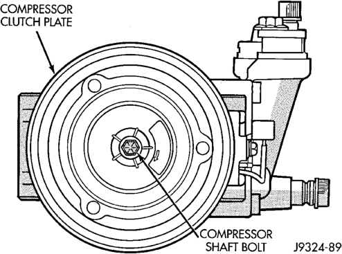
(2) Remove the compressor shaft bolt (Fig. 6). A band-type oil filter wrench may be used to aid in securing the clutch during bolt removal.
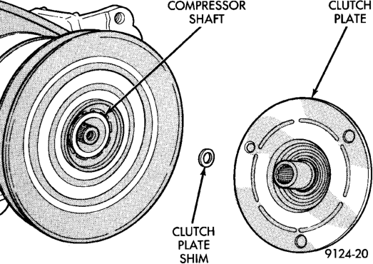
(3) Tap the clutch plate with a plastic mallet to release it from the splines on the compressor shaft. Remove clutch plate and shim(s) from the compressor shaft (Fig. 7).
CAUTION: Do not pry between the clutch plate assembly and the pulley to remove the front plate. This may damage the front plate assembly.
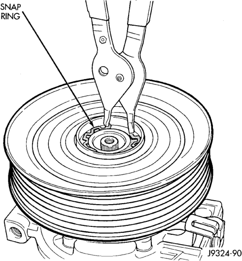
(4) Remove the pulley retaining snap ring with snap ring pliers (Special Tool C-4574) and slide the pulley assembly off of the compressor (Fig. 8).
(5) Unplug the clutch coil wire harness connector. Remove the screw and retainer from the clutch coil wire harness on the compressor front housing.
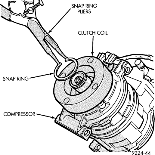
(6) Remove the snap ring from the compressor hub and remove the clutch field coil (Fig. 9). Slide the clutch field coil off of the compressor hub.
INSPECTION
Examine the friction surfaces of the clutch pulley and the front plate for wear. The pulley and front plate should be replaced if there is excessive wear or scoring.
If the friction surfaces are oily, inspect the shaft and nose area of the compressor for oil. Remove the felt from the front cover. If the felt is saturated with oil, the shaft seal is leaking and the compressor must be replaced.
Check the clutch pulley bearing for roughness or excessive leakage of grease. Replace the bearing, if required.
INSTALLATION
(1) Align the dowel pin on the back of the clutch field coil with the hole in the compressor front housing and press the field coil into place. (2) Install the clutch coil wire harness retaining clip on the compressor front housing and tighten the retaining screw. Plug in the clutch coil wire harness connector.
(3) Install the clutch field coil and snap ring with snap ring pliers (Special Tool C-4574). The bevel side of the snap ring must be facing outward. Also, both eyelets of the snap ring must be to the right or left of the pin on the compressor. Press the snap ring to make sure it is properly seated in the groove.
CAUTION: If the snap ring is not fully seated in the groove it will vibrate out, resulting in a clutch failure and severe damage to the front housing of the compressor.
(4) Install the pulley assembly onto the compressor. If necessary, place a block of wood on the friction surface and tap gently with a hammer (Fig. 10).
CAUTION: Do not mar the pulley friction surface.
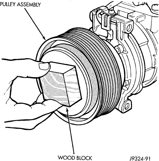
(5) Install the pulley assembly retaining snap ring (bevel side outward) with snap ring pliers (Special Tool C-4574). Press the snap ring to make sure it is properly seated in the groove.
(6) If the original front plate assembly and pulley assembly are to be reused, the old shim(s) can be used. If not, place a stack of shim(s) equal to the old shim(s) on the shaft against the shoulder.
(7) Install the front plate assembly onto the shaft. (8) With the front plate assembly tight against the shim(s), measure the air gap between the front plate and the pulley face with feeler gauges. The air gap should be 0.35 to 0.65 mm (0.014 to 0.026 in.). If the proper air gap is not obtained, add or subtract shims as needed until the desired air gap is obtained.
(9) Install the compressor shaft bolt. Tighten the bolt to 13 N·m (115 in. lbs.).
NOTE: The shims may compress after tightening the shaft bolt. Check the air gap in four or more places to verify the air gap is still correct. Spin the pulley before performing a final check of the air gap.
(10) Connect the battery negative cable.
CLUTCH BREAK-IN
After a new compressor clutch has been installed, cycle the compressor clutch approximately twenty times (five seconds on, then five seconds off). During this procedure, set the heater-A/C control to the A/C (Recirc) mode, the blower motor switch in the highest speed position, and the engine speed at 1500 to 2000 rpm. This procedure (burnishing) will seat the opposing friction surfaces and provide a higher compressor clutch torque capability.
DIESEL ENGINE
The refrigerant must be recovered from the refrigerant system during compressor clutch, drive, or coil replacement on diesel engine models. The compressor clutch cannot be serviced in the vehicle.
REMOVAL
(1) Remove the compressor and clutch from the vehicle as described in this group.
(2) Mount the compressor in a vise and remove the bolts that secure the drive spool to the drive plate.
(3) Remove the compressor drive plate with a spanner wrench (Special Tool 3281). Turn the drive plate counterclockwise to remove (Fig. 11).
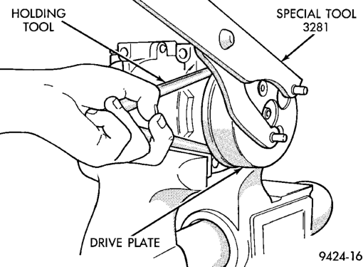
(4) Insert the two pins of the spanner wrench into two holes of the clutch plate. Hold the clutch plate stationary and remove the bolt that secures the clutch plate to the compressor shaft.
(5) Remove the clutch plate (Fig. 12).

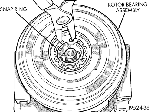
(6) Remove the external snap ring from the front compressor housing hub with snap ring pliers and remove the clutch rotor and bearing assembly (Fig. 13).
(7) Remove the screw and retainer from the clutch coil wire harness on the compressor front housing.
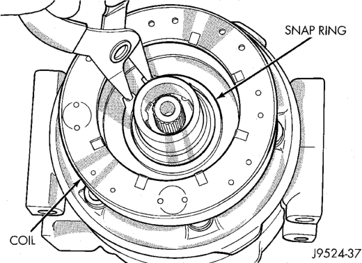
(8) Remove the snap ring from the compressor hub and remove the clutch field coil (Fig. 14). Slide the clutch field coil off of the compressor hub.
INSPECTION
Examine the friction surfaces of the clutch drive plate and the clutch plate for wear. The drive plate and clutch plate should be replaced if there is excessive wear or scoring.
If the friction surfaces are oily, inspect the shaft and nose area of the compressor for oil. Remove the felt from the front cover. If the felt is saturated with
oil, the shaft seal is leaking and the compressor must be replaced.
Check the clutch drive plate bearing for roughness or excessive leakage of grease. Replace the bearing, if required.
INSTALLATION
(1) Align the dowel pin on the back of the clutch field coil with the hole in the compressor front housing and press the field coil into place. (2) Install the clutch coil wire lead retaining clip on the compressor front housing and tighten the retaining screw.
(3) Install the clutch field coil and snap ring with snap ring pliers. The bevel side of the snap ring must be facing outward. Press the snap ring to make sure it is properly seated in the groove.
CAUTION: If the snap ring is not fully seated in the groove it will vibrate out, resulting in a clutch failure and severe damage to the front housing of the compressor.
(4) Check that the original clutch spacer shims are in place on the compressor shaft and install the clutch plate. Replace the shaft bolt and tighten to 14.4 N·m (10.5 ft. lbs.).
NOTE: The clutch air gap is determined by the spacer shims. When installing the original or a new clutch assembly, try the original shims first. When installing a new clutch onto a compressor that previously did not have a clutch, use 0.040, 0.020, and 0.005 in. shims from the clutch accessory sack.
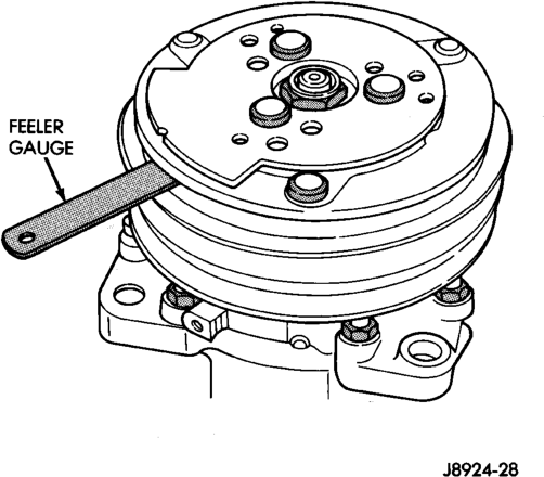
(5) Check the air gap with a feeler gauge (Fig. 15). If the air gap does not meet the specification add or subtract shims as required. The specification is 0.41 to 0.79 mm (0.016 to 0.031 inch). If the air gap is not consistent around the circumference, lightly pry up at the points of minimum variation. Lightly tap down at the points of maximum variation.
(6) Install the drive plate onto the clutch and tighten to 98 N·m (72 ft. lbs.).
(7) Install the drive spool onto the drive plate. Tighten the drive spool bolts to 16 N·m (12 ft. lbs.).
(8) Reverse the remaining removal procedures to complete the installation.
CLUTCH BREAK-IN
After a new compressor clutch has been installed, cycle the compressor clutch approximately twenty times (five seconds on, then five seconds off). During this procedure, set the heater-A/C control to the A/C (Recirc) mode, the blower motor switch in the highest speed position, and the engine speed at 1500 to 2000 rpm. This procedure (burnishing) will seat the opposing friction surfaces and provide a higher compressor clutch torque capability.