Fuel System — part 2 of 2 — 1998 Jeep Grand Cherokee ZJ Export Service Manual
← Contents 1 2
Pages 1291–1296 · 6 pages · 0 words repaired
(1) Raise and support vehicle. (2) Downstream Sensor Only: Disconnect O2S wiring connector clip (Fig. 81) at body. Remove clip from O2S electrical connector and discard.
(3) Disconnect O2S pigtail harness wire connector from main connector.
CAUTION: When disconnecting the sensor electrical connector, do not pull directly on wire going into sensor.
(4) Remove O2S sensor. Snap-On oxygen sensor wrench (number YA 8875) may be used for removal and installation.
INSTALLATION
Threads of new oxygen sensors are factory coated with anti-seize compound to aid in removal. DO NOT add any additional anti-seize compound to threads of a new oxygen sensor.
(1) Install O2S sensor. Tighten to 30 N·m (22 ft. lbs.) torque.
(2) Connect O2S sensor wire connector to main wiring harness.
(3) Downstream Sensor Only: Install new wiring connector clip into O2S electrical connector. Snap this clip to body. The O2S pigtail harness must be clipped to body to prevent mechanical damage from propshaft.
(4) Lower the vehicle.
OXYGEN SENSOR—4.0L ENGINE
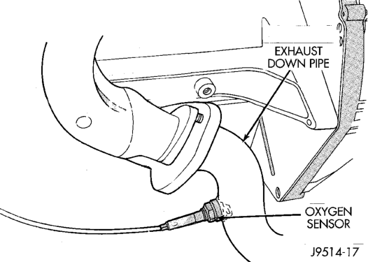
The upstream O2S sensor is located in the exhaust downpipe. The downstream sensor is located near outlet end of catalytic converter. Refer to (Fig. 82) or (Fig. 81).
Engine
REMOVAL
WARNING: THE EXHAUST MANIFOLD, EXHAUST PIPES AND CATALYTIC CONVERTER BECOME VERY HOT DURING ENGINE OPERATION. ALLOW ENGINE TO COOL BEFORE REMOVING OXYGEN SENSOR.
(1) Raise and support vehicle. (2) Downstream Sensor Only: Disconnect O2S wiring connector clip (Fig. 81) at body. Remove clip from O2S electrical connector and discard.
(3) Disconnect O2S pigtail harness wire connector from main connector.
CAUTION: When disconnecting the sensor electrical connector, do not pull directly on wire going into sensor.
(4) Remove O2S sensor. Snap-On oxygen sensor wrench (number YA 8875) may be used for removal and installation.
INSTALLATION
Threads of new oxygen sensors are factory coated with anti-seize compound to aid in removal. DO NOT add any additional anti-seize compound to the threads of a new oxygen sensor.
(1) Install the O2S sensor. Tighten to 30 N·m (22 ft. lbs.) torque.
(2) Connect O2S sensor wire connector to main wiring harness.
(3) Downstream Sensor Only: Install new wiring connector clip into O2S electrical connector. Snap this clip to body. The O2S pigtail harness must be clipped to body to prevent mechanical damage from propshaft.
(4) Lower the vehicle.
AIR CLEANER HOUSING
REMOVAL
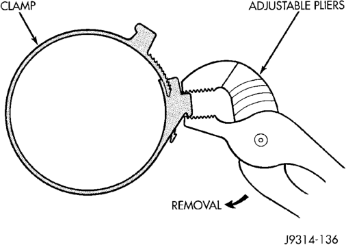
(1) Unlock clean air hose clamp (Fig. 83) at air cleaner cover. To unlock the clamp, attach adjustable pliers to clamp and rotate pliers as shown in (Fig. 84). Remove clean air hose at cover.
(2) Remove crankcase breather/filter hose at air cleaner cover.
(3) From under vehicle, remove three housing nuts (Fig. 83).
(4) Release the air cleaner housing from the ambient air duct and remove housing from vehicle.
INSTALLATION
(1) Position air cleaner housing to body and ambient air duct (Fig. 83).
(2) Install three nuts and tighten to 10 N·m (93 in. lbs.) torque.
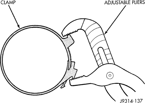
(3) Install crankcase breather/filter hose to cover. (4) Install clamp to cover. Compress the clamp snugly with adjustable pliers as shown in (Fig. 85).
AIR CLEANER ELEMENT (FILTER)
REMOVAL/INSTALLATION
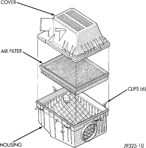
(1) Pry back the six clips retaining the air cleaner cover to the air cleaner housing (Fig. 86).
(2) Lift the cover up and position to the side. (3) Remove air cleaner element. (4) Clean the inside of air cleaner housing before installing new element. (5) Reverse the preceding operation for installation. Be sure the air cleaner cover is properly seated to air cleaner housing.
ENGINE COOLANT TEMPERATURE SENSOR—5.2L/ 5.9L ENGINES
REMOVAL
WARNING: HOT, PRESSURIZED COOLANT CAN CAUSE INJURY BY SCALDING. COOLING SYSTEM MUST BE PARTIALLY DRAINED BEFORE REMOV- ING THE COOLANT TEMPERATURE SENSOR. REFER TO GROUP 7, COOLING.
(1) Partially drain cooling system. Refer to Group 7, Cooling.
(2) Disconnect electrical connector from sensor (Fig. 87).
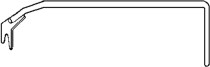
(3) Engines with air conditioning: When removing the connector from sensor, do not pull directly on wiring harness. Fabricate an L-shaped hook tool from a coat hanger (approximately eight inches long). Place the hook part of tool under the connector for removal. The connector is snapped onto the sensor. It is not equipped with a lock type tab.
(4) Remove sensor from intake manifold.
5.9L Engines
INSTALLATION
(1) Install sensor. (2) Tighten to 11 N·m (8 ft. lbs.) torque. (3) Connect electrical connector to sensor. The sensor connector is symmetrical (not indexed). It can be installed to the sensor in either direction. (4) Replace any lost engine coolant. Refer to Group 7, Cooling System.
ENGINE COOLANT TEMPERATURE SENSOR—4.0L ENGINE
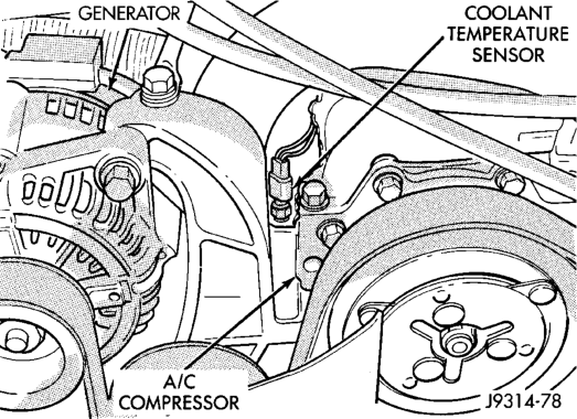
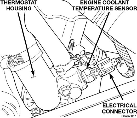
The coolant temperature sensor is installed in the thermostat housing (Fig. 88).
REMOVAL
(1) Partially drain cooling system until the coolant level is below the cylinder head. Observe the WARN- INGS in Group 7, Cooling.
(2) Disconnect the coolant temperature sensor wire connector.
(3) Remove the sensor from the thermostat housing.
INSTALLATION
(1) Apply sealant to sensor threads. (2) Install coolant temperature sensor into the thermostat housing. Tighten to 11 N·m (8 ft. lbs.) torque.
(3) Connect the wire connector.
Engine
(4) Fill the cooling system. Refer to Group 7, Cooling System.
INTAKE MANIFOLD AIR TEMPERATURE SENSOR— 5.2L/5.9L ENGINES
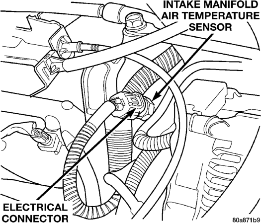
The intake manifold air temperature sensor is located in the front/side of the intake manifold (Fig. 89).
REMOVAL
(1) Disconnect electrical connector at sensor (Fig. 89).
(2) Remove sensor from intake manifold.
Engines—Typical
INSTALLATION
(1) Install sensor to intake manifold. Tighten to 28 N·m (20 ft. lbs.) torque.
(2) Install electrical connector.
INTAKE MANIFOLD AIR TEMPERATURE SENSOR— 4.0L ENGINE
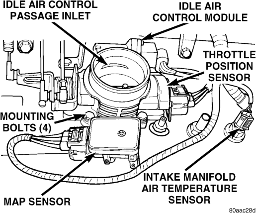
The intake manifold air temperature sensor is installed into the intake manifold plenum near the throttle body (Fig. 90).
REMOVAL
(1) Disconnect the electrical connector from the sensor.
(2) Remove the sensor from the intake manifold.
INSTALLATION
(1) Install the sensor into the intake manifold. Tighten the sensor to 28 N·m (20 ft. lbs.) torque.
(2) Connect the electrical connector to the sensor.
VEHICLE SPEED SENSOR
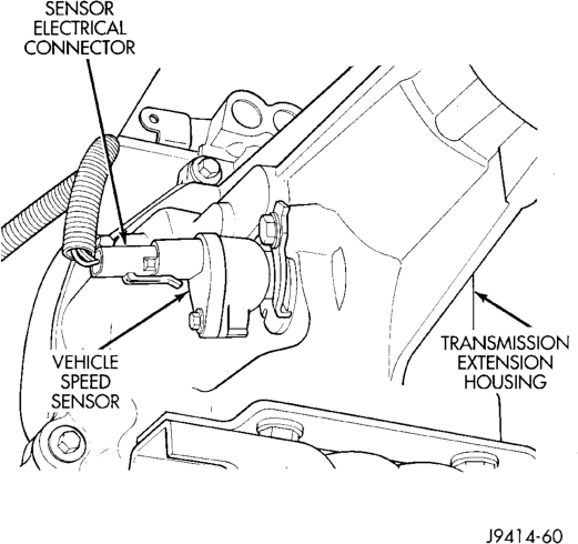
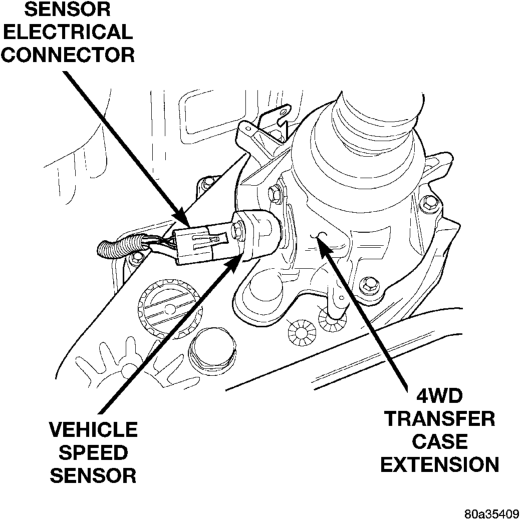
The vehicle speed sensor is located on the speedometer pinion gear adapter (Fig. 91) or (Fig. 92). The pinion gear adapter is located on the extension housing of the transmission (drivers side).
REMOVAL
(1) Raise and support vehicle. (2) Disconnect the electrical connector from the sensor.
(3) Remove the sensor mounting bolt (Fig. 93). (4) Remove the sensor (pull straight out) from the speedometer pinion gear adapter (Fig. 93). Do not remove the gear adapter from the transmission.
Typical
Typical
INSTALLATION
(1) Clean the inside of speedometer pinion gear adapter before installing speed sensor.
(2) Install sensor into speedometer gear adapter and install mounting bolt. Before tightening bolt, verify speed sensor is fully seated (mounted flush) to speedometer pinion gear adapter.
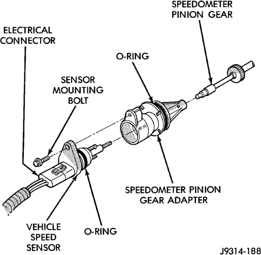
(3) Tighten sensor mounting bolt to 2.2 N·m (20 in. lbs.) torque.
(4) Connect electrical connector to sensor.
SPECIFICATIONS
VECI LABEL
If anything differs between the specifications found on the Vehicle Emission Control Information (VECI) label and the following specifications, use specifications on VECI label. The VECI label is located in the engine compartment.
TORQUE CHART
DESCRIPTION TORQUE Air Cleaner Housing Mount. Nuts . . . . . . . . .10 N·m
(93 in. lbs.) Engine Coolant Temperature Sensor—
All Engines. . . . . . . . . . . . . . . .11 N·m (96 in. lbs.) Fuel Hose Clamps . . . . . . . . . . . . .1 N·m (10 in. lbs.) IAC Motor-To-Throttle
Body Bolts . . . . . . . . . . . . . . . . .7 N·m (60 in. lbs.) Intake Manifold Air Temp. Sensor—
All Engines . . . . . . . . . . . . . . . .28 N·m (20 ft. lbs.) MAP Sensor Mounting Screws—
All Engines . . . . . . . . . . . . . . . .3 N·m (25 in. lbs.) Oxygen Sensor—All Engines . . . .30 N·m (22 ft. lbs.) Powertrain Control Module
Mounting Screws . . . . . . . . . . . . .1 N·m (9 in. lbs.) Throttle Body Mounting Bolts—
5.2L/5.9L Engine . . . . . . . . . .23 N·m (200 in. lbs.) Throttle Body Mounting Bolts—
4.0L Engine . . . . . . . . . . . . . .11 N·m (100 in. lbs.) Throttle Position Sensor Mounting
Screws—All Engines. . . . . . . . . 7 N·m (60 in. lbs.) Vehicle Speed Sensor
Mounting Bolt. . . . . . . . . . . . .2.2 N·m (20 in. lbs.)
SPECIAL TOOLS
FUEL SYSTEM