Exhaust System and Intake Manifold — 1998 Jeep Grand Cherokee ZJ Export Service Manual
Pages 1205–1218 · 13 pages · 1 words repaired
bolt threads, corrosion damage and worn, cracked or broken hangers. Replace all components that are badly corroded or damaged. DO NOT attempt to repair.
When replacement is required, use original equipment parts (or their equivalent). This will assure proper alignment and provide acceptable exhaust noise levels.
CAUTION: Avoid application of rust prevention compounds or undercoating materials to exhaust system floor pan heat shields. Light over spray near the edges is permitted. Application of coating will result in excessive floor pan temperatures and objectionable fumes.
CATALYTIC CONVERTER
CAUTION: DO NOT remove spark plug wires from plugs or by any other means short out cylinders. Failure of the catalytic converter can occur due to a temperature increase caused by unburned fuel passing through the converter.
The stainless steel catalytic converter body is designed to last the life of the vehicle. Excessive heat can result in bulging or other distortion, but excessive heat will not be the fault of the converter. If unburned fuel enters the converter, overheating may occur. If a converter is heat-damaged, correct the cause of the damage at the same time the converter is replaced. Also, inspect all other components of the exhaust system for heat damage.
Unleaded gasoline must be used to avoid contaminating the catalyst core.
HEAT SHIELDS
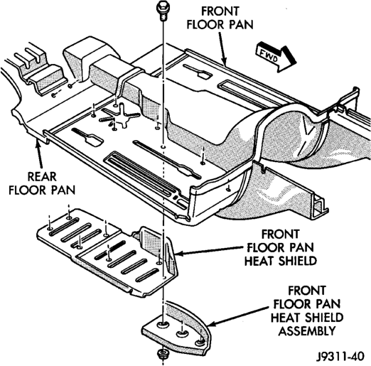
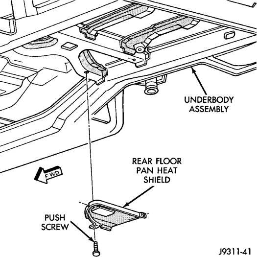
Heat shields are needed to protect both the vehicle and the environment from the high temperatures developed by the catalytic converter (Fig. 3) (Fig. 4). The catalytic converter releases additional heat into the exhaust system. Under severe operating conditions, the temperature increases in the area of the converter. Such conditions can exist when the engine misfires or otherwise does not operate at peak efficiency.
DIAGNOSIS AND TESTING
EXHAUST SYSTEM DIAGNOSIS
CONDITION POSSIBLE CAUSE CORRECTION
EXCESSIVE EXHAUST NOISE
LEAKING EXHAUST GASES
REMOVAL AND INSTALLATION
EXHAUST PIPE
REMOVAL
WARNING: IF TORCHES ARE USED WHEN WORK- ING ON THE EXHAUST SYSTEM, DO NOT ALLOW THE FLAME NEAR THE FUEL LINES.
CAUTION: When servicing exhaust system components, disconnect the oxygen sensor connector‘(s). Allowing the exhaust system to hang by the oxygen sensor harness will damage the sensor and/or wiring.
(1) Raise and support the vehicle. (2) Saturate the bolts and nuts with heat valve lubricant. Allow 5 minutes for penetration.
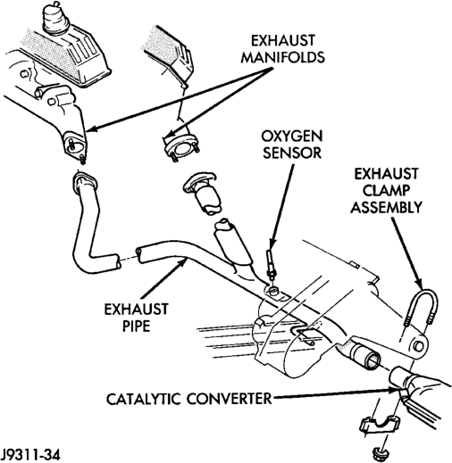
(3) Remove the oxygen sensor from the exhaust pipe (Fig. 5) (Fig. 6).
(4) Disconnect the exhaust pipe from the engine exhaust manifold. On 4.0L engines, discard the exhaust manifold seal (Fig. 5).
(5) Remove the exhaust clamp from the exhaust pipe and catalytic converter connection (Fig. 5) (Fig. 6). Disconnect the exhaust pipe from the catalytic converter. If needed:
(a) Heat the exhaust pipe and catalytic converter connection with an torch until the metal becomes cherry red.
1. Leaks at pipe joints. 1. Tighten clamps at leaking joints.
2. Burned or blown out muffler. 2. Replace muffler assembly. Check exhaust system. 3. Burned or rusted-out exhaust pipe. 3. Replace exhaust pipe. 4. Exhaust pipe leaking at manifold flange.
4. Tighten connection attaching nuts.
5. Exhaust manifold cracked or broken. 5. Replace exhaust manifold. 6. Leak between exhaust manifold and cylinder head.
6. Tighten exhaust manifold to cylinder head stud nuts or bolts. 7. Restriction in muffler or tailpipe. 7. Remove restriction, if possible. Replace muffler or tailpipe, as necessary. 8. Exhaust system contacting body or chassis.
8. Re-align exhaust system to clear surrounding components.
1. Leaks at pipe joints. 1. Tighten/replace clamps at leaking joints. 2. Damaged or improperly installed gaskets.
2. Replace gaskets as necessary
(b) While the metal is still cherry red, twist the exhaust pipe back and forth to separate it from the catalytic converter. (6) Disconnect the exhaust pipe hanger from the rear mount bracket insulator.
(7) Remove the exhaust pipe.
INSTALLATION
(1) Position the exhaust pipe onto the catalytic converter.
(2) Connect the exhaust pipe hanger to the rear mount bracket insulator.
(3) On 4.0L engines, install a new seal between the exhaust pipe and the engine exhaust manifold (Fig. 5). Connect the exhaust pipe to the engine exhaust manifold. Tighten the nuts to 31 N·m (23 ft. lbs.) torque.
(4) Position the exhaust clamp over the exhaust pipe/catalytic converter connection (Fig. 5) (Fig. 6). Tighten the nuts to 48 N·m (35 ft. lbs.) torque.
(5) Coat the oxygen sensor with anti-seize compound. Install the sensor and tighten the nut to 30 N·m (22 ft. lbs.) torque.
(6) Lower the vehicle. (7) Start the engine and inspect for exhaust leaks and exhaust system contact with the body panels. Adjust the alignment, if needed.
(8) After initial start-up, check the exhaust manifold to pipe nuts for proper torque.
CATALYTIC CONVERTER
REMOVAL
WARNING: IF TORCHES ARE USED WHEN WORK- ING ON THE EXHAUST SYSTEM, DO NOT ALLOW THE FLAME NEAR THE FUEL LINES.
(1) Raise and support the vehicle. (2) Saturate the bolts and nuts with heat valve lubricant. Allow 5 minutes for penetration.
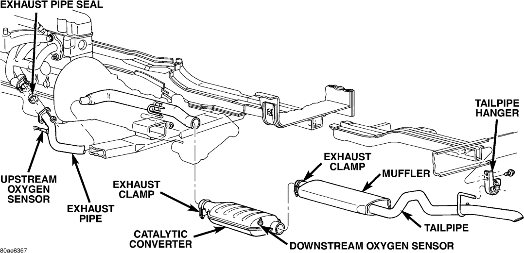
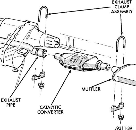
(3) Remove exhaust clamp from the catalytic converter and exhaust pipe connection (Fig. 7).
(4) Remove exhaust clamp from the catalytic converter and muffler connection (Fig. 7).
(5) Disconnect oxygen sensor wiring.
Connection
(6) Heat the exhaust pipe, catalytic converter and muffler connections with an torch until the metal becomes cherry red.
(7) While the metal is still cherry red, twist the catalytic converter back and forth to separate it from the exhaust pipe and the muffler.
INSTALLATION
(1) Position the exhaust clamp over the exhaust pipe/catalytic converter connection (Fig. 7). Tighten the nuts to 61 N·m (45 ft. lbs.) torque.
(2) Install the muffler onto the catalytic converter until the alignment tab is inserted into the alignment slot.
(3) Install the exhaust clamp at the muffler and catalytic converter connection (Fig. 7). Tighten the clamp nuts to 61 N·m (45 ft. lbs.) torque.
(4) Connect oxygen sensor wiring. (5) Lower the vehicle. (6) Start the engine and inspect for exhaust leaks and exhaust system contact with the body panels. Adjust the alignment, if needed.
MUFFLER AND TAILPIPE
REMOVAL
All original equipment exhaust systems are manufactured with the tailpipe welded to the muffler. Service replacement mufflers and tailpipes are either clamped together or welded together.
WARNING: IF TORCHES ARE USED WHEN WORK- ING ON THE EXHAUST SYSTEM, DO NOT ALLOW THE FLAME NEAR THE FUEL LINES.
(1) Raise and support the vehicle. (2) Saturate the bolts and nuts with heat valve lubricant. Allow 5 minutes for penetration.
(3) Remove the exhaust clamp from the catalytic converter and muffler connection (Fig. 7).
(4)
with an torch until the metal becomes cherry red
(5) While the metal is still cherry red, remove the tailpipe/muffler assembly from the catalytic converter.
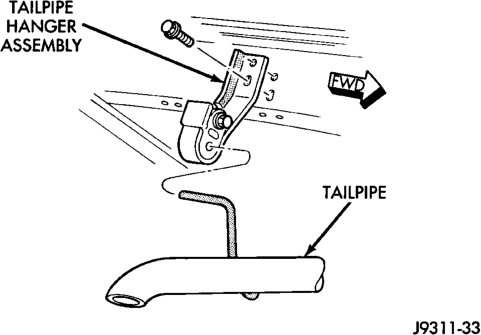
(6) Remove the tailpipe from the tailpipe hanger (Fig. 8).
(7) Remove the tailpipe/muffler assembly.
INSTALLATION
(1) If the tailpipe hanger assembly was removed, install the hanger to the frame. Tighten the bolts to 22 N·m (192 in. lbs.) torque.
(2) Position the tailpipe and muffler onto the tailpipe hanger (Fig. 8).
(3) Install the muffler onto the catalytic converter. Make sure that the tailpipe has sufficient clearance from the floor pan. Install exhaust clamp and tighten the nuts to 61 N·m (45 ft. lbs.) torque.
(4) Lower the vehicle.
(5) Start the engine and inspect for exhaust leaks and exhaust system contact with the body panels. Adjust the alignment, if needed.
INTAKE AND EXHAUST MANIFOLD—4.0L ENGINE
REMOVAL
NOTE: THE ENGINE INTAKE AND EXHAUST MANI- FOLD MUST BE REMOVED AND INSTALLED TOGETHER. THE MANIFOLDS USE A COMMON GASKET AT THE CYLINDER HEAD.
(1) Disconnect the battery negative cable. (2) Remove air cleaner inlet hose from throttle body assembly.
(3) Remove the air cleaner assembly. (4) Remove the throttle cable, vehicle speed control cable (if equipped) and the transmission line pressure cable.
(5) Disconnect the following electrical connections and secure their harness out of the way:
• Throttle Position Sensor • Idle Air Control Motor • Coolant Temperature Sensor (at thermostat housing)
• Intake Air Temperature Sensor • Oxygen Sensor • Crank Position Sensor • Six (6) Fuel Injector Connectors (6) Disconnect the Map Sensor, HVAC, and Brake Booster vacuum supply hoses at the intake manifold.
(7)
Perform the fuel pressure release procedure.
(Refer to Group 14, Fuel Systems for correct procedure)
(8) Disconnect and remove the fuel system supply line from the fuel rail assembly. (Refer to Group 14, Quick Connect Fittings for correct procedures)
(9) Loosen the accessory drive belt (refer to Group 7, Cooling System). Loosen the tensioner.
(10) Remove the power steering pump and bracket from the intake manifold and set aside.
(11) Raise the vehicle. (12) Disconnect the exhaust pipe from the engine exhaust manifold. Discard the seal.
(13) Lower the vehicle. (14) Remove the intake manifold and engine exhaust manifold.
INSTALLATION
If the manifold is being replaced, ensure all the fitting, etc. are transferred to the replacement manifold.
(1) Install a new engine exhaust/intake manifold gasket over the alignment dowels on the cylinder head.
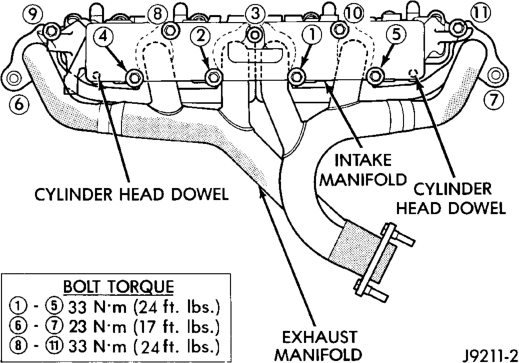
(2) Position the engine exhaust manifold to the cylinder head. Install fastener Number 3 and finger tighten at this time (Fig. 9).
(3) Install intake manifold on the cylinder head dowels.
(4) Install washer and fastener Numbers 1, 2, 4, 5, 8, 9, 10 and 11 (Fig. 9).
(5) Install washer and fastener Numbers 6 and 7 (Fig. 9).
(6) Tighten the fasteners in sequence and to the specified torque (Fig. 9).
• Fastener Numbers 1 through 5—Tighten to 33 N·m (24 ft. lbs.) torque.
• Fastener Numbers 6 and 7—Tighten to 31 N·m (23 ft. lbs.) torque.
• Fastener Numbers 8 through 11—Tighten to 33 N·m (24 ft. lbs.) torque.
(7) Install the power steering pump and bracket to the intake manifold. Tighten the belt to specification. (Refer to Group 7, Cooling System for the correct procedures)
(8) Install the fuel system supply line to the fuel rail assembly. Before connecting the fuel supply line to the fuel rail inspect the O-rings and replace if necessary. Refer to Group 14, Fuel System for the correct procedure.
(9) Connect all electrical connections on the intake manifold.
(10) Connect the vacuum hoses previously removed.
(11) Install throttle cable, vehicle speed control cable (if equipped).
(12) Install the transmission line pressure cable (if equipped). Refer to Group 21, Transmission for the adjustment procedures.
(13) Install air cleaner assembly. (14) Connect air inlet hose to the throttle body assembly.
(15) Raise the vehicle. (16) Using a new exhaust manifold seal, connect the exhaust pipe to the engine exhaust manifold. Tighten the bolts to 31 N·m (23 ft. lbs.)
(17) Lower the vehicle. (18) Connect the battery negative cable. (19) Start the engine and check for leaks.
INTAKE MANIFOLD—5.2/5.9L ENGINE
REMOVAL
The aluminum intake manifold is a single plane design with equal length runners. The manifold is sealed by flange side gaskets with front and rear cross-over gaskets. The intake manifold has internal EGR.
(1) Disconnect the battery negative cable. (2) Drain the cooling system (refer to Group 7, Cooling System for the proper procedures).
(3) Remove the generator (refer to Group 8B Battery/Starting/Charging Systems).
(4) Remove the air cleaner. (5) Remove the fuel supply line and fuel rail (refer to Group 14, Fuel System).
(6) Disconnect the accelerator linkage and, if so equipped, the speed control and transmission kickdown cables.
(7) Remove the distributor cap and wires. (8) Disconnect the coil wires. (9) Disconnect the heat indicator sending unit wire.
(10) Disconnect the heater hoses and bypass hose. (11) Remove the closed crankcase ventilation and evaporation control systems.
(12) Remove the A/C compressor bolts and set the compressor on the fan shroud.
(13) Remove the support bracket from the intake manifold and the mounting bracket.
(14) Remove intake manifold bolts. (15) Lift the intake manifold and throttle body out of the engine compartment as an assembly.
(16) Remove and discard the flange side gaskets and the front and rear cross-over gaskets.
(17) Remove the throttle body bolts and lift the throttle body off the intake manifold. Discard the throttle body gasket.
(18) Remove the plenum pan as follows:
(a) Turn the intake manifold upside down. Support the manifold.
(b) Remove the bolts and lift the pan off the manifold. Discard the gasket.
INSTALLATION
(1) Install the plenum pan, if removed, as follows:
(a) Turn the intake manifold upside down. Support the manifold.
(b) Place a new plenum pan gasket onto the seal rail of the intake manifold. Position the pan over the gasket. Align all the gasket and pan holes with the intake manifold.
(c) Hand start all bolts. (d) Tighten the bolts, in sequence (Fig. 10), as follows:
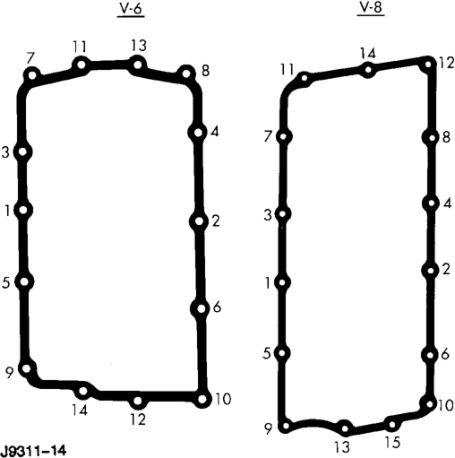
• Step 1—Tighten bolts to 2.7 N·m (24 in. lbs.) torque.
• Step 2—Tighten bolts to 5.4 N·m (48 in. lbs.) torque.
• Step 3—Tighten bolts to 9.5 N·m (84 in. lbs.) torque.
• Step 4—Check that all bolts are tighten to 9.5 N·m (84 in. lbs.) torque.
(2) Using a new gasket, install the throttle body onto the intake manifold. Tighten the bolts to 23 N·m (200 in. lbs.) torque.
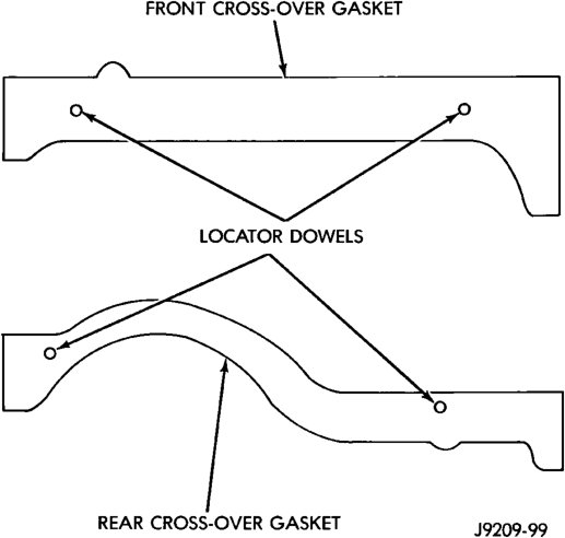
(3) Place the 4 plastic locator dowels into the holes in the block (Fig. 11).
(4) Apply Mopart Silicone Rubber Adhesive Sealant, or equivalent, to the four corner joints. An excessive amount of sealant is not required to ensure a leak proof seal. However, an excessive amount of sealant may reduce the effectiveness of the flange gasket. The sealant should be slightly higher than the cross-over gaskets, approximately 5 mm (0.2 in).
(5) Install the front and rear cross-over gaskets onto the dowels (Fig. 11).
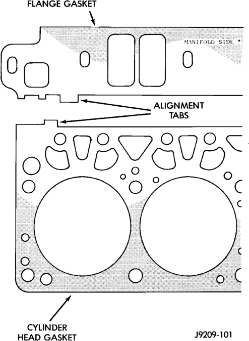
(6) Install the flange gaskets. Ensure that the vertical port alignment tab is resting on the deck face of the block. Also the horizontal alignment tabs must be in position with the mating cylinder head gasket tabs (Fig. 12). The words MANIFOLD SIDE should be visible on the center of each flange gasket. (7) Carefully lower intake manifold into position on the cylinder block and cylinder heads. Use the alignment dowels in the cross-over gaskets to position the intake manifold. After intake manifold is in place, inspect to make sure seals are in place.
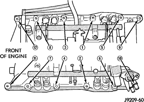
(8) The following torque sequence duplicates the expected results of the automated assembly system (Fig. 13).
• Step 1—Tighten bolts 1 through 4, in sequence, to 8 N·m (72 in. lbs.) torque. Tighten in alternating steps 1.4 N·m (12 in. lbs.) torque at a time.
• Step 2—Tighten bolts 5 through 12, in sequence, to 8 N·m (72 in. lbs.) torque.
• Step 3—Check that all bolts are tighten to 8 N·m (72 in. lbs.) torque.
• Step 4—Tighten all bolts, in sequence, to 16 N·m (12 ft. lbs.) torque.
• Step 5—Check that all bolts are tighten to 16 N·m (12 ft. lbs.) torque.
(9) Install closed crankcase ventilation and evaporation control systems.
(10) Install the coil wires. (11) Connect the heat indicator sending unit wire. (12) Connect the heater hoses and bypass hose. (13) Install distributor cap and wires. (14) Hook up the return spring. (15) Connect the accelerator linkage and, if so equipped, the speed control and transmission kickdown cables.
(16) Install the fuel lines and fuel rail (refer to Group 14, Fuel System).
(17) Install the support bracket to the intake manifold and the mounting bracket. (18) Install the generator and drive belt. Tighten generator mounting bolt to 41 N·m (30 ft. lbs.) torque. Tighten the adjusting strap bolt to 23 N·m (200 in. lbs.) torque. Refer to Group 7, Cooling System for the proper adjusting of belt tension.
(19) Install the A/C compressor on the mounting bracket (refer to Group 24, Heating and Air Conditioning).
(20) Install the air cleaner. (21) Fill cooling system (refer to Group 7, Cooling System for the proper procedure).
(22) Connect the battery negative cable.
EXHAUST MANIFOLD—5.2/5.9L ENGINE
REMOVAL
Exhaust manifolds are LOG type with balanced flow.
(1) Disconnect the negative cable from the battery. (2) Remove the exhaust manifold heat shields (Fig. 14).
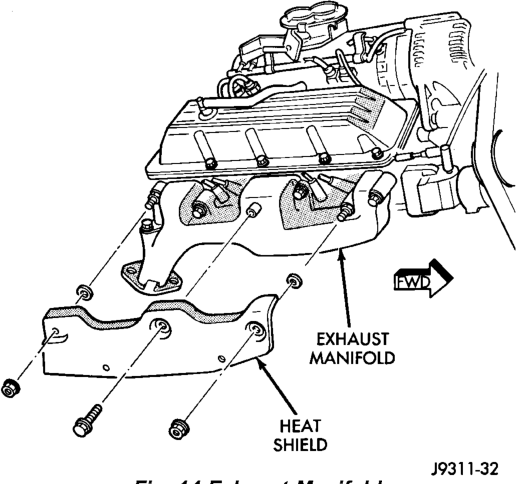
Heat Shields (Left Shield Shown)
(3) Remove the EGR tube (refer to Group 25, Emission Control Systems).
(4) Raise the vehicle. (5) Remove the bolts and nuts attaching the exhaust pipe to the exhaust manifold.
(6) Lower the vehicle. (7) Remove bolts, nuts and washers attaching manifold to cylinder head.
(8) Remove manifold from the cylinder head.
INSTALLATION
CAUTION: If the studs came out with the nuts when removing the exhaust manifold, install new studs.
(1) Position the exhaust manifolds on the two studs located on the cylinder head. Install conical washers and nuts on these studs (Fig. 15).
(2) Install new bolt and washer assemblies in the remaining holes (Fig. 15). Start at the center arm and work outward. Tighten the bolts and nuts to 27 N·m (20 ft. lbs.) torque.
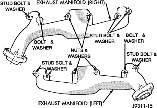
(3) Raise the vehicle. (4) Assemble the exhaust pipe to the exhaust manifold and secure with bolts, nuts and washers. Tighten these nuts to 31 N·m (23 ft. lbs.) torque.
(5) Lower the vehicle. (6) Install the EGR tube (refer to Group 25, Emission Control Systems).
CAUTION: The exhaust manifold heat shields MUST be installed to protect the underhood components.
(7) Install the exhaust manifold heat shields. Tighten the nuts to 27 N·m (20 ft. lbs.) torque.
(8) Connect the negative cable to the battery.
CLEANING AND INSPECTION
INTAKE AND EXHAUST MANIFOLD—4.0L ENGINE
Clean the mating surfaces of the cylinder head and the manifold if the original manifold is to be installed.
INTAKE MANIFOLD— 5.2/5.9L ENGINE
CLEANING
Clean manifold in solvent and blow dry with compressed air.
Clean cylinder block front and rear gasket surfaces using a suitable solvent.
The plenum pan rail must be clean and dry (free of all foreign material).
INSPECTION
Inspect manifold for cracks. Inspect mating surfaces of manifold for flatness with a straightedge.
EXHAUST MANIFOLD—5.2/5.9L ENGINE
CLEANING
Clean mating surfaces on cylinder head and manifold, wash with solvent and blow dry with compressed air. Inspect manifold for cracks.
INSPECTION
Inspect mating surfaces of manifold for flatness with a straight edge. Seal surfaces must be flat within 0.1 mm (0.004 inch) overall.
SPECIFICATIONS
TORQUE
DESCRIPTION TORQUE Catalytic Converter to Exhaust Pipe
Exhaust Clamp . . . . . . . . . . . . .48 N·m (35 ft. lbs.) Exhaust Pipe to Manifold
Nuts . . . . . . . . . . . . . . . . . . . . .31 N·m (23 ft. lbs.) Exhaust Manifold Heat Shield–(5.2L/5.9L)
Nuts . . . . . . . . . . . . . . . . . . . . .27 N·m (20 ft. lbs.) Exhaust Manifold–(5.2L/5.9L)
Nuts/Bolts . . . . . . . . . . . . . . . . .27 N·m (20 ft. lbs.) Floor Pan Heat Shield
Bolts/Nuts. . . . . . . . . . . . . . . . . .5 N·m (45 in. lbs.) Generator Mounting
Bolts . . . . . . . . . . . . . . . . . . . . .41 N·m (30 ft. lbs.) Intake/Exhaust Manifold—(4.0L) Intake/Exhaust Manifold
Nuts/Bolts #1,2,4,5,8–11. . . . . . .33 N·m (24 ft.lbs.) Exhaust Manifold Bolt #3 . . . . . . .33 N·m (24 ft. lbs.) Exhaust Manifold Nuts #6&7 . . . .31 N·m (23 ft. lbs.) Intake Manifold–(5.2L/5.9L)
Bolts . . . . . . . . .Refer to Procedure in This Section Muffler to Catalytic Converter
Exhaust Clamp . . . . . . . . . . . . .48 N·m (35 ft. lbs.) Oxygen Sensor
Sensor . . . . . . . . . . . . . . . . . . . .30 N·m (22 ft. lbs.) Plenum Pan–(5.2L/5.9L)
Bolts . . . . . . . .Refer to Procedure in This Section Rear Tailpipe Hanger
Bolts . . . . . . . . . . . . . . . . . . . .22 N·m (192 in. lbs.)
REMOVAL AND INSTALLATION
EXHAUST PIPE
WARNING: IF TORCHES ARE USED WHEN WORK- ING ON THE EXHAUST SYSTEM, DO NOT ALLOW THE FLAME NEAR THE FUEL LINES.
REMOVAL
(1) Raise and support the vehicle. (2) Saturate the bolts and nuts at turbo down pipe to exhaust pipe with heat valve lubricant. Allow 5 minutes for penetration.
(3) Disconnect bolts from exhaust pipe to turbo down pipe (Fig. 2).
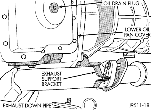
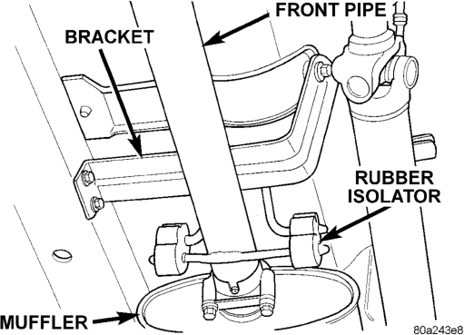
(4) Remove the clamp nuts at muffler (Fig. 3). To remove the exhaust pipe from the muffler, apply heat until the metal becomes cherry red. Disconnect the exhaust pipe from the muffler. Remove the exhaust pipe.
INSTALLATION
(1) Assemble exhaust pipe to muffler, loosely to permit proper alignment of all parts.
(2) Connect the exhaust pipe to the turbo down pipe manifold. Tighten the bolts to 22.5 N·m torque.
(3) Use a new clamp and tighten the nuts to 43 N·m torque.
(4) Lower the vehicle. (5) Start the engine and inspect for exhaust leaks and exhaust system contact with the body panels. Adjust the alignment, if needed.
MUFFLER AND EXHAUST TAILPIPE
All original equipment exhaust systems are manufactured with the exhaust tailpipe welded to the muffler. Service replacement mufflers and exhaust tailpipes are either clamped together or welded together.
WARNING: IF TORCHES ARE USED WHEN WORK- ING ON THE EXHAUST SYSTEM, DO NOT ALLOW THE FLAME NEAR THE FUEL LINES.
REMOVAL
(1) Raise and support the vehicle. (2) Remove the front muffler clamp from the exhaust pipe and muffler connection.
(3) Remove the rear exhaust tailpipe hanger clamp and remove the exhaust tailpipe from the front exhaust tailpipe hanger.
(4) Remove the exhaust tailpipe assembly from the muffler.
INSTALLATION
(1) Install the muffler onto the exhaust pipe. Install the clamp and tighten the nuts finger tight.
(2) Install the exhaust tailpipe into the rear of the muffler.
(3) Install the exhaust tailpipe/muffler assembly on the rear exhaust tailpipe hanger. Make sure that the exhaust tailpipe has sufficient clearance from the floor pan.
(4) Install the remaining clamps and the front exhaust tailpipe hanger.
(5) Tighten the nuts on the muffler-to-exhaust pipe clamp to 43 N·m torque.
(6) Tighten the nuts on the muffler-to-exhaust pipe clamp to 43 N·m torque.
(7) Lower the vehicle. (8) Start the engine and inspect for exhaust leaks and exhaust system contact with the body panels. Adjust the alignment, if needed.
ENGINE EXHAUST MANIFOLD AND TURBOCHARGER
REMOVAL
(1) Disconnect the battery negative cable. (2) Remove air cleaner hoses from turbocharger. (3) Remove air cleaner assembly. (4) Remove charge air cooler hoses from turbocharger and intake manifold.
(5) Remove all components attached to the intake manifold.
(6) Remove the EGR tube and EGR valve. (7) Remove exhaust manifold heat shield. (8) Remove turbocharger oil feed line. (9) Remove exhaust down pipe from turbo. (10) Raise the vehicle. (11) Remove oil drain tube from turbocharger. (12) Lower the vehicle. (13) Remove turbocharger and exhaust manifold as an assembly.
CLEANING
Clean the exhaust manifold and cylinder head mating surfaces.
INSTALLATION
(1) Install turbocharger to exhaust manifold tighten nuts to 27 N·m.
(2) Install assembly to engine, tighten nuts to 30 N·m.
(3) Install oil feed line to turbocharger, tighten nut to 26 N·m.
(4) Install exhaust down pipe to turbocharger, tighten bolts to 27 N·m.
(5) Install exhaust heat shield, tighten bolts to 11 N·m.
(6) Loose install EGR tube and EGR valve to intake manifold. (7) Install EGR valve, tighten bolts to 26 N·m. (8) Tighten EGR tube nut to 26 N·m. (9) Tighten EGR tube flange bolts to 26 N·m. (10) Connect all components to intake manifold. (11) Connect charge air cooler hoses to turbocharger and intake manifold.
(12) Install air cleaner assembly. (13) Connect air cleaner hose to turbocharger. (14) Raise the vehicle. (15) Install turbocharger drain line. (16) Lower the vehicle. (17) Connect the battery negative cable. (18) Start the engine and check for leaks.
INTAKE MANIFOLD
REMOVAL
(1) Remove exhaust manifold and turbocharger assembly.
(2) Remove water manifold. (3) Remove intake manifold.
CLEANING
Clean the intake manifold and cylinder head mating surfaces. DO NOT allow foreign material to enter either the intake manifold or the ports in the cylinder head.
INSTALLATION
(1) Install the new intake manifold gasket. (2) Position the intake manifold in place and finger tighten the mounting nuts.
(3) Tighten the fasteners in sequence and to the specified torque 30 N·m.
(4) Position the water manifold in place and finger tighten the mounting nuts.
(5) Tighten the fasteners to the specified torque 12 N·m.
(6) Install exhaust manifold and turbocharger assembly.
(7) Install charge air cooler hose to intake manifold.
(8) Connect the battery negative cable. (9) Start engine and check for leaks.
SPECIFICATIONS
TORQUE SPECIFICATIONS
Description Torque EGR Attaching Nuts . . . . . . . . . . . . . . . . . . . . . . 19 N·m EGR Tube Nut . . . . . . . . . . . . . . . . . . . . . . . . . . . 34 N·m EGR Tube Flange Bolts . . . . . . . . . . . . . . . . . . . . 26 N·m Exhaust Manifold Nuts . . . . . . . . . . . . . . . . . . . . . . . . . . . . . . . 30 N·m Exhaust Manifold Heat Shield Nuts . . . . . . . . . . . . . . . . . . . . . 11 N·m Exhaust Pipe Support Clamp Bolts . . . . . . . . . . . . . . . . . 22.5 N·m Exhaust Pipe Support Clamp Screw . . . . . . . . . . . . . . . . 22.5 N·m Intake Manifold Nuts . . . . . . . . . . . . . . . . . . . . . . . . . . . . . . . 30 N·m Muffler-to-Exhaust Pipe Clamp Nuts . . . . . . . . . . . . . . . . . . . . . . . . . 43 N·m Tail Pipe Clamp Hanger bolt . . . . . . . . . . . . . . . . . . . . . . . . 22.5 N·m Turbocharger-to-Exhaust manifold Nuts . . . . . . . . . . . . . . . . . . . . . . . . . . . . . . . 27 N·m Turbocharger Oil Feed Line . . . . . . . . . . . . . . . . . . . . . . 27.4 N·m
Description Torque Turbocharger Down Pipe-to-Exhaust Pipe Bolts/Nuts . . . . . . . . . . . . . . . . . . . . . . . . . 22.5 N·m Turbocharger Down Pipe-to-Turbocharger Bolts . . . . . . . . . . . . . . . . . . . . . . . . . . . . . . . 27 N·m