Engine — part 2 of 3 — 1998 Jeep Grand Cherokee ZJ Export Service Manual
← Contents 1 2 3
Pages 1097–1156 · 60 pages · 16 words repaired
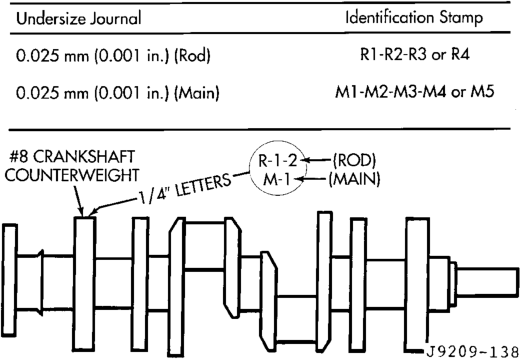
nal is 0.025 mm (0.001 in) undersize. M4 indicates that the No.4 main journal is 0.025 mm (0.001 in) undersize. R3 M2 indicates that the No.3 rod journal and the No.2 main journal are 0.025 mm (0.001 in) undersize.
When a crankshaft is replaced, all main and connecting rod bearings should be replaced with new bearings. Therefore, selective fitting of the bearings is not required when a crankshaft and bearings are replaced.
REMOVAL AND INSTALLATION
ENGINE MOUNTS—FRONT
REMOVAL
(1) Disconnect the negative cable from the battery. (2) Position fan to assure clearance for radiator top tank and hose.
CAUTION: DO NOT lift the engine by the intake manifold.
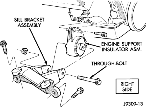
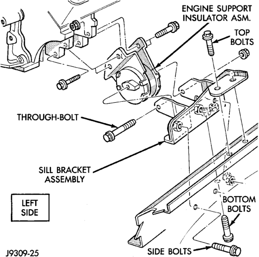
(3) Install engine lifting fixture. (4) Raise vehicle on hoist. (5) Remove the engine support insulator thru-bolts and nuts (Fig. 14) (Fig. 15).
(6) Raise engine SLIGHTLY. Remove the engine support insulator bolts. Remove the engine support insulator assembly.
(7) If required, remove the sill bracket assembly.
INSTALLATION
(1) If the sill bracket assembly was removed, install the bracket to the sill assembly.
(a) RIGHT SIDE—Install the sill bracket assembly onto the sill assembly (Fig. 14). Install and tighten the bolts to 65 N·m (48 ft. lbs.) torque.
(b) LEFT SIDE—Install the sill bracket assembly onto the sill assembly (Fig. 15). Install and tighten the 2 top bolts to 65 N·m (48 ft. lbs.) torque. Install and tighten the 2 side bolts to 95 N·m (70 ft. lbs.) torque. Install and tighten the 2 bottom bolts to 121 N·m (89 ft. lbs.) torque. (2) With the engine raised SLIGHTLY, position engine support insulator assembly onto the engine block (Fig. 14) (Fig. 15). Install bolts and tighten to 88 N·m (65 ft. lbs.) torque.
(3) Lower engine with lifting fixture while aligning engine support insulator assembly into sill bracket assembly.
(4) Install the thru-bolt and nut. Tighten the RIGHT SIDE nut to 81 N·m (60 ft. lbs.) torque. Tighten the LEFT SIDE nut to 81 N·m (60 ft. lbs.) torque.
(5) Lower the vehicle. (6) Remove lifting fixture. (7) Connect the negative cable to the battery.
ENGINE MOUNT—REAR
REMOVAL
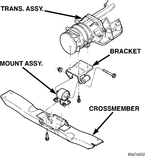
(1) Disconnect the negative cable from the battery. (2) Raise the vehicle on a hoist. (3) Support the transmission with a jack. (4) Remove stud nuts attaching engine mount to crossmember (Fig. 16). Remove mount.
(5) Raise the transmission and engine SLIGHTLY. (6) Remove engine mount bracket thru-bolt (Fig. 16).
(7) Remove the engine mount assembly from the adaptor (Fig. 16).
(8) If required, remove the transmission support bracket adaptor.
INSTALLATION
(1) Position the rear mount bracket onto the exhaust hanger (if previously removed). Position the rear mount bracket assembly onto the transmission and install the bolts. Tighten the bolts to 46 N·m (34 ft. lbs.).
(2) Position mount into mount bracket and install thru-bolt and nut. DO NOT tighten the bolt at this time.
(3) Lower the transmission until the mount fastening studs are in position in the crossmember. (4) Remove transmission jack. (5) Install the mount fastening nuts and tighten the nuts to 54 N·m (40 ft. lbs.) torque.
(6) Tighten the thru-bolt nut to 65 N·m (48 ft. lbs.) torque.
(7) Lower the vehicle.
(8) Connect the negative cable to the battery.
ENGINE ASSEMBLY
REMOVAL
(1) Scribe hood hinge outlines on hood and remove the hood.
(2) Remove the battery. (3) Drain cooling system. (4) Remove the air cleaner and tube. (5) Set fan shroud aside. (6) Remove radiator and heater hoses. Remove the radiator (refer to Group 7, Cooling System).
(7) Remove the vacuum lines. (8) Remove the distributor cap and wiring. (9) Disconnect the accelerator linkage. (10) Perform the Fuel System Pressure Release procedure (refer to Group 14, Fuel System).
(11) Remove throttle body. (12) Remove the starter wires. (13) Remove the oil pressure wire. (14) Discharge the air conditioning system, if equipped (refer to Group 24, Heating and Air Conditioning for service procedures).
(15) Remove air conditioning hoses. (16) Disconnect the power steering hoses, if equipped.
(17) Remove starter motor (refer to Group 8B, Battery/Starter Service).
(18) Remove the generator (refer to Group 8C, Generator Service).
(19) Raise and support the vehicle on a hoist. (20) Disconnect exhaust pipe at manifold.
(21) Support automatic transmission with a transmission stand. This will assure that the torque converter will remain in proper position in the transmission housing.
(22) Remove bell housing bolts and inspection plate. Attach C-clamp on front bottom of transmission torque converter housing to prevent torque converter from coming out.
(23) Remove torque converter drive plate bolts from torque converter drive plate. Mark converter and drive plate to aid in assembly.
(24) Disconnect the engine from the torque converter drive plate.
CAUTION: DO NOT lift the engine by the intake manifold.
(25) Install an engine lifting fixture. (26) Remove the engine front mount thru-bolts. (27) Lower the vehicle. (28) Remove engine from engine compartment. (29) Install on engine repair stand.
INSTALLATION
(1) Remove engine from the repair stand and position in the engine compartment.
(2) Install engine support fixture. (3) Raise and support the vehicle on a hoist. (4) Position the torque converter and drive plate. Install torque converter drive plate bolts. Tighten the bolts to 31 N·m (270 in. lbs.) torque.
(5) Install the engine front mount thru-bolts. (6) Install bell housing bolts. Tighten the bolts to 41 N·m (30 ft. lbs.) torque.
(7) Remove C-clamp and install inspection plate. (8) Remove stand from transmission. (9) Install exhaust pipe to manifold. (10) Lower the vehicle. (11) Remove engine lifting fixture. (12) Install the generator (refer to Group 8C, Generator Service).
(13) Install starter motor (refer to Group 8B, Battery/Starter Service).
(14) Install power steering hoses, if equipped. (15) Install air conditioning hoses. (16) Charge the air conditioner, if equipped (refer to Group 24, Heater and Air Conditioning for service procedures).
(17) Using a new gasket, install throttle body. Tighten the throttle body bolts to 23 N·m (200 in. lbs.) torque.
(18) Connect the accelerator linkage. (19) Connect the starter wires. (20) Connect the oil pressure wire. (21) Install the distributor cap and wiring. (22) Install vacuum lines.
(23) Install radiator, radiator hoses and heater hoses (refer to Group 7, Cooling System).
(24) Install fan shroud in position. (25) Install the battery (26) Fill cooling system (refer to Group 7, Cooling System for the proper procedure).
(27) Install the air cleaner. (28) Warm engine and adjust. (29) Install hood and line up. (30) Road test vehicle.
CYLINDER HEAD COVER
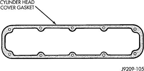
A steel backed silicon gasket is used with the cylinder head cover (Fig. 17). This gasket can be used again.
REMOVAL
(1) Disconnect the negative cable from the battery. (2) Disconnect closed ventilation system and evaporation control system from cylinder head cover.
(3) On the left cover, remove the coolant tube bracket.
(4) Remove the ignition wires from the holders. (5) Remove cylinder head cover and gasket. The gasket may be used again.
(6) Clean cylinder head cover gasket surface. (7) Clean head rail, if necessary.
INSTALLATION
(1) Inspect cover for distortion and straighten, if necessary.
(2) Check the gasket for use in head cover installation. If damaged, use a new gasket.
(3) The cylinder head cover gasket can be used again. Install the gasket onto the head rail.
(4) Position the cylinder head cover onto the gasket. On the left cover, install the coolant tube bracket (refer to Group 7, Cooling System). Tighten the bolts to 11 N·m (95 in. lbs.) torque.
(5) Install the ignition wires onto the holders. (6) Install closed crankcase ventilation system and evaporation control system.
(7) Connect the negative cable to the battery.
ROCKER ARMS AND PUSH RODS
REMOVAL
(1) Disconnect spark plug wires by pulling on the boot straight out in line with plug.
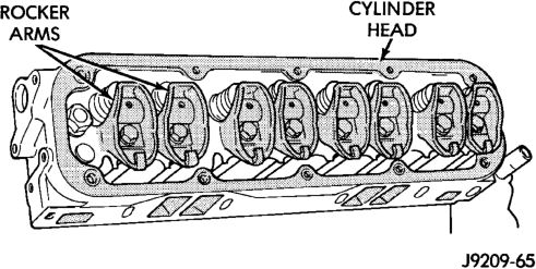
(2) Remove cylinder head cover and gasket. (3) Remove the rocker arm bolts and pivots (Fig. 18). Place them on a bench in the same order as removed.
(4) Remove the push rods and place them on a bench in the same order as removed.
INSTALLATION
(1) Rotate the crankshaft until the “V8” mark lines up with the TDC mark on the timing chain case cover. This mark is located 147° ATDC from the No.1 firing position.
(2) Install the push rods in the same order as removed.
(3) Install rocker arm and pivot assemblies in the same order as removed. Tighten the rocker arm bolts to 28 N·m (21 ft. lbs.) torque.
CAUTION: DO NOT rotate or crank the engine during or immediately after rocker arm installation. Allow the hydraulic roller tappets adequate time to bleed down (about 5 minutes).
(4) Install cylinder head cover. (5) Connect spark plug wires.
VALVE SPRING AND STEM SEAL REPLACEMENT- IN VEHICLE
(1) Set engine basic timing to Top Dead Center (TDC).
(2) Remove the air cleaner. (3) Remove cylinder head covers and spark plugs. (4) Remove coil wire from distributor and secure to good ground to prevent engine from starting.
(5) Using suitable socket and flex handle at crankshaft retaining bolt, turn engine so the No.1 piston is at TDC on the compression stroke.
(6) Remove rocker arms.
(7) With air hose attached to an adapter installed in No.1 spark plug hole, apply 620-689 kPa (90-100 psi) air pressure.
(8) Using Valve Spring Compressor Tool MD-998772A with adaptor 6716A, compress valve spring and remove retainer valve locks and valve spring.
(9) Install seals on the exhaust valve stem and position down against valve guides.
(10) The intake valve stem seals should be pushed firmly and squarely over the valve guide using the valve stem as a guide. DO NOT force seal against top of guide. When installing the valve retainer locks, compress the spring only enough to install the locks.
(11) Follow the same procedure on the remaining 7 cylinders using the firing sequence 1-8-4-3-6-5-7-2. Make sure piston in cylinder is at TDC on the valve spring that is being removed.
(12) Remove adapter from the No.1 spark plug hole.
(13) Install rocker arms. (14) Install covers and coil wire to distributor. (15) Install air cleaner. (16) Road test vehicle.
CYLINDER HEAD
REMOVAL
(1) Disconnect the battery negative cable. (2) Drain cooling system (refer to Group 7, Cooling System for the proper procedures).
(3) Remove the generator. (4) Remove closed crankcase ventilation system. (5) Disconnect the evaporation control system. (6) Remove the air cleaner. (7) Perform the Fuel System Pressure Release procedure (refer to Group 14, Fuel System). Disconnect the fuel supply line.
(8) Disconnect accelerator linkage and if so equipped, the speed control and transmission kickdown cables.
(9) Remove distributor cap and wires. (10) Disconnect the coil wires. (11) Disconnect heat indicator sending unit wire. (12) Disconnect heater hoses and bypass hose. (13) Remove cylinder head covers and gaskets. (14) Remove intake manifold and throttle body as an assembly. Discard the flange side gaskets and the front and rear cross-over gaskets.
(15) Remove exhaust manifolds. (16) Remove rocker arm assemblies and push rods. Identify to ensure installation in original locations.
(17) Remove the head bolts from each cylinder head and remove cylinder heads. Discard the cylinder head gasket.
(18) Remove spark plugs.
INSTALLATION
(1) Position the new cylinder head gaskets onto the cylinder block.
(2) Position the cylinder heads onto head gaskets and cylinder block.
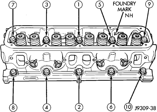
(3) Starting at top center, tighten all cylinder head bolts, in sequence, to 68 N·m (50 ft. lbs.) torque (Fig. 19). Repeat procedure, tighten all cylinder head bolts to 143 N·m (105 ft. lbs.) torque. Repeat procedure to confirm that all bolts are at 143 N·m (105 ft. lbs.) torque.
CAUTION: When tightening the rocker arm bolts, make sure the piston in that cylinder is NOT at TDC. Contact between the valves and piston could occur.
(4) Install push rods and rocker arm assemblies in their original position. Tighten the bolts to 28 N·m (21 ft. lbs.) torque.
(5) Install the intake manifold and throttle body assembly (refer to Group 11, Exhaust System and Intake Manifold).
(6) Install exhaust manifolds. Tighten the bolts and nuts to 34 N·m (25 ft. lbs.) torque.
(7) Adjust spark plugs to specifications (refer to Group 8D, Ignition System). Install the plugs and tighten to 41 N·m (30 ft. lbs.) torque.
(8) Install coil wires. (9) Connect heat indicator sending unit wire. (10) Connect the heater hoses and bypass hose. (11) Install distributor cap and wires. (12) Connect the accelerator linkage and if so equipped, the speed control and transmission kickdown cables.
(13) Install the fuel supply line. (14) Install the generator and drive belt. Tighten generator mounting bolt to 41 N·m (30 ft. lbs.) torque. Tighten the adjusting strap bolt to 23 N·m
(200 in. lbs.) torque. Refer to Group 7, Cooling System for adjusting the belt tension.
(15) Install the intake manifold-to-generator bracket support rod. Tighten the bolts.
(16) Place the cylinder head cover gaskets in position and install cylinder head covers. Tighten the bolts to 11 N·m (95 in. lbs.) torque.
(17) Install closed crankcase ventilation system. (18) Connect the evaporation control system. (19) Install the air cleaner. (20) Fill cooling system (refer to Group 7, Cooling System for proper procedure).
(21) Connect the negative cable to the battery.
VALVES AND VALVE SPRINGS
REMOVAL
(1) Remove the cylinder head. (2) Compress valve springs using Valve Spring Compressor Tool MD- 998772A and adapter 6716A.
(3) Remove valve retaining locks, valve spring retainers, valve stem seals and valve springs.
(4) Before removing valves, remove any burrs from valve stem lock grooves to prevent damage to the valve guides. Identify valves to ensure installation in original location.
INSTALLATION
(1) Clean valves thoroughly. Discard burned, warped and cracked valves.
(2) Remove carbon and varnish deposits from inside of valve guides with a reliable guide cleaner. (3) Measure valve stems for wear. If wear exceeds 0.051 mm (0.002 inch), replace the valve.
(4) Coat valve stems with lubrication oil and insert them in cylinder head.
(5) If valves or seats are reground, check valve stem height. If valve is too long, replace cylinder head.
(6) Install new seals on all valve guides. Install valve springs and valve retainers.
(7) Compress valve springs with Valve Spring Compressor Tool MD-998772A and adapter 6716A, install locks and release tool. If valves and/or seats are ground, measure the installed height of springs. Make sure the measurement is taken from bottom of spring seat in cylinder head to the bottom surface of spring retainer. If spacers are installed, measure from the top of spacer. If height is greater than 42.86 mm (1-11/16 inches), install a 1.587 mm (1/16 inch) spacer in head counterbore. This should bring spring height back to normal 41.27 to 42.86 mm (1-5/8 to 1-11/16 inch).
HYDRAULIC TAPPETS
REMOVAL
(1) Remove the air cleaner. (2) Remove cylinder head cover, rocker assembly and push rods. Identify push rods to ensure installation in original location.
(3) Remove intake manifold, yoke retainer and aligning yokes.
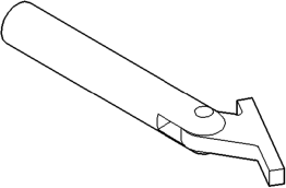
(4) Slide Hydraulic Tappet Remover/Installer Tool C-4129-A through opening in cylinder head and seat tool firmly in the head of tappet.
(5) Pull tappet out of bore with a twisting motion. If all tappets are to be removed, identify tappets to ensure installation in original location.
INSTALLATION
(1) If the tappet or bore in cylinder block is scored, scuffed, or shows signs of sticking, ream the bore to next oversize. Replace with oversize tappet.
(2) Lubricate tappets. (3) Install tappets and push rods in their original positions. Ensure that the oil feed hole in the side of the tappet body faces up (away from the crankshaft).
(4) Install aligning yokes with ARROW toward camshaft.
(5) Install yoke retainer. Tighten the bolts to 23 N·m (200 in. lbs.) torque. Install intake manifold.
(6) Install push rods in original positions. (7) Install rocker arm. (8) Install cylinder head cover. (9) Start and operate engine. Warm up to normal operating temperature.
CAUTION: To prevent damage to valve mechanism, engine must not be run above fast idle until all hydraulic tappets have filled with oil and have become quiet.
VIBRATION DAMPER
REMOVAL
(1) Disconnect the negative cable from the battery. (2) Remove fan shroud retainer bolts and set shroud back over engine.
(3) Remove the cooling system fan. (4) Remove the serpentine belt (refer to Group 7, Cooling System).
(5) Remove the vibration damper pulley. (6) Remove vibration damper bolt and washer from end of crankshaft.
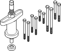
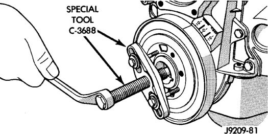
(7) Install bar and screw from Puller Tool Set C-3688. Install 2 bolts with washers through the puller tool and into the vibration damper (Fig. 20).
(8) Pull vibration damper off of the crankshaft.
INSTALLATION
(1) Position the vibration damper onto the crankshaft.
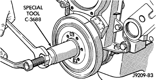
(2) Place installing tool, part of Puller Tool Set C-3688 in position and press the vibration damper onto the crankshaft (Fig. 21).
(3) Install the crankshaft bolt and washer. Tighten the bolt to 183 N·m (135 ft. lbs.) torque.
(4) Install the crankshaft pulley. Tighten the pulley bolts to 23 N·m (200 in. lbs.) torque.
(5) Install the serpentine belt (refer to Group 7, Cooling System).
(6) Install the cooling system fan. Tighten the bolts to 23 N·m (17 ft. lbs.) torque.
(7) Position the fan shroud and install the bolts. Tighten the retainer bolts to 11 N·m (95 in. lbs.) torque.
(8) Connect the negative cable to the battery.
TIMING CHAIN COVER
REMOVAL
(1) Disconnect the negative cable from the battery. (2) Drain cooling system (refer to Group 7, Cooling System).
(3) Remove the serpentine belt (refer to Group 7, Cooling System).
(4) Remove water pump (refer to Group 7, Cooling System).
(5) Remove power steering pump (refer to Group 19, Steering).
(6) Remove vibration damper. (7) Loosen oil pan bolts and remove the front bolt at each side.
(8) Remove the cover bolts. (9) Remove chain case cover and gasket using extreme caution to avoid damaging oil pan gasket.
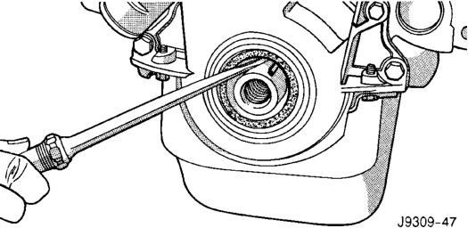
(10) Place a suitable tool behind the lips of the oil seal to pry the oil seal outward. Be careful not to damage the crankshaft seal surface of cover (Fig. 22).
INSTALLATION
(1) Using a new cover gasket, carefully install chain case cover to avoid damaging oil pan gasket. Use a small amount of Mopart Silicone Rubber Adhesive Sealant, or equivalent, at the joint between timing chain cover gasket and the oil pan gasket. Finger tighten the timing chain cover bolts at this time.
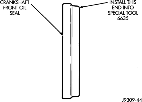
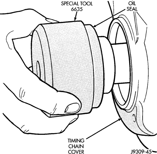
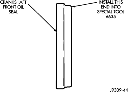
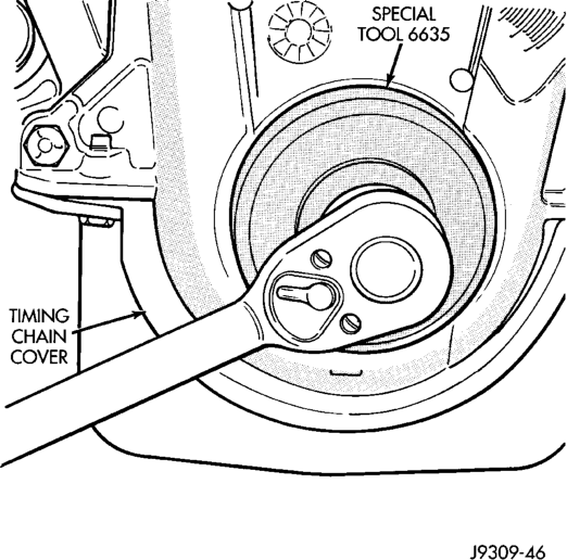
(2) Place the smaller diameter of the oil seal over Front Oil Seal Installation Tool 6635 (Fig. 23). Seat the oil seal in the groove of the tool.
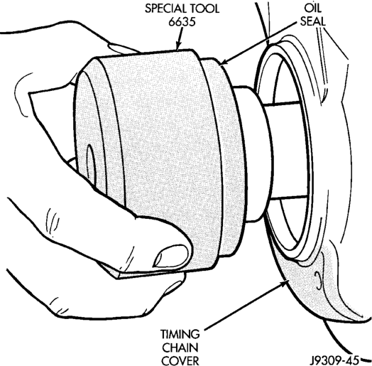
(3) Position the seal and tool onto the crankshaft (Fig. 24).
(4) Tighten the 4 lower chain case cover bolts to 13N·m (10 ft.lbs.) to prevent the cover from tipping during seal installation.
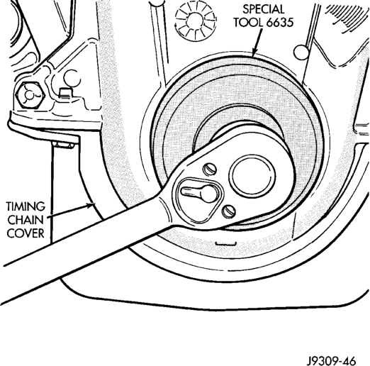
(5) Using the vibration damper bolt, tighten the bolt to draw the seal into position on the crankshaft (Fig. 25).
(6) Loosen the 4 bolts tightened in step 4 to allow realignment of front cover assembly.
(7) Tighten chain case cover bolts to 41 N·m (30 ft. lbs.) torque. Tighten oil pan bolts to 24 N·m (215 in. lbs.) torque.
(8) Remove the vibration damper bolt and seal installation tool.
(9) Install vibration damper. (10) Install water pump and housing assembly using new gaskets (refer to Group 7, Cooling System). Tighten bolts to 41 N·m (30 ft. lbs.) torque.
(11) Install power steering pump (refer to Group 19, Steering).
(12) Install the serpentine belt (refer to Group 7, Cooling System).
(13) Install the cooling system fan. Tighten the bolts to 23 N·m (17 ft. lbs.) torque.
(14) Position the fan shroud and install the bolts. Tighten the bolts to 11 N·m (95 in. lbs.) torque.
(15) Fill cooling system (refer to Group 7, Cooling System for the proper procedure).
(16) Connect the negative cable to the battery.
TIMING CHAIN
REMOVAL
(1) Remove Timing Chain Cover Refer to procedure in this section.
(2) Remove camshaft sprocket attaching bolt and remove timing chain with crankshaft and camshaft sprockets.
INSTALLATION
(1) Place both camshaft sprocket and crankshaft sprocket on the bench with timing marks on exact imaginary center line through both camshaft and crankshaft bores.
(2) Place timing chain around both sprockets. (3) Turn crankshaft and camshaft to line up with keyway location in crankshaft sprocket and in camshaft sprocket.
(4) Lift sprockets and chain (keep sprockets tight against the chain in position as described).
(5) Slide both sprockets evenly over their respective shafts and use a straightedge to check alignment of timing marks (Fig. 26).
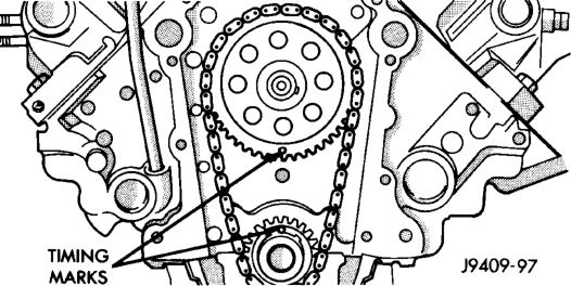
(6) Install the camshaft bolt. Tighten the bolt to 68 N·m (50 ft. lbs.) torque.
(7) Check camshaft end play. The end play should be 0.051-0.152 mm (0.002-0.006 inch) with a new thrust plate and up to 0.254 mm (0.010 inch) with a used thrust plate. If not within these limits install a new thrust plate.
CAMSHAFT
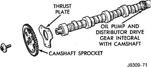
NOTE: The camshaft has an integral oil pump and distributor drive gear (Fig. 27).
REMOVAL
(1) Remove intake manifold. (2) Remove cylinder head covers. (3) Remove timing case cover and timing chain. (4) Remove rocker arms. (5) Remove push rods and tappets. Identify each part so it can be installed in its original location.
(6) Remove distributor and lift out the oil pump and distributor drive shaft.
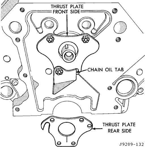
(7) Remove camshaft thrust plate, note location of oil tab (Fig. 28).
(8) Install a long bolt into front of camshaft to facilitate removal of the camshaft. Remove camshaft, being careful not to damage cam bearings with the cam lobes.
INSTALLATION
(1) Lubricate camshaft lobes and camshaft bearing journals and insert the camshaft to within 51 mm (2 inches) of its final position in cylinder block.
NOTE: Whenever an engine has been rebuilt, a new camshaft and/or new tappets installed, add 1 pint of Mopar Crankcase Conditioner, or equivalent. The oil mixture should be left in engine for a minimum of 805 km (500 miles). Drain at the next normal oil change.
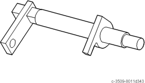
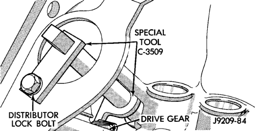
(2) Install Camshaft Gear Installer Tool C-3509 with tongue back of distributor drive gear (Fig. 29).
Position)
(3) Hold tool in position with a distributor lockplate bolt. This tool will restrict camshaft from being pushed in too far and prevent knocking out the welch plug in rear of cylinder block. Tool should remain installed until the camshaft and crankshaft sprockets and timing chain have been installed.
(4) Install camshaft thrust plate and chain oil tab. Make sure tang enters lower right hole in thrust plate. Tighten bolts to 24 N·m (210 in. lbs.) torque. Top edge of tab should be flat against thrust plate in order to catch oil for chain lubrication.
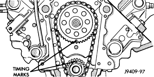
(5) Place both camshaft sprocket and crankshaft sprocket on the bench with timing marks on exact imaginary center line through both camshaft and crankshaft bores.
(6) Place timing chain around both sprockets. (7) Turn crankshaft and camshaft to line up with keyway location in crankshaft sprocket and in camshaft sprocket.
(8) Lift sprockets and chain (keep sprockets tight against the chain in position as described).
(9) Slide both sprockets evenly over their respective shafts and use a straightedge to check alignment of timing marks (Fig. 30).
(10) Install the camshaft bolt/cup washer. Tighten bolt to 68 N·m (50 ft. lbs.) torque.
(11) Measure camshaft end play. Refer to Specifications for proper clearance. If not within limits install a new thrust plate.
(12) Each tappet reused must be installed in the same position from which it was removed. When camshaft is replaced, all of the tappets must be replaced.
CAMSHAFT BEARINGS
REMOVAL
NOTE: This procedure requires that the engine is removed from the vehicle.
(1) With engine completely disassembled, drive out rear cam bearing core hole plug.
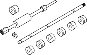
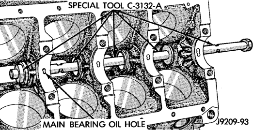
(2) Install proper size adapters and horseshoe washers (part of Camshaft Bearing Remover/Installer Tool C-3132-A) at back of each bearing shell. Drive out bearing shells (Fig. 31).
Tool C-3132-A
INSTALLATION
(1) Install new camshaft bearings with Camshaft Bearing Remover/Installer Tool C-3132-A by sliding the new camshaft bearing shell over proper adapter.
(2) Position rear bearing in the tool. Install horseshoe lock and by reversing removal procedure, carefully drive bearing shell into place.
(3) Install remaining bearings in the same manner. Bearings must be carefully aligned to bring oil holes into full register with oil passages from the main bearing. If the camshaft bearing shell oil holes are not in exact alignment, remove and install them correctly. Install a new core hole plug at the rear of camshaft. Be sure this plug does not leak.
CRANKSHAFT MAIN BEARINGS
REMOVAL
(1) Remove the oil pan. (2) Remove the oil pump from the rear main bearing cap. (3) Identify bearing caps before removal. Remove bearing caps one at a time.
(4) Remove upper half of bearing by inserting Crankshaft Main Bearing Remover/Installer Tool C-3059 into the oil hole of crankshaft (Fig. 32).
(5) Slowly rotate crankshaft clockwise, forcing out upper half of bearing shell.
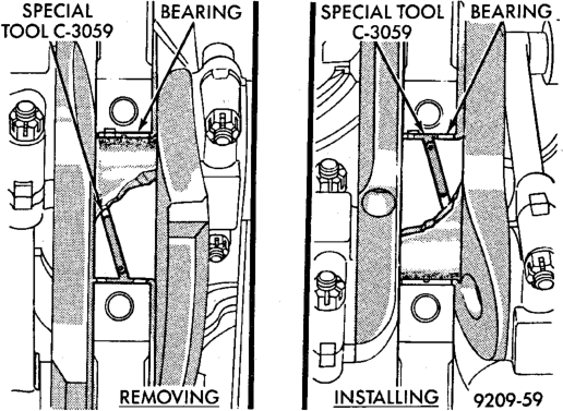
Installation with Tool C-3059
INSTALLATION
Only one main bearing should be selectively fitted while all other main bearing caps are properly tightened. All bearing capbolts removed during service procedures are to be cleaned and oiled before installation.
When installing a new upper bearing shell, slightly chamfer the sharp edges from the plain side.
(1) Start bearing in place, and insert Crankshaft Main Bearing Remover/Installer Tool C-3059 into oil hole of crankshaft (Fig. 32).
(2) Slowly rotate crankshaft counterclockwise sliding the bearing into position. Remove Tool C-3059.
(3) Install the bearing caps. Clean and oil the bolts. Tighten the capbolts to 115 N·m (85 ft. lbs.) torque.
(4) Install the oil pump. (5) Install the oil pan.
DISTRIBUTOR DRIVE SHAFT BUSHING
REMOVAL
(1) Remove distributor, refer to Group 8D, Ignition Systems for the proper procedure.
(2) Remove the intake manifold (refer to Group 11, Exhaust System and Intake Manifold).
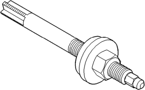
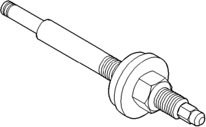
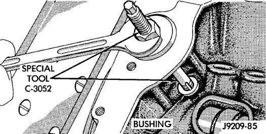
(3) Insert Distributor Drive Shaft Bushing Puller Tool C-3052 into old bushing and thread down until a tight fit is obtained (Fig. 33).
(4) Hold puller screw and tighten puller nut until bushing is removed.
INSTALLATION
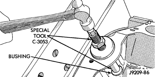
(1) Slide new bushing over burnishing end of Distributor Drive Shaft Bushing Driver/Burnisher Tool C-3053. Insert the tool and bushing into the bore.
(2) Drive bushing and tool into position, using a hammer (Fig. 34).
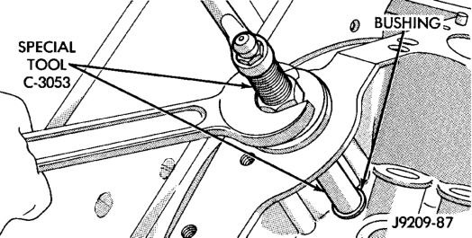
(3) As the burnisher is pulled through the bushing, the bushing is expanded tight in the block and burnished to correct size (Fig. 35). DO NOT ream this bushing.
CAUTION: This procedure MUST be followed when installing a new bushing or seizure to shaft may occur.
(4) Install the intake manifold (refer to Group 11, Exhaust System and Intake Manifold).
DISTRIBUTOR INSTALLATION
NOTE: Before installing the distributor, the oil pump drive shaft must be aligned to number one cylinder.
(1) Rotate crankshaft until No.1 cylinder is at top dead center on the firing stroke.
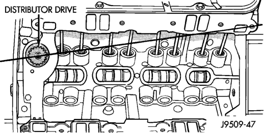
(2) When in this position, the timing mark of vibration damper should be under “0” on the timing indicator. (3) Install the shaft so that after the gear spirals into place, it will index with the oil pump shaft. The slot on top of oil pump shaft should be aligned towards the left front intake manifold attaching bolt hole (Fig. 36).
(4) Install distributor, refer to Group 8D, Ignition Systems for the proper procedure.
After the distributor has been installed, its rotational position must be set using the SET SYNC mode of the DRB scan tool. Refer to Checking Distributor Position following the Distributor Installation section in Group 8D, Ignition system.
Do not attempt to adjust ignition timing by rotating the distributor. It has no effect on ignition timing. Adjusting distributor position will effect fuel synchronization only.
OIL PAN
REMOVAL
(1) Disconnect the negative cable from the battery. (2) Raise the vehicle. (3) Remove the oil pan drain plug and drain the engine oil.
(4) Remove the oil filter. (5) Remove the starter (refer to Group 8B, Battery/ Starter/Generator Service).
(6) If equipped with an oil level sensor, disconnect the sensor.
(7) Position the cooler lines out of the way. (8) Disconnect the oxygen sensor. (9) Remove exhaust pipe. (10) Remove the oil pan bolts. Carefully slide the oil pan and gasket to the rear. If equipped with an oil level sensor, take care not to damage the sensor.
INSTALLATION
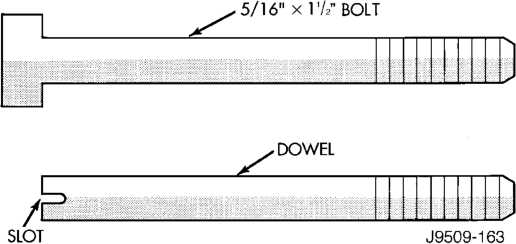
(1) Fabricate 4 alignment dowels from 5/16 x 1 1/2 inch bolts. Cut the head off the bolts and cut a slot into the top of the dowel. This will allow easier installation and removal with a screwdriver (Fig. 37).
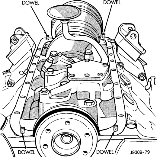
(2) Install the dowels in the cylinder block (Fig. 38).
(3) Apply small amount of Mopart Silicone Rubber Adhesive Sealant, or equivalent in the corner of the cap and the cylinder block.
(4) Slide the one-piece gasket over the dowels and onto the block.
(5) Position the oil pan over the dowels and onto the gasket. If equipped with an oil level sensor, take care not to damage the sensor.
(6) Install the oil pan bolts. Tighten the bolts to 24 N·m (215 in. lbs.) torque.
(7) Remove the dowels. Install the remaining oil pan bolts. Tighten these bolts to 24 N·m (215 in. lbs.) torque.
(8) Install the drain plug. Tighten drain plug to 34 N·m (25 ft. lbs.) torque.
(9) Install exhaust pipe. (10) Connect the oxygen sensor. (11) Install the oil filter. (12) If equipped with an oil level sensor, connect the sensor.
(13) Install the starter (refer to Group 8B, Battery/ Starter/Generator Service).
(14) Move the cooler lines back into position. (15) Lower vehicle. (16) Connect the negative cable to the battery. (17) Fill the oil pan with engine oil to the specified level.
WARNING: USE EXTREME CAUTION WHEN THE ENGINE IS OPERATING. DO NOT STAND IN A DIRECT LINE WITH THE FAN. DO NOT PUT YOUR HANDS NEAR THE PULLEYS, BELTS OR FAN. DO NOT WEAR LOOSE CLOTHING.
(18) Start the engine and inspect for leaks.
PISTON AND CONNECTING ROD ASSEMBLY
REMOVAL
(1) Remove the engine from the vehicle. (2) Remove the cylinder head. (3) Remove the oil pan. (4) Remove top ridge of cylinder bores with a reliable ridge reamer before removing pistons from cylinder block. Be sure to keep tops of pistons covered during this operation.
(5) Be sure the connecting rod and connecting rod cap are identified with the cylinder number. Remove connecting rod cap. Install connecting rod bolt guide set on connecting rod bolts.
(6) Pistons and connecting rods must be removed from top of cylinder block. When removing piston and connecting rod assemblies, rotate crankshaft to center the connecting rod in the cylinder bore and at BDC. Be careful not to nick crankshaft journals.
(7) After removal, install bearing cap on the mating rod.
INSTALLATION
(1) Be sure that compression ring gaps are staggered so that neither is in-line with oil ring rail gap.
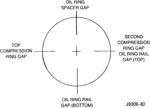
(2) Before installing the ring compressor, make sure the oil ring expander ends are butted and the rail gaps located properly (Fig. 39).
(3) Immerse the piston head and rings in clean engine oil. Slide Piston Ring Compressor Tool C-385 over the piston and tighten with the special wrench (part of Tool C-385). Be sure position of rings does not change during this operation.
(4) Install connecting rod bolt protectors on rod bolts, the long protector should be installed on the numbered side of the connecting rod.
(5) Rotate crankshaft so that the connecting rod journal is on the center of the cylinder bore. Be sure connecting rod and cylinder bore number are the same. Insert rod and piston into cylinder bore and guide rod over the crankshaft journal.
(6) Tap the piston down in cylinder bore, using a hammer handle. At the same time, guide connecting rod into position on crankshaft journal.
(7) The notch or groove on top of piston must be pointing toward front of engine. The larger chamfer of the connecting rod bore must be installed toward crankshaft journal fillet.
(8) Install rod caps. Be sure connecting rod, connecting rod cap and cylinder bore number are the same. Install nuts on cleaned and oiled rod bolts and tighten nuts to 61 N·m (45 ft. lbs.) torque.
(9) Install the oil pan. (10) Install the cylinder head. (11) Install the engine into the vehicle.
CRANKSHAFT
REMOVAL
(1) Remove the oil pan. (2) Remove the oil pump from the rear main bearing cap. (3) Remove the vibration damper. (4) Remove the timing chain cover. (5) Identify bearing caps before removal. Remove bearing caps and bearings one at a time.
(6) Lift the crankshaft out of the block. (7) Remove and discard the crankshaft rear oil seals.
(8) Remove and discard the front crankshaft oil seal.
INSTALLATION
(1) Clean Loctite 518 residue and sealant from the cylinder block and rear cap mating surface. Do this before applying the Loctite drop and the installation of rear cap.
(2) Lightly oil the new upper seal lips with engine oil.
(3) Install the new upper rear bearing oil seal with the white paint facing towards the rear of the engine.
(4) Position the crankshaft into the cylinder block. (5) Lightly oil the new lower seal lips with engine oil.
(6) Install the new lower rear bearing oil seal into the bearing cap with the white paint facing towards the rear of the engine.
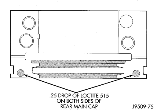
(7) Apply 5 mm (0.20 in) drop of Loctite 518, or equivalent, on each side of the rear main bearing cap (Fig. 40). DO NOT over apply sealant or allow the sealant to contact the rubber seal. Assemble bearing cap to cylinder block immediately after sealant application.
(8) To align the bearing cap, use cap slot, alignment dowel and cap bolts. DO NOT remove excess material after assembly. DO NOT strike rear cap more than 2 times for proper engagement.
(9) Clean and oil all cap bolts. Install all main bearing caps. Install all cap bolts and alternately tighten to 115 N·m (85 ft. lbs.) torque.
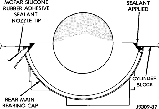
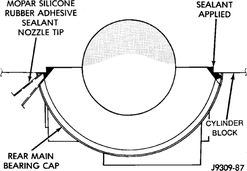
(10) Install oil pump. (11) Install the timing chain cover. (12) Install the vibration damper. (13) Apply Mopart Silicone Rubber Adhesive Sealant, or equivalent, at bearing cap to block joint to
provide cap to block and oil pan sealing (Fig. 41). Apply enough sealant until a small amount is squeezed out. Withdraw nozzle and wipe excess sealant off the oil pan seal groove.
(14) Install new front crankshaft oil seal. (15) Immediately install the oil pan.
OIL PUMP
REMOVAL
(1) Remove the oil pan. (2) Remove the oil pump from rear main bearing cap.
INSTALLATION
(1) Install oil pump. During installation slowly rotate pump body to ensure driveshaft-to-pump rotor shaft engagement.
(2) Hold the oil pump base flush against mating surface on No.5 main bearing cap. Finger tighten pump attaching bolts. Tighten attaching bolts to 41 N·m (30 ft. lbs.) torque.
(3) Install the oil pan.
CRANKSHAFT OIL SEAL — FRONT
The oil seal can be replaced without removing the timing chain cover provided the cover is not misaligned.
(1) Disconnect the negative cable from the battery. (2) Remove vibration damper. (3) If front seal is suspected of leaking, check front oil seal alignment to crankshaft. The seal installation/alignment tool 6635, should fit with minimum interference. If tool does not fit, the cover must be removed and installed properly.
(4) Place a suitable tool behind the lips of the oil seal to pry the oil seal outward. Be careful not to damage the crankshaft seal bore of cover.
(5) Place the smaller diameter of the oil seal over Front Oil Seal Installation Tool 6635 (Fig. 42). Seat the oil seal in the groove of the tool.
(6) Position the seal and tool onto the crankshaft (Fig. 43).
(7) Using the vibration damper bolt, tighten the bolt to draw the seal into position on the crankshaft (Fig. 44).
(8) Remove the vibration damper bolt and seal installation tool. (9) Inspect the seal flange on the vibration damper.
(10) Install the vibration damper. (11) Connect the negative cable to the battery.
CRANKSHAFT OIL SEALS — REAR
The service seal is a 2 piece, viton seal. The upper seal half can be installed with crankshaft removed from engine or with crankshaft installed. When a new upper seal is installed, install a new lower seal. The lower seal half can only be installed with the rear main bearing cap removed.
UPPER SEAL —CRANKSHAFT REMOVED
REMOVAL
(1) Remove the crankshaft. Discard the old upper seal.
INSTALLATION
(1) Clean the cylinder block rear cap mating surface. Make sure the seal groove is free of debris.
(2) Lightly oil the new upper seal lips with engine oil.
(3) Install the new upper rear bearing oil seal with the white paint facing towards the rear of the engine.
(4) Position the crankshaft into the cylinder block. (5) Lightly oil the new lower seal lips with engine oil.
(6) Install the new lower rear bearing oil seal into the bearing cap with the white paint facing towards the rear of the engine.
(7) Apply 5 mm (0.20 in) drop of Loctite 518, or equivalent, on each side of the rear main bearing cap (Fig. 45). DO NOT over apply sealant or allow the sealant to contact the rubber seal. Assemble bearing cap to cylinder block immediately after sealant application.
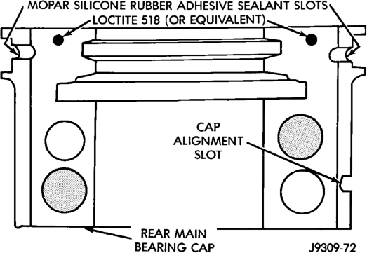
(8) To align the bearing cap, use cap slot, alignment dowel and cap bolts. DO NOT remove excess material after assembly. DO NOT strike rear cap more than 2 times for proper engagement.
(9) Clean and oil all cap bolts. Install all main bearing caps. Install all cap bolts and alternately tighten to 115 N·m (85 ft. lbs.) torque.
(10) Install oil pump. (11) Apply Mopar Silicone Rubber Adhesive Sealant, or equivalent, at bearing cap to block joint to provide cap to block and oil pan sealing (Fig. 46). Apply enough sealant until a small amount is squeezed out. Withdraw nozzle and wipe excess sealant off the oil pan seal groove.
(12) Install new front crankshaft oil seal. (13) Immediately install the oil pan.
UPPER SEAL —CRANKSHAFT INSTALLED
REMOVAL
(1) Remove the oil pan. (2) Remove the oil pump from the rear main bearing cap.
(3) Remove the rear main bearing cap. Remove and discard the old lower oil seal.
(4) Carefully remove and discard the old upper oil seal.
INSTALLATION
(1) Clean the cylinder block mating surfaces before oil seal installation. Check for burr at the oil hole on the cylinder block mating surface to rear cap.
(2) Lightly oil the new upper seal lips with engine oil. To allow ease of installation of the seal, loosen at least the 2 main bearing caps forward of the rear bearing cap.
(3) Rotate the new upper seal into the cylinder block being careful not to shave or cut the outer surface of the seal. To assure proper installation, use the installation tool provided with the kit. Install the new seal with the white paint facing towards the rear of the engine.
(4) Install the new lower rear bearing oil seal into the bearing cap with the white paint facing towards the rear of the engine.
(5) Apply 5 mm (0.20 in) drop of Loctite 518, or equivalent, on each side of the rear main bearing cap (Fig. 45). DO NOT over apply sealant or allow the sealant to contact the rubber seal. Assemble bearing cap to cylinder block immediately after sealant application. Be sure the white paint faces toward the rear of the engine.
(6) To align the bearing cap, use cap slot, alignment dowel and cap bolts. DO NOT remove excess material after assembly. DO NOT strike rear cap more than 2 times for proper engagement.
(7) Install the rear main bearing cap with cleaned and oiled cap bolts. Alternately tighten ALL cap bolts to 115 N·m (85 ft. lbs.) torque.
(8) Install oil pump. (9) Apply Mopar Silicone Rubber Adhesive Sealant, or equivalent, at bearing cap to block joint to provide cap to block and oil pan sealing (Fig. 46). Apply enough sealant until a small amount is squeezed out. Withdraw nozzle and wipe excess sealant off the oil pan seal groove.
(10) Immediately install the oil pan.
LOWER SEAL
REMOVAL
(1) Remove the oil pan. (2) Remove the oil pump from the rear main bearing cap. (3) Remove the rear main bearing cap and discard the old lower seal.
INSTALLATION
(1) Clean the rear main cap mating surfaces including the oil pan gasket groove. (2) Carefully install a new upper seal (refer to Upper Seal Replacement - Crankshaft Installed procedure above).
(3) Lightly oil the new lower seal lips with engine oil.
(4) Install a new lower seal in bearing cap with the white paint facing the rear of engine.
(5) Apply 5 mm (0.20 in) drop of Loctite 518, or equivalent, on each side of the rear main bearing cap (Fig. 45). DO NOT over apply sealant or allow the sealant to contact the rubber seal. Assemble bearing cap to cylinder block immediately after sealant application.
(6) To align the bearing cap, use cap slot, alignment dowel and cap bolts. DO NOT remove excess material after assembly. DO NOT strike rear cap more than 2 times for proper engagement.
(7) Install the rear main bearing cap with cleaned and oiled cap bolts. Alternately tighten the cap bolts to 115 N·m (85 ft. lbs.) torque.
(8) Install oil pump. (9) Apply Mopar Silicone Rubber Adhesive Sealant, or equivalent, at bearing cap to block joint to provide cap to block and oil pan sealing (Fig. 46). Apply enough sealant until a small amount is squeezed out. Withdraw nozzle and wipe excess sealant off the oil pan seal groove.
(10) Immediately install the oil pan.
ENGINE CORE OIL AND CAMSHAFT PLUGS
Engine core plugs have been pressed into the oil galleries behind the camshaft thrust plate (Fig. 47). This will reduce internal leakage and help maintain higher oil pressure at idle.
REMOVAL
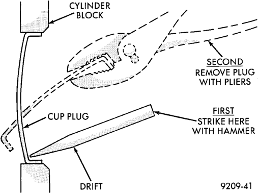
(1) Using a blunt tool such as a drift or a screwdriver and a hammer, strike the bottom edge of the cup plug (Fig. 48).
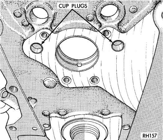
(2) With the cup plug rotated, grasp firmly with pliers or other suitable tool and remove plug (Fig. 48).
INSTALLATION
Thoroughly clean inside of cup plug hole in cylinder block or head. Be sure to remove old sealer.
Be certain the new plug is cleaned of all oil or grease.
(1) Coat edges of plug and core hole with Mopar Gasket Maker, or equivalent.
CAUTION: DO NOT drive cup plug into the casting, as restricted coolant flow can result and cause serious engine problems.
(2) Using proper plug drive, drive cup plug into hole. The sharp edge of the plug should be at least 0.50 mm (0.020 in.) inside the lead-in chamfer.
(3) It is not necessary to wait for curing of the sealant. The cooling system can be filled and the vehicle placed in service immediately.
DISASSEMBLY AND ASSEMBLY
HYDRAULIC TAPPETS
CAUTION: The plunger and tappet bodies are not interchangeable. The plunger and valve must always be fitted to the original body. It is advisable to work on one tappet at a time to avoid mixing of parts. Mixed parts are not compatible. DO NOT disassemble a tappet on a dirty work bench.
DISASSEMBLE
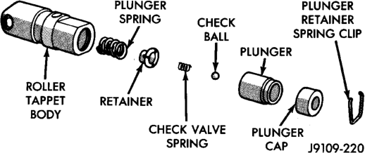
(1) Pry out plunger retainer spring clip (Fig. 49). (2) Clean varnish deposits from inside of tappet body above plunger cap.
(3) Invert tappet body and remove plunger cap, plunger, check valve, check valve spring, check valve retainer and plunger spring (Fig. 49). Check valve could be flat or ball.
ASSEMBLE
(1) Clean all tappet parts in a solvent that will remove all varnish and carbon.
(2) Replace tappets that are unfit for further service with new assemblies.
(3) If plunger shows signs of scoring or wear, install a new tappet assembly. If valve is pitted, or valve seat on end of plunger is prevented from seating, install a new tappet assembly. (4) Assemble tappets (Fig. 49).
VALVE SERVICE
VALVE GUIDES
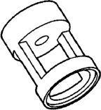
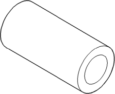
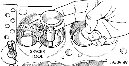
Measure valve stem guide clearance as follows: (1) Install Valve Guide Sleeve Tool C-3973 over valve stem and install valve (Fig. 50). The special sleeve places the valve at the correct height for checking with a dial indicator.
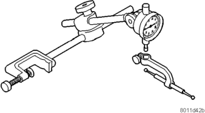
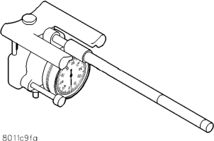
(2) Attach Dial Indicator Tool C-3339 to cylinder head and set it at right angle of valve stem being measured (Fig. 51).
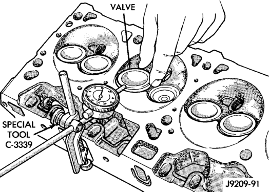
(3) Move valve to and from the indicator. The total dial indicator reading should not exceed 0.432 mm (0.017 inch). Ream the guides for valves with oversize stems if dial indicator reading is excessive or if the stems are scuffed or scored.
(4) Service valves with oversize stems are available (Fig. 52).
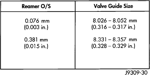
(5) Slowly turn reamer by hand and clean guide thoroughly before installing new valve. Ream the valve guides from standard to 0.381 mm (0.015 inch). Use a 2 step procedure so the valve guides are reamed true in relation to the valve seat:
• Step 1—Ream to 0.0763 mm (0.003 inch). • Step 2—Ream to 0.381 mm (0.015 inch).
REFACING VALVES AND VALVE SEATS
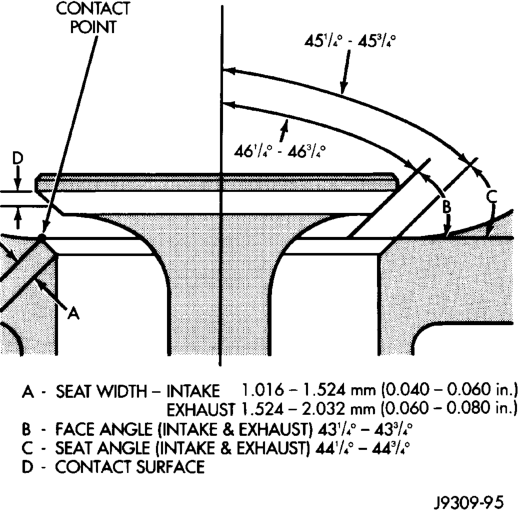
The intake and exhaust valves have a 43-1/4° to 43-3/4° face angle and a 44-1/4° to 44-3/4° seat angle (Fig. 53).
VALVES
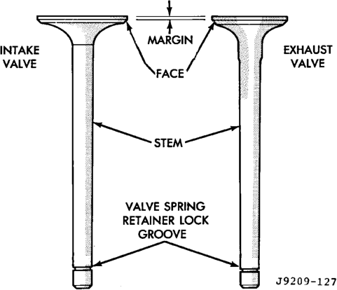
Inspect the remaining margin after the valves are refaced (Fig. 54). Valves with less than 1.190 mm (0.047 inch) margin should be discarded.
VALVE SEATS
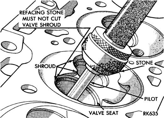
CAUTION: DO NOT un-shroud valves during valve seat refacing (Fig. 55).
(1) When refacing valve seats, it is important that the correct size valve guide pilot be used for reseating stones. A true and complete surface must be obtained.
(2) Measure the concentricity of valve seat using a dial indicator. Total runout should not exceed 0.051 mm (0.002 inch) total indicator reading.
(3) Inspect the valve seat with Prussian blue to determine where the valve contacts the seat. To do this, coat valve seat LIGHTLY with Prussian blue then set valve in place. Rotate the valve with light pressure. If the blue is transferred to the center of
valve face, contact is satisfactory. If the blue is transferred to the top edge of valve face, lower valve seat with a 15° stone. If the blue is transferred to bottom edge of valve face raise valve seat with a 60° stone.
(4) When seat is properly positioned the width of intake seats should be 1.016-1.524 mm (0.040-0.060 inch). The width of the exhaust seats should be 1.524-2.032 mm (0.060-0.080 inch).
VALVE SPRING INSPECTION
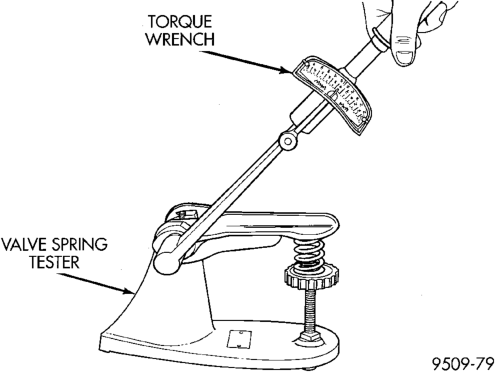
Whenever valves have been removed for inspection, reconditioning or replacement, valve springs should be tested. As an example the compression length of the spring to be tested is 1-5/16 inch. Turn table of Universals Valve Spring Tester Tool until surface is in line with the 1-5/16 inch mark on the threaded stud. Be sure the zero mark is to the front (Fig. 56). Place spring over stud on the table and lift compressing lever to set tone device. Pull on torque wrench until ping is heard. Take reading on torque wrench at this instant. Multiply this reading by 2. This will give the spring load at test length. Fractional measurements are indicated on the table for finer adjustments. Refer to specifications to obtain specified height and allowable tensions. Discard the springs that do not meet specifications.
Length
OIL PUMP
DISASSEMBLE
(1) Remove the relief valve as follows:
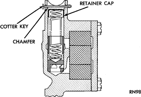
(a) Remove cotter pin. Drill a 3.175 mm (1/8 inch) hole into the relief valve retainer cap and insert a self-threading sheet metal screw. (b) Clamp screw into a vise and while supporting oil pump, remove cap by tapping pump body using a soft hammer. Discard retainer cap and remove spring and relief valve (Fig. 57).
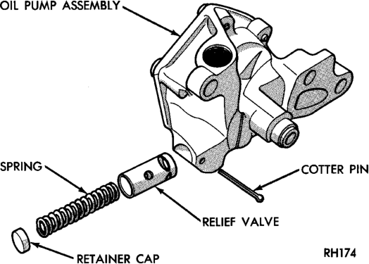
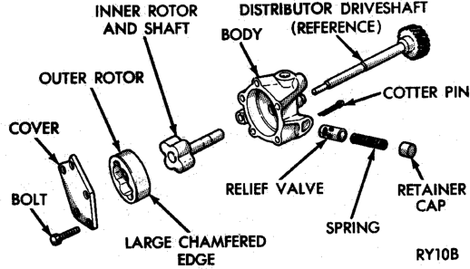
(2) Remove oil pump cover (Fig. 58). (3) Remove pump outer rotor and inner rotor with shaft (Fig. 58).
(4) Wash all parts in a suitable solvent and inspect carefully for damage or wear.
ASSEMBLE
(1) Install pump rotors and shaft, using new parts as required.
(2) Position the oil pump cover onto the pump body. Tighten cover bolts to 11 N·m (95 in. lbs.) torque.
(3) Install the relief valve and spring. Insert the cotter pin.
(4) Tap on a new retainer cap. (5) Prime oil pump before installation by filling rotor cavity with engine oil.
CYLINDER BLOCK
DISASSEMBLE
Engine assembly removed from vehicle: (1) Remove the cylinder head. (2) Remove the oil pan. (3) Remove the piston and connecting rod assemblies.
ASSEMBLE
(1) Install the piston and connecting rod assembly. (2) Install the oil pan. (3) Install the cylinder head. (4) Install the engine into the vehicle.
CLEANING AND INSPECTION
CYLINDER HEADS
CLEANING
Clean all surfaces of cylinder block and cylinder heads.
Clean cylinder block front and rear gasket surfaces using a suitable solvent.
INSPECTION
Inspect all surfaces with a straightedge if there is any reason to suspect leakage. If out-of-flatness exceeds 0.00075 mm/mm (0.00075 inch/inch) times the span length in inches in any direction, either replace head or lightly machine the head surface.
FOR EXAMPLE: A 305 mm (12 inch) span is 0.102 mm (0.004 inch) out-of-flat. The allowable outof-flat is 305 x 0.00075 (12 x 0.00075) equals 0.23 mm (0.009 inch). This amount of out-of-flat is acceptable.
The cylinder head surface finish should be 1.78-3.00 microns (70-125 micro inches).
Inspect push rods. Replace worn or bent rods.
PISTON AND CONNECTING ROD ASSEMBLY
INSPECTION
Check the crankshaft connecting rod journal for excessive wear, taper and scoring.
Check the cylinder block bore for out-of-round, taper, scoring and scuffing.
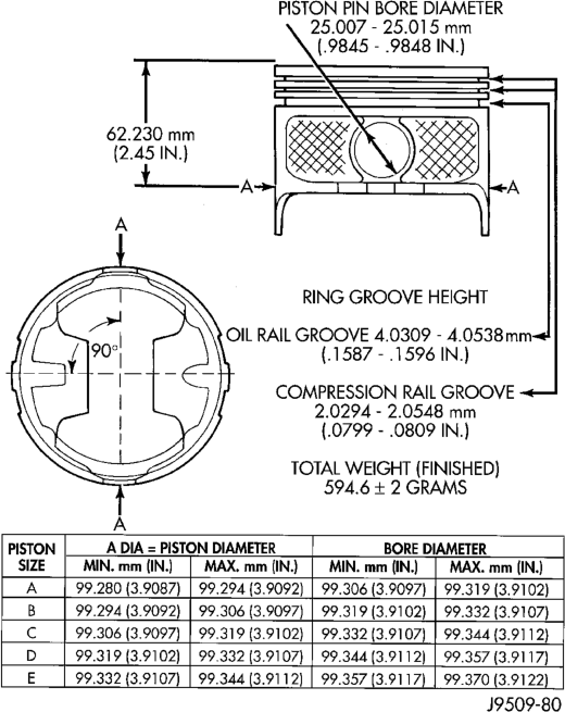
Check the pistons for taper and elliptical shape before they are fitted into the cylinder bore (Fig. 59).
CRANKSHAFT JOURNALS
The crankshaft connecting rod and main journals should be checked for excessive wear, taper and scoring. The maximum taper or out-of-round on any crankshaft journal is 0.025 mm (0.001 inch).
Journal grinding should not exceed 0.305 mm (0.012 inch) under the standard journal diameter. DO NOT grind thrust faces of No.3 main bearing. DO NOT nick crank pin or bearing fillets. After grinding, remove rough edges from crankshaft oil holes and clean out all oil passages.
CAUTION: After any journal grind, it is important that the final paper or cloth polish be in the same direction as the engine rotates.
OIL PAN
CLEANING
Clean the block and pan gasket surfaces. Trim or remove excess sealant film in the rear main cap oil pan gasket groove. DO NOT remove the sealant inside the rear main cap slots.
If present, trim excess sealant from inside the engine.
Clean oil pan in solvent and wipe dry with a clean cloth.
Clean oil screen and pipe thoroughly in clean solvent. Inspect condition of screen.
INSPECTION
Inspect oil drain plug and plug hole for stripped or damaged threads. Repair as necessary.
Inspect oil pan mounting flange for bends or distortion. Straighten flange, if necessary.
OIL PUMP
INSPECTION
Mating surface of the oil pump cover should be smooth. Replace pump assembly if cover is scratched or grooved.
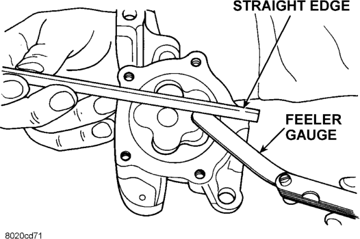
Lay a straightedge across the pump cover surface (Fig. 60). If a 0.038 mm (0.0015 inch) feeler gauge can be inserted between cover and straightedge, pump assembly should be replaced.
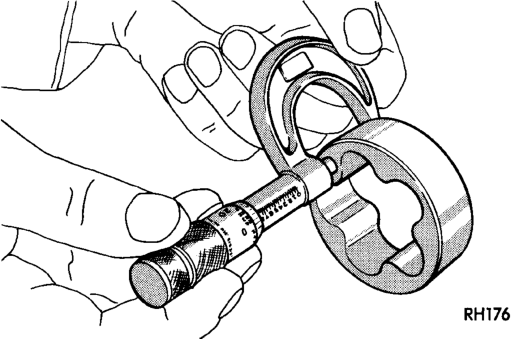
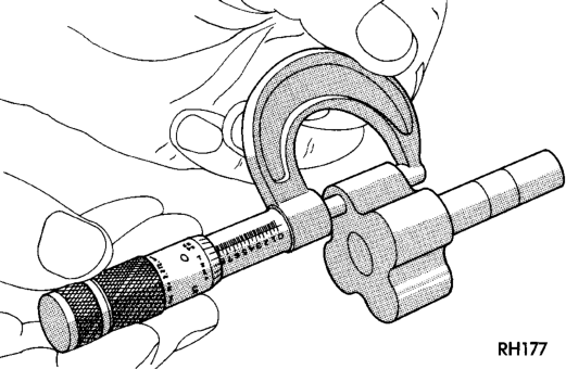
Measure thickness and diameter of OUTER rotor. If outer rotor thickness measures 20.9 mm (0.825 inch) or less or if the diameter is 62.7 mm (2.469 inches) or less, replace outer rotor (Fig. 61). If inner rotor measures 20.9 mm (0.825 inch) or less, replace inner rotor and shaft assembly (Fig. 62).
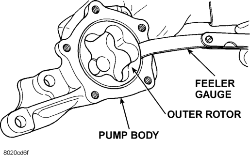
Slide outer rotor into pump body. Press rotor to the side with your fingers and measure clearance between rotor and pump body (Fig. 63). If clearance is 0.356 mm (0.014 inch) or more, replace oil pump assembly.
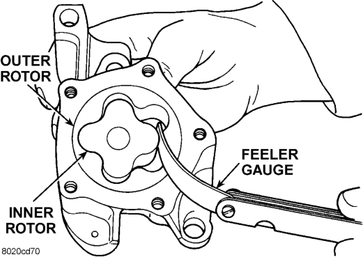
Install inner rotor and shaft into pump body. If clearance between inner and outer rotors is 0.203 mm (0.008 inch) or more, replace shaft and both rotors (Fig. 64).
Place a straightedge across the face of the pump, between bolt holes. If a feeler gauge of 0.102 mm (0.004 inch) or more can be inserted between rotors and the straightedge, replace pump assembly (Fig. 65).
Housing
Inspect oil pressure relief valve plunger for scoring and free operation in its bore. Small marks may be removed with 400-grit wet or dry sandpaper.
The relief valve spring has a free length of approximately 49.5 mm (1.95 inches). The spring should test between 19.5 and 20.5 pounds when compressed to 34 mm (1-11/32 inches). Replace spring that fails to meet these specifications (Fig. 66).
If oil pressure was low and pump is within specifications, inspect for worn engine bearings or other reasons for oil pressure loss.
CYLINDER BLOCK
CLEANING
Clean cylinder block thoroughly and check all core hole plugs for evidence of leaking.
INSPECTION
Examine block for cracks or fractures. The cylinder walls should be checked for out-ofround and taper with Cylinder Bore Indicator Tool C-119. The cylinder block should be bored and honed with new pistons and rings fitted if:
• The cylinder bores show more than 0.127 mm (0.005 in.) out-of-round.
• The cylinder bores show a taper of more than 0.254 mm (0.010 in.).
• The cylinder walls are badly scuffed or scored. Boring and honing operation should be closely coordinated with the fitting of pistons and rings, so that specified clearances can be maintained.
OIL LINE PLUG
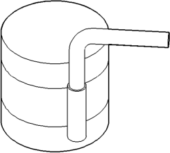
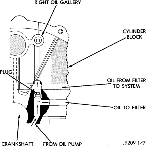
The oil line plug is located in the vertical passage at the rear of the block between the oil-to-filter and oil-from-filter passages (Fig. 67). Improper installation or plug missing could cause erratic, low, or no oil pressure.
The oil plug must come out the bottom. Use flat dowel, down the oil pressure sending unit hole from the top, to remove oil plug.
(1) Remove oil pressure sending unit from back of block.
(2) Insert a 3.175 mm (1/8 in.) finish wire, or equivalent, into passage.
(3) Plug should be 190.0 to 195.2 mm (7-1/2 to 7-11/16 in.) from machined surface of block (Fig. 67). If plug is too high, use a suitable flat dowel to position properly.
(4) If plug is too low, remove oil pan and No. 4 main bearing cap. Use suitable flat dowel to position properly. Coat outside diameter of plug with Mopar Stud and Bearing Mount Adhesive, or equivalent. Plug should be 54.0 to 57.7 mm (2-1/8 to 2-5/16 in.) from bottom of the block.
SPECIFICATIONS
5.2L ENGINE SPECIFICATIONS
GENERAL INFORMATION
Engine Type. . . . . . . . . . . . . . . . . . . . . .90° V-8 OHV Bore and Stroke . . . .99.3 x 84.0 mm (3.91 x 3.31 in.) Displacement . . . . . . . . . . . . . . . . . . . .5.2L (318 c.i.) Compression Ratio . . . . . . . . . . . . . . . . . . . . . . .9.1:1 Firing Order. . . . . . . . . . . . . . . . . .1–8–4–3–6–5–7–2 Lubrication . . . .Pressure Feed—Full Flow Filtration Cooling System. . .Liquid Cooled—Forced Circulation Cylinder Block. . . . . . . . . . . . . . . . . . . . . . .Cast Iron Crankshaft. . . . . . . . . . . . . . . . . . . . . . .Nodular Iron Cylinder Head . . . . . . . . . . . . . . . . . . . . . . .Cast Iron Combustion Chambers . . . . .Wedge-High Swirl Valve shrouding Camshaft. . . . . . . . . . . . . . . . . . . .Nodular Cast Iron Pistons . . . . . . . . . . . . . . . . .Aluminum Alloy w/strut Connecting Rods. . . . . . . . . . . . . . . . . . .Forged Steel
CAMSHAFT
Bearing Diameter No. 1 . . . . . . .50.800 – 50.825 mm (2.000 – 2.001 in.) No. 2 . . . . . . .50.394 – 50.419 mm (1.984 – 1.985 in.) No. 3 . . . . . . .50.013 – 50.038 mm (1.969 – 1.970 in.) No. 4 . . . . . . .49.606 – 49.632 mm (1.953 – 1.954 in.) No. 5 . . . . .39.688 – 39.713 mm (1.5625 – 1.5635 in.) Bearing Journal Diameter No. 1 . . . . . . .50.749 – 50.775 mm (1.998 – 1.999 in.) No. 2 . . . . . . .50.343 – 50.368 mm (1.982 – 1.983 in.) No. 3 . . . . . . .49.962 – 49.987 mm (1.967 – 1.968 in.) No. 4 . . . . . . .49.555 – 49.581 mm (1.951 – 1.952 in.) No. 5 . . . . .39.637 – 39.662 mm (1.5605 – 1.5615 in.) Bearing to Journal Clearance Standard . . . .0.0254 – 0.0762 mm (0.001 – 0.003 in.)
Service Limit . . . . . . . . . . . . .0.127 mm (0.005 in.) Camshaft End Play End Play . . . . . .0.051 – 0.254 mm (0.002 – 0.010 in.)
CONNECTING RODS
Piston Pin bore Diameter . . . . . .24.966 – 24.978 mm
(0.9829 – 0.9834 in.) Side Clearance . . . . . . . . . . . . . . . .0.152 – 0.356 mm
(0.006 – 0.014 in.)
CRANKSHAFT
Rod Journal Diameter . . . .53.950 – 53.975 mm (2.124 – 2.125 in.) Out of Round (Max.). . . . . . . . .0.0254 mm (0.001 in.)
Rod Journal Taper (Max.). . . . . . . . . . . . . . .0.0254 mm (0.001 in.) Bearing Clearance . . . . . . . . . . . . .0.013 – 0.056 mm
(0.0005 – 0.0022 in.) Service Limit . . . . . . . . . . . .0.0762 mm (0.003 in.) Main Bearing Journal Diameter. . .63.487 – 63.513 mm (2.4995 – 2.5005in.) Out of Round (Max.) . . . . . . . . .0.127 mm (0.001 in.) Taper (Max.). . . . . . . . . . . . . . .0.0254 mm (0.001 in.) Bearing Clearance (#1 Journal) . . .0.013 – 0.038 mm
(0.0005 – 0.0015 in.) Service Limit (#1 Journal) . . . . . . . . . . .0.0381 mm
(0.0015 in.) Bearing Clearance
(#2-5 Journals) . . . . . . . . . . . . . .0.013 – 0.051 mm
(0.0005 – 0.002 in.) Service Limit (#2-5 Journals) . . . . . . . . .0.064 mm
(0.0025 in.) Crankshaft End Play End Play . . . . . .0.051 – 0.178 mm (0.002 – 0.007 in.)
Service Limit . . . . . . . . . . . . .0.254 mm (0.010 in.)
CYLINDER BLOCK
Cylinder Bore Diameter . . . .99.314 – 99.365 mm (3.910 – 3.912 in.) Out of Round (Max.) . . . . . . . . .0.127 mm (0.005 in.) Taper (Max.) . . . . . . . . . . . . . . .0.254 mm (0.010 in.) Oversize Limit . . . . . . . . . . . . . .1.016 mm (0.040 in.) Lifter Bore Diameter . . . . . . . . . . . . . . . . . . . .22.99 – 23.01 mm
(0.9051 – 0.9059 in.) Distributor Drive Bushing (Press Fit) Bushing to Bore Interference . . .0.0127 – 0.3556 mm
(0.0005 – 0.0140 in.) Shaft to Bushing Clearance . . . .0.0178 – 0.0686 mm
(0.0007 – 0.0027 in.)
CYLINDER HEAD AND VALVES
Valve Seat Angle . . . . . . . . . . . . . . . . . . . . . . . . .44.25° – 44.75° Runout (Max.) . . . . . . . . . . . . .0.0762 mm (0.003 in.) Width (Finish) – Intake . . . . . . . . .1.016 – 1.524 mm
(0.040 – 0.060 in.) Width (Finish) – Exhaust . . . . . . . .1.524 – 2.032 mm
(0.060 – 0.080 in.) Valves Face Angle . . . . . . . . . . . . . . . . . . . . .43.25° – 43.75° Head Diameter – Intake . . . . .48.666 mm (1.916 in.) Head Diameter – Exhaust. . . . . . . .41.250 (1.624 in.) Length (Overall) – Intake . . . . . .124.28 – 125.92 mm
(4.893 – 4.918 in.) Length (Overall) – Exhaust . . . .124.64 – 125.27 mm
(4.907 – 4.932 in.) Lift (@ zero lash) . . . . . . . . . . .10.973 mm (0.432 in.)
Stem Diameter .. .7.899 — 7.925 mm (0.311 — 0.312 in.)
Valve Seat Guide Bore . . . . . . . . . . . . . . . . . . .7.950 – 7.976 mm
(0.313 – 0.314 on.) Stem to Guide Clearance . . . . . .0.0254 – 0.0762 mm
(0.001 – 0.003 in.) Service Limit (rocking method) . .0.4318 (0.017 in.) Valve Springs Free Length . . . . . . . . . . . . . . .49.962 mm (1.967 in.) Spring Tension – (valve closed) . .378 N @ 41.66 mm
(85 lbs. @ 1.64 in.) Spring Tension – (valve open). . . .890 N @ 30.89 mm
(200 lbs. @ 1.212 in.) Number of Coils. . . . . . . . . . . . . . . . . . . . . . . . . . .6.5 Installed Height. . . . . . . . . . . . . .41.66 mm (1.64 in.) Wire Diameter . . . . . . . . . . . . . . .4.50 mm (0.177 in.)
HYDRAULIC TAPPETS
Body Diameter . . . . . . . . . . . . . .22.949 – 22.962 mm
(0.9035 – 0.9040 in.) Clearance (to bore) . . . . . . . . . . .0.0279 – 0.0610 mm
(0.0011 – 0.0024 in.) Dry Lash. . . . . .1.524 – 5.334 mm (0.060 – 0.210 in.) Push Rod Length . . . . . . . . . . . .175.64 – 176.15 mm
(6.915 – 6.935 in.)
OIL PRESSURE
Curb Idle (Min.*) . . . . . . . . . . . . . . . .41.4 kPa (6 psi) 3000 rpm. . . . . . . . . . . . .207 – 552 kPa (30 – 80 psi) Oil Pressure Bypass Valve Setting. . . . .62 – 103 kPa
(9 – 15 psi) Switch Actuating Pressure. . . . . . . . .34.5 – 48.3 kPa
(5 – 7 psi)
CAUTION: If oil pressure is zero at curb idle, DO NOT RUN ENGINE.
OIL PUMP
Clearance over Rotors (Max.) . .0.1016 mm (0.004 in.) Cover Out of Flat (Max.) . . . .0.0381 mm (0.0015 in.)

Outer Rotor Thickness (Min.). . . .20.955 mm (0.825 in.)
Tip Clearance between Rotors (Max.) . . . .0.2032 mm
(0.008 in.)
PISTON PINS
Clearance at Top of Skirt . . . . . . . .0.013 – 0.038 mm
(0.0005 – 0.0015 in.) Land Clearance (Diam.) . . . . . . . . .0.635 – 1.016 mm
(0.025 – 0.040 in.)
Clearance at Top of Skirt . . . . . . . .0.013 – 0.038 mm
(0.0005 – 0.0015 in.) Piston Length . . . . . . . . . . . . . .86.360 mm (3.40 in.) Piston Ring Groove
Depth – #1&2 . . . . . . . . . . . . . . .4.572 – 4.826 mm
(0.180 – 0.190 in.) Piston Ring Groove Depth – #3 . . .3.810 – 4.064 mm
(0.150 – 0.160 in.) Weight. . . . . .592.6 – 596.6 grams (20.90 – 21.04 oz.)
PISTON RINGS
Clearance in Piston. . . . . . . . .0.00635 – 0.01905 mm
(0.00025 – 0.00075 in.) Diameter. . . . . . . . . . . . . . . . . . .24.996 – 25.001 mm
(0.9841 – 0.9843 in.) End Play . . . . . . . . . . . . . . . . . . . . . . . . . . . . .NONE Length. . . . . .75.946 – 76.454 mm (2.990 – 3.010 in.)
PISTON RINGS
Ring Gap Compression Rings. . . . . . . . . . . . .0.254 – 0.508 mm
(0.010 – 0.020 in.) Oil Control (Steel Rails) . . . . . . . . .0.254 – 1.270 mm
(0.010 – 0.050 in.) Ring Side Clearance Compression Rings. . . . . . . . . . . . .0.038 – 0.076 mm
(0.0015 – 0.0030 in.) Oil Ring (Steel Rails) . . . . . . . . . . . . .0.06 – 0.21 mm
(0.002 – 0.008 in.) Ring Width Compression rings . . . . . . . . . . . . .1.971 – 1.989 mm
(0.0776 – 0.0783 in.) Oil Ring (Steel Rails) – Max. . . . . .3.848 – 3.975 mm
(0.1515 – 0.1565 in.)
VALVE TIMING
Exhaust Valve Closes (ATDC). . . . . . . . . . . . . . . . . . . . . . . . . . . .21° Opens (BBDC). . . . . . . . . . . . . . . . . . . . . . . . . . . .60° Duration . . . . . . . . . . . . . . . . . . . . . . . . . . . . . . .264° Intake Valve Closes (ATDC). . . . . . . . . . . . . . . . . . . . . . . . . . . .61° Opens (BBDC). . . . . . . . . . . . . . . . . . . . . . . . . . . .10° Duration . . . . . . . . . . . . . . . . . . . . . . . . . . . . . . .250° Valve Overlap . . . . . . . . . . . . . . . . . . . . . . . . . . . .31°
OVERSIZE AND UNDERSIZE ENGINE COMPONENT MARKINGS
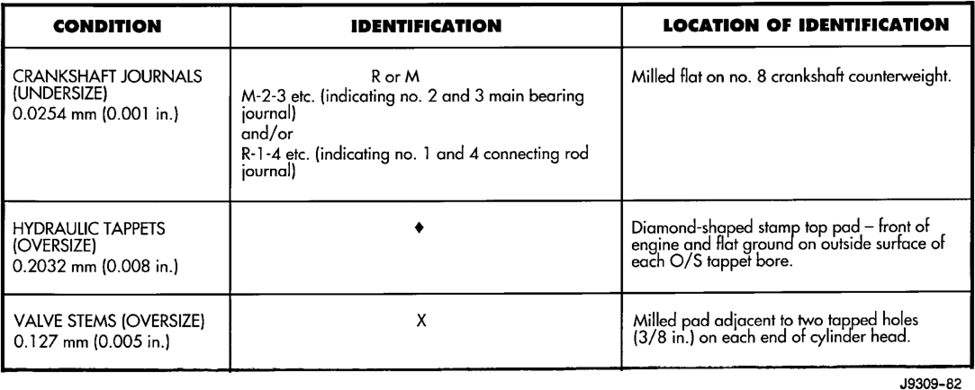
CRANKSHAFT JOURNALS RorM Milled flat on no. 8 crankshaft counterweight.
(UNDERSIZE) M-2-3 etc. {indicating no. 2 and 3 main bearing
0.0254 mm (0.001 in.} journal)
and/or
R-1-4 etc. (indicating no. 1 and 4 connecting rod
journal)
HYDRAULIC TAPPETS Diamond-shaped stamp top pad — front of
(OVERSIZE) engine and flat ground on ouiside surface of
0.2032 mm {0.008 in.) each O/S tappet bore.
VALVE STEMS (OVERSIZE) xX Milled pad adjacent to two tapped holes
0.127 mm (0.005 in.) (3/8 in.) on each end of cylinder head.
J9309-82
5.2L TORQUE SPECIFICATIONS
DESCRIPTION TORQUE Camshaft Sprocket
Bolt . . . . . . . . . . . . . . . . . . . . . .68 N·m (50 ft. lbs.) Camshaft Thrust Plate
Bolts . . . . . . . . . . . . . . . . . . . . .24 N·m (18 ft. lbs.) Chain Case Cover
Bolts . . . . . . . . . . . . . . . . . . . . .41 N·m (30 ft. lbs.) Connecting Rod Cap
Bolts . . . . . . . . . . . . . . . . . . . . .61 N·m (45 ft. lbs.) Crankshaft Main Bearing Cap
Bolts . . . . . . . . . . . . . . . . . . . .115 N·m (85 ft. lbs.) Crankshaft Pulley
Bolts . . . . . . . . . . . . . . . . . . . .24 N·m (210 in. lbs.) Cylinder Head Bolts
Step 1 – Initial . . . . . . . . . . . . .68 N·m (50 ft. lbs.) Step 2 – Final . . . . . . . . . . . .143 N·m (105 ft. lbs.) Cylinder Head Cover
Bolts . . . . . . . . . . . . . . . . . . . . .11 N·m (95 in. lbs.) Exhaust Manifold to Cylinder Head
Bolts/Nuts . . . . . . . . . . . . . . . . .34 N·m (25 ft. lbs.) Flywheel
Bolts . . . . . . . . . . . . . . . . . . . . .75 N·m (55 ft. lbs.) Front Engine Mount Bracket to Block
Bolts . . . . . . . . . . . . . . . . . . . . .81 N·m (60 ft. lbs.) Front Engine Mount
Through Bolt/Nut . . . . . . . . . . .68 N·m (50 ft. lbs.) Generator Mounting
Bolts . . . . . . . . . . . . . . . . . . . . .41 N·m (30 ft. lbs.) Intake Manifold
Bolts . . . . . . . . . .Refer to procedure in this section Oil Pan
Bolts . . . . . . . . . . . . . . . . . . . .24 N·m (215 in. lbs.)
DESCRIPTION TORQUE Oil Pan Drain Plug
Plug. . . . . . . . . . . . . . . . . . . . . .34 N·m (25 ft. lbs.) Oil Pump
Bolts . . . . . . . . . . . . . . . . . . . . .41 N·m (30 ft. lbs.) Oil Pump Cover
Bolts . . . . . . . . . . . . . . . . . . . . .11 N·m (95 in. lbs.) Rear Mount Insulator to Support Bracket
Nuts . . . . . . . . . . . . . . . . . . . . .47 N·m (35 ft. lbs.) Rear Mount Insulator to Crossmember
Nut . . . . . . . . . . . . . . . . . . . . . .47 N·m (35 ft. lbs.) Rear Support Bracket to Transmission
Bolts . . . . . . . . . . . . . . . . . . . .102 N·m (75 ft. lbs.) Rocker Arm
Bolts . . . . . . . . . . . . . . . . . . . . .28 N·m (21 ft. lbs.) Spark Plugs
Plugs . . . . . . . . . . . . . . . . . . . . .41 N·m (30 ft. lbs.) Starter Mounting
Bolts . . . . . . . . . . . . . . . . . . . . .68 N·m (50 ft. lbs.) Thermostat Housing
Bolts . . . . . . . . . . . . . . . . . . . .25 N·m (225 in. lbs.) Throttle Body
Bolts . . . . . . . . . . . . . . . . . . . .23 N·m (200 in. lbs.) Torque Converter Drive Plate
Bolts . . . . . . . . . . . . . . . . . . . .31 N·m (270 in. lbs.) Transmission Support Bracket
Bolts . . . . . . . . . . . . . . . . . . . .102 N·m (75 ft. lbs.) Transmission Support Spacer to
Insulator Mounting Plate – (4wd) Nuts. . . . . . . . . . . . . . . . . . . .204 N·m (150 ft. lbs.) Vibration Damper
Bolt . . . . . . . . . . . . . . . . . . . .183 N·m (135 ft. lbs.) Water Pump to Chain Case Cover
Bolt . . . . . . . . . . . . . . . . . . . . . .41 N·m (30 ft. lbs.)
SPECIAL TOOLS
5.2L ENGINE
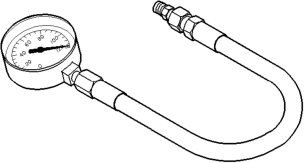

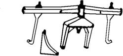

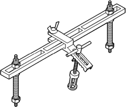

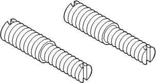

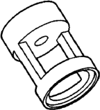

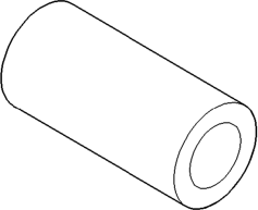

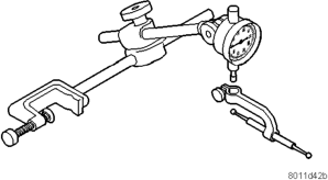

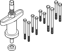

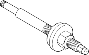

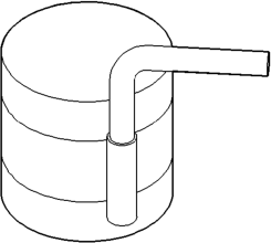

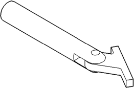

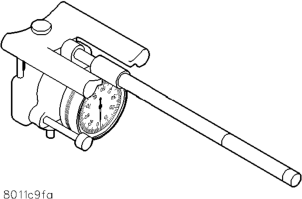


GENERAL INFORMATION
OIL PUMP PRESSURE . . . . . . . . . . . . . . . . . . . . 88 PISTON AND CONNECTING ROD ASSEMBLY . . 88 DESCRIPTION AND OPERATION
ENGINE COMPONENTS . . . . . . . . . . . . . . . . . . 91 ENGINE DESCRIPTION . . . . . . . . . . . . . . . . . . . 88 LUBRICATION SYSTEM . . . . . . . . . . . . . . . . . . . 89 SERVICE PROCEDURES
CRANKSHAFT SERVICE . . . . . . . . . . . . . . . . . . 94 FITTING CONNECTING ROD BEARINGS . . . . . . 93 FITTING CRANKSHAFT MAIN BEARINGS . . . . . 93 FITTING PISTON RINGS . . . . . . . . . . . . . . . . . . 92 FITTING PISTONS . . . . . . . . . . . . . . . . . . . . . . . 92 MEASURING TIMING CHAIN STRETCH . . . . . . . 91 VALVE TIMING . . . . . . . . . . . . . . . . . . . . . . . . . . 91 REMOVAL AND INSTALLATION
CAMSHAFT BEARINGS . . . . . . . . . . . . . . . . . . 102 CAMSHAFT . . . . . . . . . . . . . . . . . . . . . . . . . . . 101 CRANKSHAFT MAIN BEARINGS . . . . . . . . . . . 103 CRANKSHAFT OIL SEAL — FRONT . . . . . . . . . 107 CRANKSHAFT OIL SEALS — REAR . . . . . . . . . 108 CRANKSHAFT . . . . . . . . . . . . . . . . . . . . . . . . . 106 CYLINDER HEAD COVER . . . . . . . . . . . . . . . . . 96 CYLINDER HEAD . . . . . . . . . . . . . . . . . . . . . . . . 97 DISTRIBUTOR DRIVE SHAFT BUSHING . . . . . 103 ENGINE ASSEMBLY . . . . . . . . . . . . . . . . . . . . . . 96 ENGINE CORE OIL AND CAMSHAFT PLUGS . . 109 ENGINE MOUNTS—FRONT . . . . . . . . . . . . . . . . 94 ENGINE MOUNTS—REAR . . . . . . . . . . . . . . . . . 95
GENERAL INFORMATION
OIL PUMP PRESSURE
The MINIMUM oil pump pressure is 41.4 kPa (6 psi) at curb idle. The MAXIMUM oil pump pressure is 207-552 kPa (30-80 psi) at 3,000 RPM or more.
CAUTION: If oil pressure is ZERO at curb idle, DO NOT run engine.
PISTON AND CONNECTING ROD ASSEMBLY
The pistons are elliptically turned so that the diameter at the pin boss is less than its diameter across the thrust face. This allows for expansion under normal operating conditions. Under operating temperatures, expansion forces the pin bosses away from each other, causing the piston to assume a more nearly round shape.
5.9L ENGINE
INDEX
page page
HYDRAULIC TAPPETS . . . . . . . . . . . . . . . . . . . . 99 OIL PAN . . . . . . . . . . . . . . . . . . . . . . . . . . . . . . 104 OIL PUMP . . . . . . . . . . . . . . . . . . . . . . . . . . . . 106 PISTON AND CONNECTING ROD ASSEMBLY . 105 ROCKER ARMS AND PUSH RODS . . . . . . . . . . 97 TIMING CHAIN COVER . . . . . . . . . . . . . . . . . . 100 TIMING CHAIN . . . . . . . . . . . . . . . . . . . . . . . . . 101 VALVE SPRING AND STEM SEAL
REPLACEMENT-IN VEHICLE . . . . . . . . . . . . . 97 VALVES AND VALVE SPRINGS . . . . . . . . . . . . . 98 VIBRATION DAMPER . . . . . . . . . . . . . . . . . . . . . 99 DISASSEMBLY AND ASSEMBLY
CYLINDER BLOCK . . . . . . . . . . . . . . . . . . . . . . 112 HYDRAULIC TAPPETS . . . . . . . . . . . . . . . . . . . 110 OIL PUMP . . . . . . . . . . . . . . . . . . . . . . . . . . . . 112 VALVE SERVICE . . . . . . . . . . . . . . . . . . . . . . . . 110 CLEANING AND INSPECTION
CRANKSHAFT JOURNALS . . . . . . . . . . . . . . . . 113 CYLINDER BLOCK . . . . . . . . . . . . . . . . . . . . . . 115 CYLINDER HEADS . . . . . . . . . . . . . . . . . . . . . . 113 OIL PAN . . . . . . . . . . . . . . . . . . . . . . . . . . . . . . 113 OIL PUMP . . . . . . . . . . . . . . . . . . . . . . . . . . . . 114 PISTON AND CONNECTING ROD ASSEMBLY . 113 SPECIFICATIONS
5.9L ENGINE SPECIFICATIONS . . . . . . . . . . . . 116 5.9L TORQUE SPECIFICATIONS . . . . . . . . . . . 118 SPECIAL TOOLS
5.9L ENGINE . . . . . . . . . . . . . . . . . . . . . . . . . . 119
All pistons are machined to the same weight, regardless of size, to maintain piston balance.
The piston pin rotates in the piston only and is retained by the press interference fit of the piston pin in the connecting rod.
DESCRIPTION AND OPERATION
ENGINE DESCRIPTION
The 5.9 Liter (360 CID) eight-cylinder engine is a V-Type lightweight, single cam, overhead valve engine with hydraulic roller tappets.
This engine is designed for unleaded fuel. Engine lubrication system consists of a rotor type oil pump and a full flow oil filter.
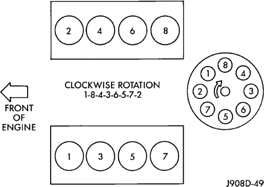
The cylinders are numbered from front to rear; 1, 3, 5, 7 on the left bank and 2, 4, 6, 8 on the right bank. The firing order is 1-8-4-3-6-5-7-2 (Fig. 1).
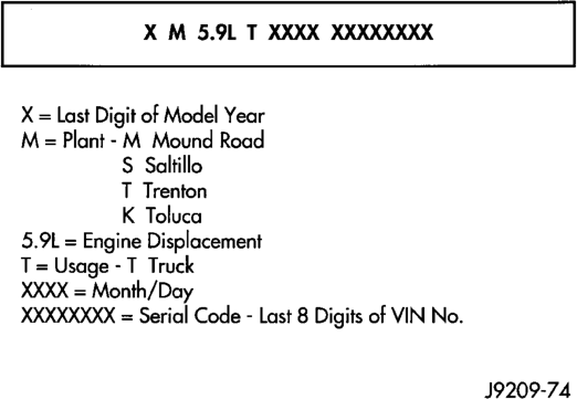
The engine serial number is stamped into a machined pad located on the left, front corner of the cylinder block. When component part replacement is necessary, use the engine type and serial number for reference (Fig. 2).
LUBRICATION SYSTEM
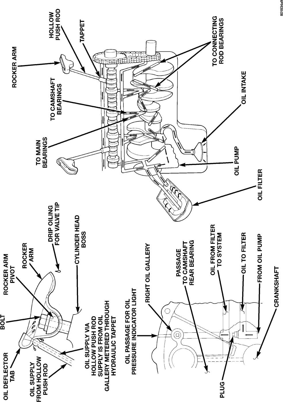
A gear—type positive displacement pump is mounted at the underside of the rear main bearing cap. The pump draws oil through the screen and inlet tube from the sump at the rear of the oil pan. The oil is driven between the drive and idler gears and pump body, then forced through the outlet to the block. An oil gallery in the block channels the oil to the inlet side of the full flow oil filter. After passing through the filter element, the oil passes from the center outlet of the filter through an oil gallery that channels the oil up to the main gallery which extends the entire length on the right side of the block. The oil then goes down to the No. 1 main bearing, back up to the left side of the block and into the oil gallery on the left side of the engine.
Galleries extend downward from the main oil gallery to the upper shell of each main bearing. The crankshaft is drilled internally to pass oil from the main bearing journals to the connecting rod journals. Each connecting rod bearing has half a hole in it, oil passes through the hole when the rods rotate and the hole lines up, oil is then thrown off as the rod rotates. This oil throw off lubricates the camshaft lobes, distributor drive gear, cylinder walls, and piston pins.
The hydraulic valve tappets receive oil directly from the main oil gallery. The camshaft bearings receive oil from the main bearing galleries. The front camshaft bearing journal passes oil through the camshaft sprocket to the timing chain. Oil drains back to the oil pan under the number one main bearing cap.
The oil supply for the rocker arms and bridged pivot assemblies is provided by the hydraulic valve tappets which pass oil through hollow push rods to a hole in the corresponding rocker arm. Oil from the rocker arm lubricates the valve train components. The oil then passes down through the push rod guide holes, and the oil drain back passages in the cylinder head past the valve tappet area, and returns to the oil pan.

ENGINE COMPONENTS
CYLINDER HEADS
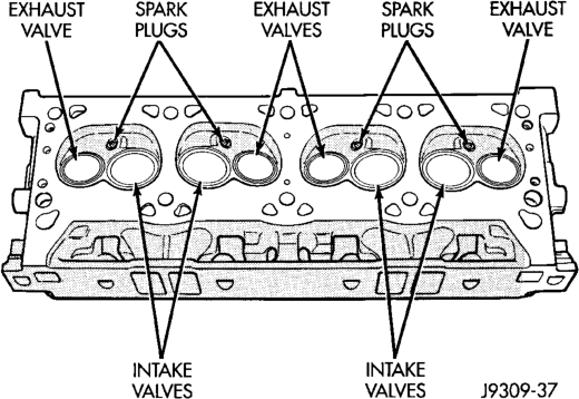
The alloy cast iron cylinder heads (Fig. 4) are held in place by 10 bolts. The spark plugs are located in the peak of the wedge between the valves.
The 5.9L cylinder head is identified by the foundry mark CF.
PISTONS
The pistons are elliptically turned so that the diameter at the pin boss is less than its diameter across the thrust face. This allows for expansion under normal operating conditions. Under operating temperatures, expansion forces the pin bosses away from each other, causing the piston to assume a more nearly round shape.
All pistons are machined to the same weight, regardless of size, to maintain piston balance.
The piston pin rotates in the piston only and is retained by the press interference fit of the piston pin in the connecting rod.
VALVES AND VALVE SPRINGS
The valves are arranged in-line and inclined 18°. The rocker pivot support and the valve guides are cast integral with the heads.
SERVICE PROCEDURES
VALVE TIMING
(1) Turn crankshaft until the No.6 exhaust valve is closing and No.6 intake valve is opening.
(2) Insert a 6.350 mm (1/4 inch) spacer between rocker arm pad and stem tip of No.1 intake valve. Allow spring load to bleed tappet down giving in effect a solid tappet.
(3) Install a dial indicator so plunger contacts valve spring retainer as nearly perpendicular as possible. Zero the indicator.
(4) Rotate the crankshaft clockwise (normal running direction) until the valve has lifted 0.863 mm (0.034 inch). The timing of the crankshaft should now read from 10° before top dead center to 2° after top dead center. Remove spacer.
CAUTION: DO NOT turn crankshaft any further clockwise as valve spring might bottom and result in serious damage.
If reading is not within specified limits: • Check sprocket index marks. • Inspect timing chain for wear. • Check accuracy of DC mark on timing indicator.
MEASURING TIMING CHAIN STRETCH
NOTE: To access timing chain Refer to Timing Chain Cover in Removal and Installation Section.
(1) Place a scale next to the timing chain so that any movement of the chain may be measured.
(2) Place a torque wrench and socket over camshaft sprocket attaching bolt. Apply torque in the direction of crankshaft rotation to take up slack; 41 N·m (30 ft. lbs.) torque with cylinder head installed or 20 N·m (15 ft. lbs.) torque with cylinder head removed. With a torque applied to the camshaft sprocket bolt, crankshaft should not be permitted to move. It may be necessary to block the crankshaft to prevent rotation.
(3) Hold a scale with dimensional reading even with the edge of a chain link. With cylinder heads installed, apply 14 N·m (30 ft. lbs.) torque in the reverse direction. With the cylinder heads removed, apply 20 N·m (15 ft. lbs.) torque in the reverse direction. Note the amount of chain movement (Fig. 5).
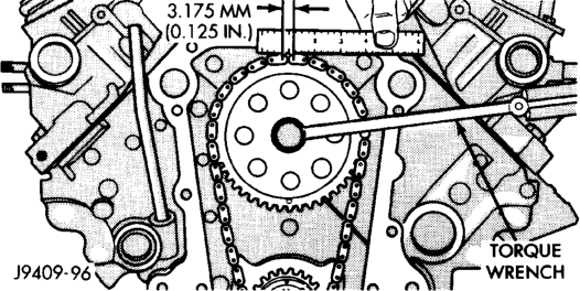
(4) Install a new timing chain, if its movement exceeds 3.175 mm (1/8 inch).
(5) If chain is not satisfactory, remove camshaft sprocket attaching bolt and remove timing chain with crankshaft and camshaft sprockets.
(6) Place both camshaft sprocket and crankshaft sprocket on the bench with timing marks on exact imaginary center line through both camshaft and crankshaft bores.
(7) Place timing chain around both sprockets. (8) Turn crankshaft and camshaft to line up with keyway location in crankshaft sprocket and in camshaft sprocket.
(9) Lift sprockets and chain (keep sprockets tight against the chain in position as described).
(10) Slide both sprockets evenly over their respective shafts and use a straightedge to check alignment of timing marks (Fig. 6).
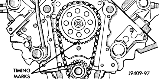
(11) Install the camshaft bolt. Tighten the bolt to 47 N·m (35 ft. lbs.) torque.
(12) Check camshaft end play. The end play should be 0.051-0.152 mm (0.002-0.006 inch) with a new thrust plate and up to 0.254 mm (0.010 inch) with a used thrust plate. If not within these limits install a new thrust plate.
FITTING PISTONS
Piston and cylinder wall must be clean and dry. Specified clearance between the piston and the cylinder wall is 0.013-0.038 mm (0.0005-0.0015 inch) at 21°C (70°F).
Piston diameter should be measured at the top of skirt, 90° to piston pin axis. Cylinder bores should be measured halfway down the cylinder bore and transverse to the engine crankshaft center line.
Pistons and cylinder bores should be measured at normal room temperature, 21°C (70°F).
Check the pistons for taper and elliptical shape before they are fitted into the cylinder bore (Fig. 7).
FITTING PISTON RINGS
(1) Measurement of end gaps:
(a) Measure piston ring gap 2 inches from bottom of cylinder bore. An inverted piston can be used to push the rings down to ensure positioning rings squarely in the cylinder bore before measuring. (b) Insert feeler gauge in the gap. The top compression ring gap should be between 0.254-0.508 mm (0.010-0.020 inch). The second compression
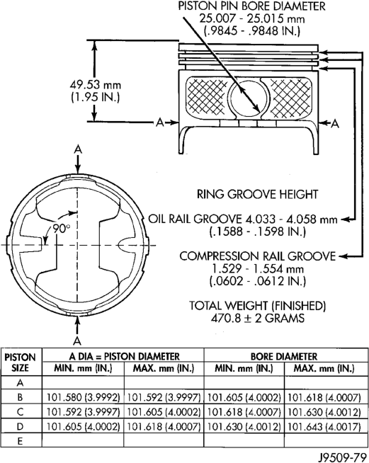
ring gap should be between 0.508-0.762 mm (0.020- 0.030 inch). The oil ring gap should be 0.254-1.270 mm (0.010-0.050 inch).
(c) Rings with insufficient end gap may be properly filed to the correct dimension. Rings with excess gaps should not be used. (2) Install rings and confirm ring side clearance:
(a) Install oil rings being careful not to nick or scratch the piston. Install the oil control rings according to instructions in the package. It is not necessary to use a tool to install the upper and lower rails. Insert oil rail spacer first, then side rails.
(b) Install the second compression rings using Installation Tool C-4184. The compression rings must be installed with the identification mark face up (toward top of piston) and chamfer facing down. An identification mark on the ring is a drill point, a stamped letter “O”, an oval depression or the word TOP (Fig. 8) (Fig. 10).
(c) Using a ring installer, install the top compression ring with the chamfer facing up (Fig. 9) (Fig. 10). An identification mark on the ring is a drill point, a stamped letter “O”, an oval depression or the word TOP facing up.
(d) Measure side clearance between piston ring and ring land. Clearance should be 0.074-0.097 mm
(0.0029-0.0038 inch) for the compression rings. The steel rail oil ring should be free in groove, but should not exceed 0.246 mm (0.0097 inch) side clearance.
(e) Pistons with insufficient or excessive side clearance should be replaced.
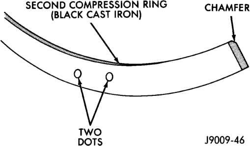
(Typical)
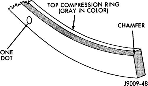
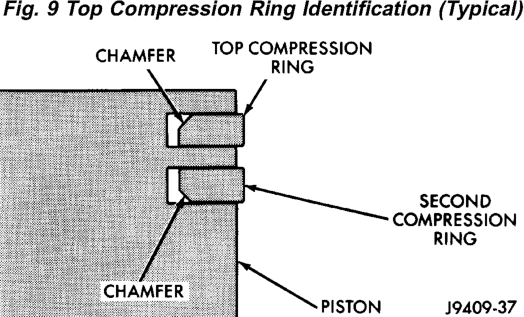
(Typical)
FITTING CONNECTING ROD BEARINGS
Fit all rods on a bank until completed. DO NOT alternate from one bank to another, because connecting rods and pistons are not interchangeable from one bank to another.
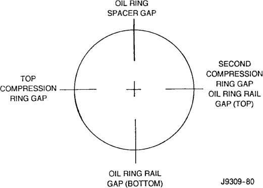
The bearing caps are not interchangeable and should be marked at removal to ensure correct assembly.
Each bearing cap has a small V-groove across the parting face. When installing the lower bearing shell, make certain that the V-groove in the shell is in line with the V-groove in the cap. This provides lubrication of the cylinder wall in the opposite bank.
The bearing shells must be installed so that the tangs are in the machined grooves in the rods and caps.
Limits of taper or out-of-round on any crankshaft journals should be held to 0.025 mm (0.001 inch). Bearings are available in 0.025 mm (0.001 inch), 0.051 mm (0.002 inch), 0.076 mm (0.003 inch), 0.254 mm (0.010 inch) and 0.305 mm (0.012 inch) undersize. Install the bearings in pairs. DO NOT use a new bearing half with an old bearing half. DO NOT file the rods or bearing caps.
FITTING CRANKSHAFT MAIN BEARINGS
Bearing caps are not interchangeable and should be marked at removal to ensure correct assembly. Upper and lower bearing halves are NOT interchangeable. Lower main bearing halves of No.2 and 4 are interchangeable.
Upper and lower No.3 bearing halves are flanged to carry the crankshaft thrust loads. They are NOT interchangeable with any other bearing halves in the engine (Fig. 12). Bearing shells are available in standard and the following undersizes: 0.25 mm (0.001 inch), 0.051 mm (0.002 inch), 0.076 mm (0.003 inch), 0.254 mm (0.010 inch) and 0.305 mm (0.012 inch). Never install an undersize bearing that will reduce clearance below specifications.
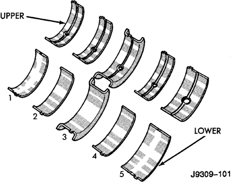
CRANKSHAFT SERVICE
A crankshaft which has undersize journals will be stamped with 1/4 inch letters on the milled flat on the No.3 crankshaft counterweight (Fig. 13).
FOR EXAMPLE: R2 stamped on the No.3 crankshaft counterweight indicates that the No.2 rod journal is 0.025 mm (0.001 in) undersize. M4 indicates that the No.4 main journal is 0.025 mm (0.001 in) undersize. R3 M2 indicates that the No.3 rod journal and the No.2 main journal are 0.025 mm (0.001 in) undersize.
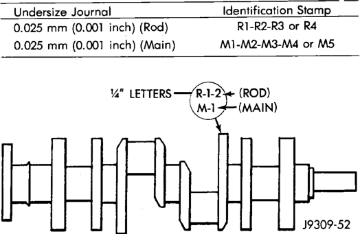
When a crankshaft is replaced, all main and connecting rod bearings should be replaced with new bearings. Therefore, selective fitting of the bearings is not required when a crankshaft and bearings are replaced.
INSPECTION OF JOURNALS
The crankshaft connecting rod and main journals should be checked for excessive wear, taper and scoring. The maximum taper or out-of-round on any crankshaft journal is 0.025 mm (0.001 inch).
Journal grinding should not exceed 0.305 mm (0.012 inch) under the standard journal diameter. DO NOT grind thrust faces of No.3 main bearing. DO NOT nick crank pin or bearing fillets. After grinding, remove rough edges from crankshaft oil holes and clean out all oil passages.
CAUTION: After any journal grind, it is important that the final paper or cloth polish be in the same direction as the engine rotates.
REMOVAL AND INSTALLATION
ENGINE MOUNTS—FRONT
REMOVAL
(1) Disconnect the negative cable from the battery. (2) Position fan to assure clearance for radiator top tank and hose.
CAUTION: DO NOT lift the engine by the intake manifold.
(3) Install engine lifting fixture. (4) Raise vehicle on hoist. (5) Remove the engine support insulator thru-bolts and nuts (Fig. 14) (Fig. 15).
(6) Raise engine SLIGHTLY. Remove the engine support insulator bolts. Remove the engine support insulator assembly.
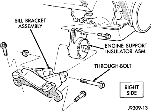
(7) If required, remove the sill bracket assembly.
INSTALLATION
(1) If the sill bracket assembly was removed, install the bracket to the sill assembly.
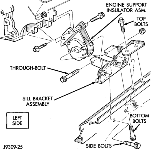
(a) RIGHT SIDE—Install the sill bracket assembly onto the sill assembly (Fig. 14). Install and tighten the bolts to 65 N·m (48 ft. lbs.) torque.
(b) LEFT SIDE—Install the sill bracket assembly onto the sill assembly (Fig. 15). Install and tighten the 2 top bolts to 65 N·m (48 ft. lbs.) torque. Install and tighten the 2 side bolts to 95 N·m (70 ft. lbs.) torque. Install and tighten the 2 bottom bolts to 121 N·m (89 ft. lbs.) torque. (2) With the engine raised SLIGHTLY, position engine support insulator assembly onto the engine block (Fig. 14) (Fig. 15). Install bolts and tighten to 88 N·m (65 ft. lbs.) torque.
(3) Lower engine with lifting fixture while aligning engine support insulator assembly into sill bracket assembly.
(4) Install the thru-bolt and nut. Tighten the RIGHT SIDE nut to 81 N·m (60 ft. lbs.) torque. Tighten the LEFT SIDE nut to 81 N·m (60 ft. lbs.) torque.
(5) Lower the vehicle. (6) Remove lifting fixture. (7) Connect the negative cable to the battery.
ENGINE MOUNTS—REAR
REMOVAL
(1) Disconnect the negative cable from the battery. (2) Raise the vehicle and support the transmission. (3) Remove the bolts holding the mount assy. to the crossmember.
(4) Raise the transmission and engine SLIGHTLY.
(5) Remove engine mount bracket thru-bolt and nut (Fig. 16).
(6) Remove the rear mount assy. (7) If necessary, remove the bolts holding the rear mount bracket to the transmission. Remove the bracket from the exhaust pipe hanger. Remove the bracket.
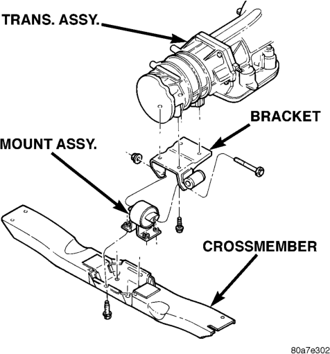
INSTALLATION
(1) Position the rear mount bracket onto the exhaust hanger (if previously removed). Position the rear mount bracket assembly onto the transmission and install the bolts. Tighten the bolts to 46 N·m (34 ft. lbs.).
(2) Position the mount into the mount bracket and install the thru-bolt and nut. DO NOT tighten the bolt at this time.
(3) Install the engine mount bracket assembly to the adaptor. Install the bolts and tighten to 75 N·m (55 ft. lbs.) torque.
(4) Lower the transmission until the mount fastening studs are in position in the crossmember. (5) Remove the transmission support. (6) Install the mount fastening nuts and tighten the nuts to 54 N·m (40 ft. lbs.) torque.
(7) Tighten the thru-bolt nut to 65 N·m (48 ft. lbs.) torque.
(8) Lower the vehicle. (9) Connect the negative cable to the battery.
ENGINE ASSEMBLY
REMOVAL
(1) Scribe hood hinge outlines on hood and remove the hood.
(2) Remove the battery. (3) Drain cooling system. (4) Remove the air cleaner and tube. (5) Set fan shroud aside. (6) Remove radiator and heater hoses. Remove the radiator (refer to Group 7, Cooling System).
(7) Remove the vacuum lines. (8) Remove the distributor cap and wiring. (9) Disconnect the accelerator linkage. (10) Perform the Fuel System Pressure Release procedure. Refer to Group 14, Fuel Systems for the correct procedure.
(11) Disconnect the fuel supply line from the injector rail. Refer to Group 14, Fuel Systems for the correct procedure.
(12) Remove throttle body. (13) Remove the starter wires. (14) Remove the oil pressure wire. (15) Discharge the air conditioning system, if equipped (refer to Group 24, Heating and Air Conditioning for service procedures).
(16) Remove air conditioning hoses. (17) Disconnect the power steering hoses, if equipped.
(18) Remove starter motor (refer to Group 8B, Battery/Starter Service).
(19) Remove the generator (refer to Group 8C, Generator Service).
(20) Raise and support the vehicle on a hoist. (21) Disconnect exhaust pipe at manifold. (22) Support automatic transmission with a transmission stand. This will assure that the torque converter will remain in proper position in the transmission housing.
(23) Remove bell housing bolts and inspection plate. Attach C-clamp on front bottom of transmission torque converter housing to prevent torque converter from coming out.
(24) Remove torque converter drive plate bolts from torque converter drive plate. Mark converter and drive plate to aid in assembly.
(25) Disconnect the engine from the torque converter drive plate.
CAUTION: DO NOT lift the engine by the intake manifold.
(26) Install an engine lifting fixture. (27) Remove the engine front mount thru-bolts. (28) Lower the vehicle. (29) Remove engine from engine compartment. (30) Install on engine repair stand.
INSTALLATION
(1) Remove engine from the repair stand and position in the engine compartment.
(2) Install engine support fixture. (3) Raise and support the vehicle on a hoist. (4) Position the torque converter and drive plate. Install torque converter drive plate bolts. Tighten the bolts to 31 N·m (270 in. lbs.) torque.
(5) Install the engine front mount thru-bolts. (6) Install bell housing bolts. Tighten the bolts to 41 N·m (30 ft. lbs.) torque.
(7) Remove C-clamp and install inspection plate. (8) Remove stand from transmission. (9) Install exhaust pipe to manifold. (10) Lower the vehicle. (11) Remove engine lifting fixture. (12) Install the generator (refer to Group 8C, Generator Service).
(13) Install starter motor (refer to Group 8B, Battery/Starter Service).
(14) Install power steering hoses, if equipped. (15) Install air conditioning hoses. (16) Charge the air conditioner, if equipped (refer to Group 24, Heater and Air Conditioning for service procedures).
(17) Using a new gasket, install throttle body. Tighten the throttle body bolts to 23 N·m (200 in. lbs.) torque.
(18) Connect the accelerator linkage. (19) Connect the starter wires. (20) Connect the oil pressure wire. (21) Install the distributor cap and wiring. (22) Install vacuum lines. (23) Install radiator, radiator hoses and heater hoses (refer to Group 7, Cooling System).
(24) Install fan shroud in position. (25) Install the battery (26) Fill cooling system (refer to Group 7, Cooling System for the proper procedure).
(27) Install the air cleaner. (28) Warm engine and adjust. (29) Install hood and line up. (30) Road test vehicle.
CYLINDER HEAD COVER
A steel backed silicon gasket is used with the cylinder head cover (Fig. 17). This gasket can be used again.
REMOVAL
(1) Disconnect the negative cable from the battery. (2) Disconnect closed ventilation system and evaporation control system from cylinder head cover.
(3) Remove cylinder head cover and gasket. The gasket may be used again.
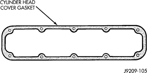
INSTALLATION
(1) Clean cylinder head cover gasket surface. (2) Clean head rail, if necessary. (3) Inspect cover for distortion and straighten, if necessary.
(4) Check the gasket for use in head cover installation. If damaged, use a new gasket.
(5) Position the cylinder head cover onto the gasket. Tighten the bolts to 11 N·m (95 in. lbs.) torque.
(6) Install closed crankcase ventilation system and evaporation control system.
(7) Connect the negative cable to the battery.
ROCKER ARMS AND PUSH RODS
REMOVAL
(1) Disconnect spark plug wires by pulling on the boot straight out in line with plug.
(2) Remove cylinder head cover and gasket. (3) Remove the rocker arm bolts and pivots (Fig. 18). Place them on a bench in the same order as removed.
(4) Remove the push rods and place them on a bench in the same order as removed.
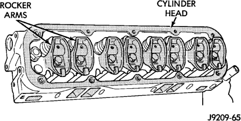
INSTALLATION
(1) Rotate the crankshaft until the “V8” mark lines up with the TDC mark on the timing chain case cover. This mark is located 147° ATDC from the No.1 firing position.
(2) Install the push rods in the same order as removed.
(3) Install rocker arm and pivot assemblies in the same order as removed. Tighten the rocker arm bolts to 28 N·m (21 ft. lbs.) torque.
CAUTION: DO NOT rotate or crank the engine during or immediately after rocker arm installation. Allow the hydraulic roller tappets adequate time to bleed down (about 5 minutes).
(4) Install cylinder head cover. (5) Connect spark plug wires.
VALVE SPRING AND STEM SEAL REPLACEMENT- IN VEHICLE
(1) Set engine basic timing to Top Dead Center (TDC).
(2) Remove the air cleaner. (3) Remove cylinder head covers and spark plugs. (4) Remove coil wire from distributor and secure to good ground to prevent engine from starting.
(5) Using suitable socket and flex handle at crankshaft retaining bolt, turn engine so the No.1 piston is at TDC on the compression stroke.
(6) Remove rocker arms. (7) With air hose attached to an adapter installed in No.1 spark plug hole, apply 620-689 kPa (90-100 psi) air pressure.
(8) Using Valve Spring Compressor Tool MD-998772A with adaptor 6716A, compress valve spring and remove retainer valve locks and valve spring.
(9) Install seals on the exhaust valve stem and position down against valve guides.
(10) The intake valve stem seals should be pushed firmly and squarely over the valve guide using the valve stem as a guide. DO NOT force seal against top of guide. When installing the valve retainer locks, compress the spring only enough to install the locks.
(11) Follow the same procedure on the remaining 7 cylinders using the firing sequence 1-8-4-3-6-5-7-2. Make sure piston in cylinder is at TDC on the valve spring that is being removed.
(12) Remove adapter from the No.1 spark plug hole.
(13) Install rocker arms. (14) Install covers and coil wire to distributor. (15) Install air cleaner. (16) Road test vehicle.
CYLINDER HEAD
REMOVAL
(1) Disconnect the battery negative cable. (2) Drain cooling system (refer to Group 7, Cooling System for the proper procedures).
(3) Remove the generator. (4) Remove closed crankcase ventilation system.
(5) Disconnect the evaporation control system. (6) Remove the air cleaner. (7) Perform the Fuel System Pressure Release procedure (refer to Group 14, Fuel System). Disconnect the fuel supply line.
(8) Disconnect accelerator linkage and if so equipped, the speed control and transmission kickdown cables.
(9) Remove distributor cap and wires. (10) Disconnect the coil wires. (11) Disconnect heat indicator sending unit wire. (12) Disconnect heater hoses and bypass hose. (13) Remove cylinder head covers and gaskets. (14) Remove intake manifold and throttle body as an assembly. Discard the flange side gaskets and the front and rear cross-over gaskets.
(15) Remove exhaust manifolds. (16) Remove rocker arm assemblies and push rods. Identify to ensure installation in original locations.
(17) Remove the head bolts from each cylinder head and remove cylinder heads. Discard the cylinder head gasket.
(18) Remove spark plugs.
INSTALLATION
(1) Position the new cylinder head gaskets onto the cylinder block.
(2) Position the cylinder heads onto head gaskets and cylinder block.
(3) Starting at top center, tighten all cylinder head bolts, in sequence, to 68 N·m (50 ft. lbs.) torque (Fig. 19). Repeat procedure, tighten all cylinder head bolts to 143 N·m (105 ft. lbs.) torque. Repeat procedure to confirm that all bolts are at 143 N·m (105 ft. lbs.) torque.
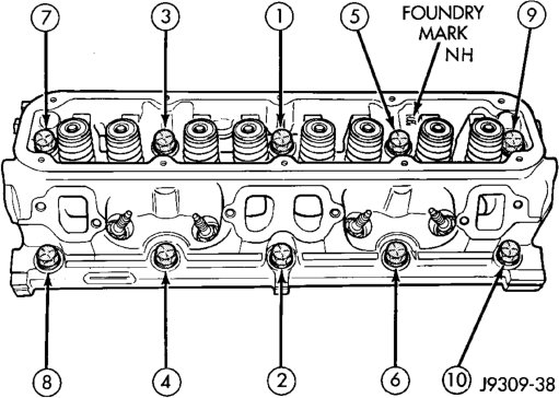
CAUTION: When tightening the rocker arm bolts, make sure the piston in that cylinder is NOT at TDC. Contact between the valves and piston could occur.
(4) Install push rods and rocker arm assemblies in their original position. Tighten the bolts to 28 N·m (21 ft. lbs.) torque.
(5) Install the intake manifold and throttle body assembly (refer to Group 11, Exhaust System and Intake Manifold).
(6) Install exhaust manifolds. Tighten the bolts and nuts to 34 N·m (25 ft. lbs.) torque.
(7) Adjust spark plugs to specifications (refer to Group 8D, Ignition System). Install the plugs and tighten to 41 N·m (30 ft. lbs.) torque.
(8) Install coil wires. (9) Connect heat indicator sending unit wire. (10) Connect the heater hoses and bypass hose. (11) Install distributor cap and wires. (12) Connect the accelerator linkage and if so equipped, the speed control and transmission kickdown cables.
(13) Install the fuel supply line. (14) Install the generator and drive belt. Tighten generator mounting bolt to 41 N·m (30 ft. lbs.) torque. Tighten the adjusting strap bolt to 23 N·m (200 in. lbs.) torque. Refer to Group 7, Cooling System for adjusting the belt tension.
(15) Install the intake manifold-to-generator bracket support rod. Tighten the bolts.
(16) Place the cylinder head cover gaskets in position and install cylinder head covers. Tighten the bolts to 11 N·m (95 in. lbs.) torque.
(17) Install closed crankcase ventilation system. (18) Connect the evaporation control system. (19) Install the air cleaner. (20) Fill cooling system (refer to Group 7, Cooling System for proper procedure).
(21) Connect the negative cable to the battery.
VALVES AND VALVE SPRINGS
REMOVAL
(1) Remove the cylinder head. (2) Compress valve springs using Valve Spring Compressor Tool MD- 998772A and adapter 6716A.
(3) Remove valve retaining locks, valve spring retainers, valve stem seals and valve springs.
(4) Before removing valves, remove any burrs from valve stem lock grooves to prevent damage to the valve guides. Identify valves to ensure installation in original location.
INSTALLATION
(1) Clean valves thoroughly. Discard burned, warped and cracked valves.
(2) Remove carbon and varnish deposits from inside of valve guides with a reliable guide cleaner. (3) Measure valve stems for wear. If wear exceeds 0.051 mm (0.002 inch), replace the valve.
(4) Coat valve stems with lubrication oil and insert them in cylinder head.
(5) If valves or seats are reground, check valve stem height. If valve is too long, replace cylinder head.
(6) Install new seals on all valve guides. Install valve springs and valve retainers.
(7) Compress valve springs with Valve Spring Compressor Tool MD-998772A and adapter 6716A, install locks and release tool. If valves and/or seats are ground, measure the installed height of springs. Make sure the measurement is taken from bottom of spring seat in cylinder head to the bottom surface of spring retainer. If spacers are installed, measure from the top of spacer. If height is greater than 42.86 mm (1-11/16 inches), install a 1.587 mm (1/16 inch) spacer in head counterbore. This should bring spring height back to normal 41.27 to 42.86 mm (1-5/8 to 1-11/16 inch).
HYDRAULIC TAPPETS
REMOVAL
(1) Remove the air cleaner. (2) Remove cylinder head cover, rocker assembly and push rods. Identify push rods to ensure installation in original location.
(3) Remove intake manifold, yoke retainer and aligning yokes.
(4) Slide Hydraulic Tappet Remover/Installer Tool C-4129-A through opening in cylinder head and seat tool firmly in the head of tappet.
(5) Pull tappet out of bore with a twisting motion. If all tappets are to be removed, identify tappets to ensure installation in original location.
INSTALLATION
(1) If the tappet or bore in cylinder block is scored, scuffed, or shows signs of sticking, ream the bore to next oversize. Replace with oversize tappet.
(2) Lubricate tappets. (3) Install tappets and push rods in their original positions. Ensure that the oil feed hole in the side of the tappet body faces up (away from the crankshaft).
(4) Install aligning yokes with ARROW toward camshaft.
(5) Install yoke retainer. Tighten the bolts to 23 N·m (200 in. lbs.) torque. Install intake manifold.
(6) Install push rods in original positions. (7) Install rocker arm. (8) Install cylinder head cover. (9) Start and operate engine. Warm up to normal operating temperature.
CAUTION: To prevent damage to valve mechanism, engine must not be run above fast idle until all hydraulic tappets have filled with oil and have become quiet.
VIBRATION DAMPER
REMOVAL
(1) Disconnect the negative cable from the battery. (2) Remove fan shroud retainer bolts and set shroud back over engine.
(3) Remove the cooling system fan. (4) Remove the serpentine belt (refer to Group 7, Cooling System).
(5) Remove the vibration damper pulley. (6) Remove vibration damper bolt and washer from end of crankshaft.
(7) Install bar and screw from Puller Tool Set C-3688. Install 2 bolts with washers through the puller tool and into the vibration damper (Fig. 20).
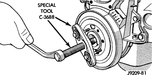
(8) Pull vibration damper off of the crankshaft.
INSTALLATION
(1) Position the vibration damper onto the crankshaft.
(2) Place installing tool, part of Puller Tool Set C-3688 in position and press the vibration damper onto the crankshaft (Fig. 21).
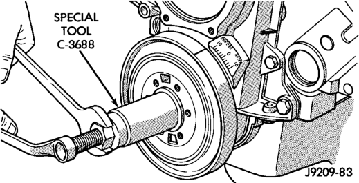
(3) Install the crankshaft bolt and washer. Tighten the bolt to 183 N·m (135 ft. lbs.) torque.
(4) Install the crankshaft pulley. Tighten the pulley bolts to 23 N·m (200 in. lbs.) torque.
(5) Install the serpentine belt (refer to Group 7, Cooling System).
(6) Install the cooling system fan. Tighten the bolts to 23 N·m (17 ft. lbs.) torque.
(7) Position the fan shroud and install the bolts. Tighten the retainer bolts to 11 N·m (95 in. lbs.) torque.
(8) Connect the negative cable to the battery.
TIMING CHAIN COVER
REMOVAL
(1) Disconnect the negative cable from the battery. (2) Drain cooling system (refer to Group 7, Cooling System).
(3) Remove the serpentine belt (refer to Group 7, Cooling System).
(4) Remove water pump (refer to Group 7, Cooling System).
(5) Remove power steering pump (refer to Group 19, Steering).
(6) Remove vibration damper. (7) Loosen oil pan bolts and remove the front bolt at each side.
(8) Remove the cover bolts. (9) Remove chain case cover and gasket using extreme caution to avoid damaging oil pan gasket.
(10) Place a suitable tool behind the lips of the oil seal to pry the oil seal outward. Be careful not to damage the crankshaft seal surface of cover (Fig. 22).
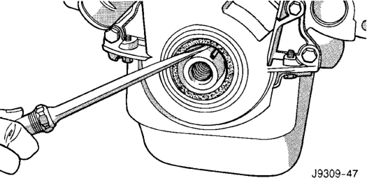
INSTALLATION
(1) Using a new cover gasket, carefully install chain case cover to avoid damaging oil pan gasket. Use a small amount of Mopart Silicone Rubber Adhesive Sealant, or equivalent, at the joint between timing chain cover gasket and the oil pan gasket. Finger tighten the timing chain cover bolts at this time.
(2) Place the smaller diameter of the oil seal over Front Oil Seal Installation Tool 6635 (Fig. 23). Seat the oil seal in the groove of the tool.
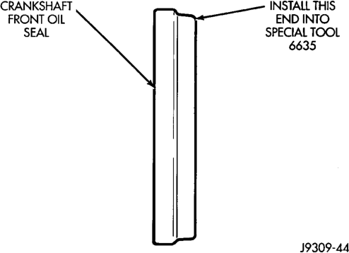
(3) Position the seal and tool onto the crankshaft (Fig. 24).
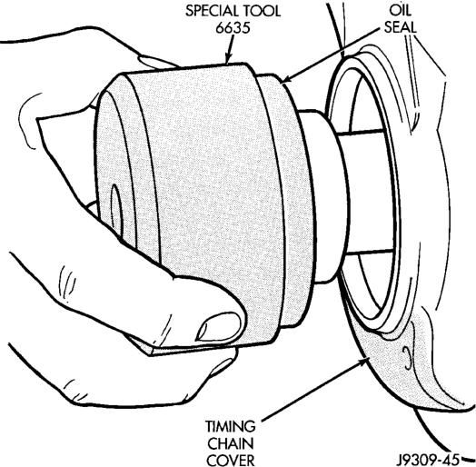
(4) Tighten the 4 lower chain case cover bolts to 13N·m (10 ft.lbs.) to prevent the cover from tipping during seal installation.
(5) Using the vibration damper bolt, tighten the bolt to draw the seal into position on the crankshaft (Fig. 25).
(6) Loosen the 4 bolts tightened in step 4 to allow realignment of front cover assembly.
(7) Tighten chain case cover bolts to 41 N·m (30 ft. lbs.) torque. Tighten oil pan bolts to 24 N·m (215 in. lbs.) torque.
(8) Remove the vibration damper bolt and seal installation tool. (9) Install vibration damper.
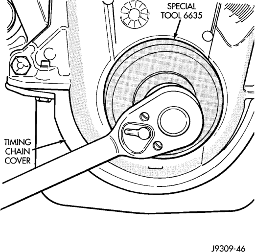
(10) Install water pump and housing assembly using new gaskets (refer to Group 7, Cooling System). Tighten bolts to 41 N·m (30 ft. lbs.) torque.
(11) Install power steering pump (refer to Group 19, Steering).
(12) Install the serpentine belt (refer to Group 7, Cooling System).
(13) Install the cooling system fan. Tighten the bolts to 23 N·m (17 ft. lbs.) torque.
(14) Position the fan shroud and install the bolts. Tighten the bolts to 11 N·m (95 in. lbs.) torque.
(15) Fill cooling system (refer to Group 7, Cooling System for the proper procedure).
(16) Connect the negative cable to the battery.
TIMING CHAIN
REMOVAL
(1) Remove Timing Chain Cover Refer to procedure in this section.
(2) Remove camshaft sprocket attaching bolt and remove timing chain with crankshaft and camshaft sprockets.
INSTALLATION
(1) Place both camshaft sprocket and crankshaft sprocket on the bench with timing marks on exact imaginary center line through both camshaft and crankshaft bores.
(2) Place timing chain around both sprockets. (3) Turn crankshaft and camshaft to line up with keyway location in crankshaft sprocket and in camshaft sprocket.
(4) Lift sprockets and chain (keep sprockets tight against the chain in position as described).
(5) Slide both sprockets evenly over their respective shafts and use a straightedge to check alignment of timing marks (Fig. 26).
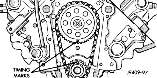
(6) Install the camshaft bolt. Tighten the bolt to 68 N·m (50 ft. lbs.) torque.
(7) Check camshaft end play. The end play should be 0.051-0.152 mm (0.002-0.006 inch) with a new thrust plate and up to 0.254 mm (0.010 inch) with a used thrust plate. If not within these limits install a new thrust plate.
CAMSHAFT
NOTE: The camshaft has an integral oil pump and distributor drive gear (Fig. 27).
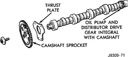
REMOVAL
(1) Remove intake manifold. (2) Remove cylinder head covers. (3) Remove timing case cover and timing chain. (4) Remove rocker arms. (5) Remove push rods and tappets. Identify each part so it can be installed in its original location.
(6) Remove distributor and lift out the oil pump and distributor drive shaft.
(7) Remove camshaft thrust plate, note location of oil tab (Fig. 28).
(8) Install a long bolt into front of camshaft to facilitate removal of the camshaft. Remove camshaft,
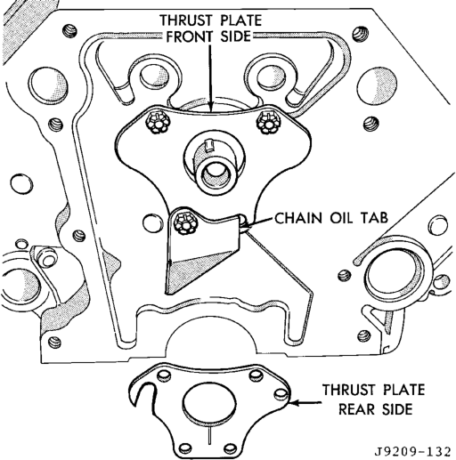
being careful not to damage cam bearings with the cam lobes.
INSTALLATION
(1) Lubricate camshaft lobes and camshaft bearing journals and insert the camshaft to within 51 mm (2 inches) of its final position in cylinder block.
NOTE: Whenever an engine has been rebuilt, a new camshaft and/or new tappets installed, add 1 pint of Mopar Crankcase Conditioner, or equivalent. The oil mixture should be left in engine for a minimum of 805 km (500 miles). Drain at the next normal oil change.
(2) Install Camshaft Gear Installer Tool C-3509 with tongue back of distributor drive gear (Fig. 29).
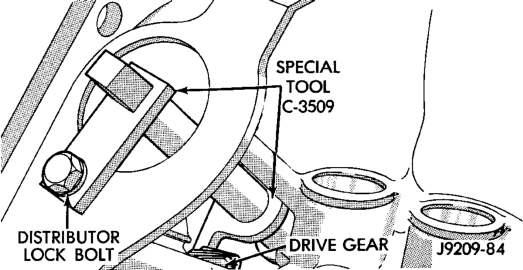
Position)
(3) Hold tool in position with a distributor lockplate bolt. This tool will restrict camshaft from being pushed in too far and prevent knocking out the welch plug in rear of cylinder block. Tool should remain installed until the camshaft and crankshaft sprockets and timing chain have been installed.
(4) Install camshaft thrust plate and chain oil tab. Make sure tang enters lower right hole in thrust plate. Tighten bolts to 24 N·m (210 in. lbs.) torque. Top edge of tab should be flat against thrust plate in order to catch oil for chain lubrication.
(5) Place both camshaft sprocket and crankshaft sprocket on the bench with timing marks on exact imaginary center line through both camshaft and crankshaft bores.
(6) Place timing chain around both sprockets. (7) Turn crankshaft and camshaft to line up with keyway location in crankshaft sprocket and in camshaft sprocket.
(8) Lift sprockets and chain (keep sprockets tight against the chain in position as described).
(9) Slide both sprockets evenly over their respective shafts and use a straightedge to check alignment of timing marks (Fig. 30).
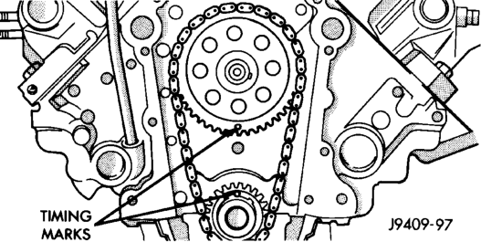
(10) Install the camshaft bolt/cup washer. Tighten bolt to 68 N·m (50 ft. lbs.) torque.
(11) Measure camshaft end play. Refer to Specifications for proper clearance. If not within limits install a new thrust plate.
(12) Each tappet reused must be installed in the same position from which it was removed. When camshaft is replaced, all of the tappets must be replaced.
CAMSHAFT BEARINGS
REMOVAL
NOTE: This procedure requires that the engine is removed from the vehicle.
(1) With engine completely disassembled, drive out rear cam bearing core hole plug.
(2) Install proper size adapters and horseshoe washers (part of Camshaft Bearing Remover/Installer
Tool C-3132-A) at back of each bearing shell. Drive out bearing shells (Fig. 31).
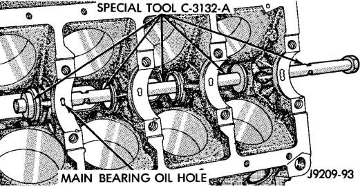
Tool C-3132-A
INSTALLATION
(1) Install new camshaft bearings with Camshaft Bearing Remover/Installer Tool C-3132-A by sliding the new camshaft bearing shell over proper adapter.
(2) Position rear bearing in the tool. Install horseshoe lock and by reversing removal procedure, carefully drive bearing shell into place.
(3) Install remaining bearings in the same manner. Bearings must be carefully aligned to bring oil holes into full register with oil passages from the main bearing. If the camshaft bearing shell oil holes are not in exact alignment, remove and install them correctly. Install a new core hole plug at the rear of camshaft. Be sure this plug does not leak.
CRANKSHAFT MAIN BEARINGS
REMOVAL
(1) Remove the oil pan. (2) Remove the oil pump from the rear main bearing cap. (3) Identify bearing caps before removal. Remove bearing caps one at a time.
(4) Remove upper half of bearing by inserting Crankshaft Main Bearing Remover/Installer Tool C-3059 into the oil hole of crankshaft (Fig. 32).
(5) Slowly rotate crankshaft clockwise, forcing out upper half of bearing shell.
INSTALLATION
Only one main bearing should be selectively fitted while all other main bearing caps are properly tightened. All bearing capbolts removed during service procedures are to be cleaned and oiled before installation.
When installing a new upper bearing shell, slightly chamfer the sharp edges from the plain side.
(1) Start bearing in place, and insert Crankshaft Main Bearing Remover/Installer Tool C-3059 into oil hole of crankshaft (Fig. 32).
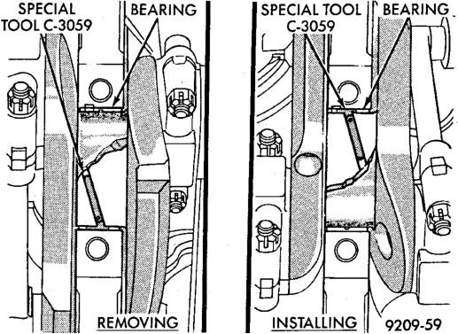
Installation with Tool C-3059
(2) Slowly rotate crankshaft counterclockwise sliding the bearing into position. Remove Tool C-3059. (3) Install the bearing caps. Clean and oil the bolts. Tighten the capbolts to 115 N·m (85 ft. lbs.) torque.
(4) Install the oil pump. (5) Install the oil pan.
DISTRIBUTOR DRIVE SHAFT BUSHING
REMOVAL
(1) Remove distributor, refer to Group 8D, Ignition Systems for the proper procedure.
(2) Remove the intake manifold (refer to Group 11, Exhaust System and Intake Manifold).
(3) Insert Distributor Drive Shaft Bushing Puller Tool C-3052 into old bushing and thread down until a tight fit is obtained (Fig. 33).
(4) Hold puller screw and tighten puller nut until bushing is removed.
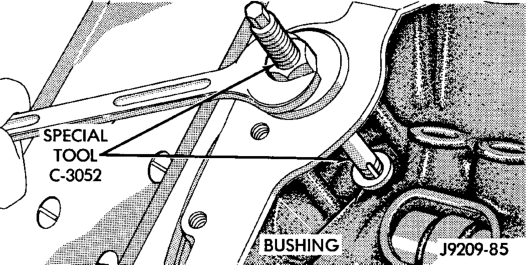
INSTALLATION
(1) Slide new bushing over burnishing end of Distributor Drive Shaft Bushing Driver/Burnisher Tool C-3053. Insert the tool and bushing into the bore.
(2) Drive bushing and tool into position, using a hammer (Fig. 34).
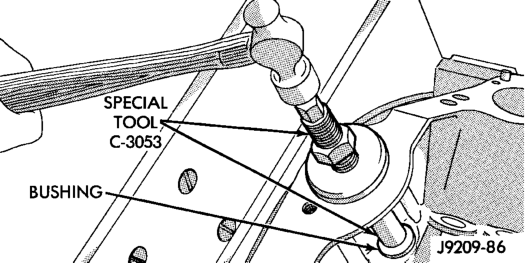
(3) As the burnisher is pulled through the bushing, the bushing is expanded tight in the block and burnished to correct size (Fig. 35). DO NOT ream this bushing.
CAUTION: This procedure MUST be followed when installing a new bushing or seizure to shaft may occur.
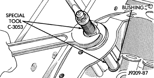
(4) Install the intake manifold (refer to Group 11, Exhaust System and Intake Manifold).
DISTRIBUTOR INSTALLATION
NOTE: Before installing the distributor, the oil pump drive shaft must be aligned to number one cylinder.
(1) Rotate crankshaft until No.1 cylinder is at top dead center on the firing stroke.
(2) When in this position, the timing mark of vibration damper should be under “0” on the timing indicator. (3) Install the shaft so that after the gear spirals into place, it will index with the oil pump shaft. The slot on top of oil pump shaft should be aligned towards the left front intake manifold attaching bolt hole (Fig. 36).
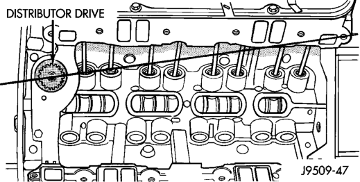
(4) Install distributor, refer to Group 8D, Ignition Systems for the proper procedure.
After the distributor has been installed, its rotational position must be set using the SET SYNC mode of the DRB scan tool. Refer to Checking Distributor Position following the Distributor Installation section in Group 8D, Ignition system.
Do not attempt to adjust ignition timing by rotating the distributor. It has no effect on ignition timing. Adjusting distributor position will effect fuel synchronization only.
OIL PAN
REMOVAL
(1) Disconnect the negative cable from the battery. (2) Raise the vehicle. (3) Remove the oil pan drain plug and drain the engine oil.
(4) Remove the oil filter. (5) Remove the starter (refer to Group 8B, Battery/ Starter/Generator Service).
(6) If equipped with an oil level sensor, disconnect the sensor.
(7) Position the cooler lines out of the way. (8) Disconnect the oxygen sensor. (9) Remove exhaust pipe. (10) Remove the oil pan bolts. Carefully slide the oil pan and gasket to the rear. If equipped with an oil level sensor, take care not to damage the sensor.
INSTALLATION
(1) Fabricate 4 alignment dowels from 5/16 x 1 1/2 inch bolts. Cut the head off the bolts and cut a slot into the top of the dowel. This will allow easier installation and removal with a screwdriver (Fig. 37). (2) Install the dowels in the cylinder block (Fig. 38).
(3) Apply small amount of Mopart Silicone Rubber Adhesive Sealant, or equivalent in the corner of the cap and the cylinder block.
(4) Slide the one-piece gasket over the dowels and onto the block.
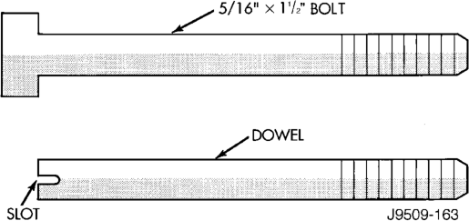
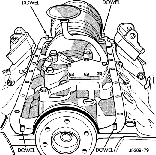
(5) Position the oil pan over the dowels and onto the gasket. If equipped with an oil level sensor, take care not to damage the sensor.
(6) Install the oil pan bolts. Tighten the bolts to 24 N·m (215 in. lbs.) torque.
(7) Remove the dowels. Install the remaining oil pan bolts. Tighten these bolts to 24 N·m (215 in. lbs.) torque.
(8) Install the drain plug. Tighten drain plug to 34 N·m (25 ft. lbs.) torque.
(9) Install exhaust pipe. (10) Connect the oxygen sensor. (11) Install the oil filter. (12) If equipped with an oil level sensor, connect the sensor.
(13) Install the starter (refer to Group 8B, Battery/ Starter/Generator Service).
(14) Move the cooler lines back into position. (15) Lower vehicle. (16) Connect the negative cable to the battery.
(17) Fill the oil pan with engine oil to the specified level.
WARNING: USE EXTREME CAUTION WHEN THE ENGINE IS OPERATING. DO NOT STAND IN A DIRECT LINE WITH THE FAN. DO NOT PUT YOUR HANDS NEAR THE PULLEYS, BELTS OR FAN. DO NOT WEAR LOOSE CLOTHING.
(18) Start the engine and inspect for leaks.
PISTON AND CONNECTING ROD ASSEMBLY
REMOVAL
(1) Remove the engine from the vehicle. (2) Remove the cylinder head. (3) Remove the oil pan. (4) Remove top ridge of cylinder bores with a reliable ridge reamer before removing pistons from cylinder block. Be sure to keep tops of pistons covered during this operation.
(5) Be sure the connecting rod and connecting rod cap are identified with the cylinder number. Remove connecting rod cap. Install connecting rod bolt guide set on connecting rod bolts.
(6) Pistons and connecting rods must be removed from top of cylinder block. When removing piston and connecting rod assemblies, rotate crankshaft to center the connecting rod in the cylinder bore and at BDC. Be careful not to nick crankshaft journals.
(7) After removal, install bearing cap on the mating rod.
INSTALLATION
(1) Be sure that compression ring gaps are staggered so that neither is in-line with oil ring rail gap.
(2) Before installing the ring compressor, make sure the oil ring expander ends are butted and the rail gaps located properly (Fig. 39).
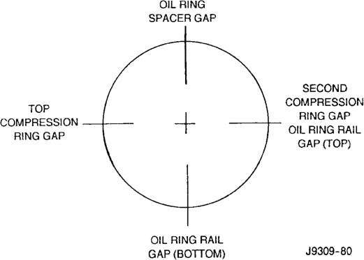
(3) Immerse the piston head and rings in clean engine oil. Slide Piston Ring Compressor Tool C-385 over the piston and tighten with the special wrench (part of Tool C-385). Be sure position of rings does not change during this operation.
(4) Install connecting rod bolt protectors on rod bolts, the long protector should be installed on the numbered side of the connecting rod.
(5) Rotate crankshaft so that the connecting rod journal is on the center of the cylinder bore. Be sure connecting rod and cylinder bore number are the same. Insert rod and piston into cylinder bore and guide rod over the crankshaft journal.
(6) Tap the piston down in cylinder bore, using a hammer handle. At the same time, guide connecting rod into position on crankshaft journal.
(7) The notch or groove on top of piston must be pointing toward front of engine. The larger chamfer of the connecting rod bore must be installed toward crankshaft journal fillet.
(8) Install rod caps. Be sure connecting rod, connecting rod cap and cylinder bore number are the same. Install nuts on cleaned and oiled rod bolts and tighten nuts to 61 N·m (45 ft. lbs.) torque.
(9) Install the oil pan. (10) Install the cylinder head. (11) Install the engine into the vehicle.
CRANKSHAFT
REMOVAL
(1) Remove the oil pan. (2) Remove the oil pump from the rear main bearing cap. (3) Remove the vibration damper. (4) Remove the timing chain cover. (5) Identify bearing caps before removal. Remove bearing caps and bearings one at a time.
(6) Lift the crankshaft out of the block. (7) Remove and discard the crankshaft rear oil seals.
(8) Remove and discard the front crankshaft oil seal.
INSTALLATION
(1) Clean Loctite 518 residue and sealant from the cylinder block and rear cap mating surface. Do this before applying the Loctite drop and the installation of rear cap.
(2) Lightly oil the new upper seal lips with engine oil.
(3) Install the new upper rear bearing oil seal with the white paint facing towards the rear of the engine.
(4) Position the crankshaft into the cylinder block. (5) Lightly oil the new lower seal lips with engine oil.
(6) Install the new lower rear bearing oil seal into the bearing cap with the white paint facing towards the rear of the engine.
(7) Apply 5 mm (0.20 in) drop of Loctite 518, or equivalent, on each side of the rear main bearing cap (Fig. 40). DO NOT over apply sealant or allow the sealant to contact the rubber seal. Assemble bearing cap to cylinder block immediately after sealant application.
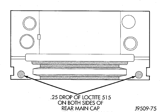
(8) To align the bearing cap, use cap slot, alignment dowel and cap bolts. DO NOT remove excess material after assembly. DO NOT strike rear cap more than 2 times for proper engagement.
(9) Clean and oil all cap bolts. Install all main bearing caps. Install all cap bolts and alternately tighten to 115 N·m (85 ft. lbs.) torque.
(10) Install oil pump. (11) Install the timing chain cover. (12) Install the vibration damper. (13) Apply Mopart Silicone Rubber Adhesive Sealant, or equivalent, at bearing cap to block joint to provide cap to block and oil pan sealing (Fig. 41). Apply enough sealant until a small amount is squeezed out. Withdraw nozzle and wipe excess sealant off the oil pan seal groove.
(14) Install new front crankshaft oil seal. (15) Immediately install the oil pan.
OIL PUMP
REMOVAL
(1) Remove the oil pan. (2) Remove the oil pump from rear main bearing cap.
INSTALLATION
(1) Install oil pump. During installation slowly rotate pump body to ensure driveshaft-to-pump rotor shaft engagement.
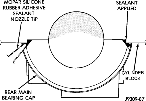
(2) Hold the oil pump base flush against mating surface on No.5 main bearing cap. Finger tighten pump attaching bolts. Tighten attaching bolts to 41 N·m (30 ft. lbs.) torque.
(3) Install the oil pan.
CRANKSHAFT OIL SEAL — FRONT
The oil seal can be replaced without removing the timing chain cover provided the cover is not misaligned.
(1) Disconnect the negative cable from the battery. (2) Remove vibration damper. (3) If front seal is suspected of leaking, check front oil seal alignment to crankshaft. The seal installation/alignment tool 6635, should fit with minimum interference. If tool does not fit, the cover must be removed and installed properly.
(4) Place a suitable tool behind the lips of the oil seal to pry the oil seal outward. Be careful not to damage the crankshaft seal bore of cover.
(5) Place the smaller diameter of the oil seal over Front Oil Seal Installation Tool 6635 (Fig. 42). Seat the oil seal in the groove of the tool.
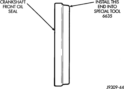
(6) Position the seal and tool onto the crankshaft (Fig. 43).
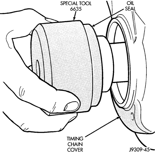
(7) Using the vibration damper bolt, tighten the bolt to draw the seal into position on the crankshaft (Fig. 44).
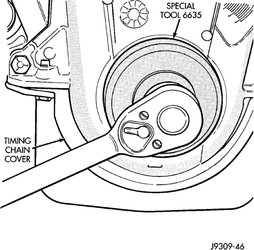
(8) Remove the vibration damper bolt and seal installation tool. (9) Inspect the seal flange on the vibration damper.
(10) Install the vibration damper. (11) Connect the negative cable to the battery.
CRANKSHAFT OIL SEALS — REAR
The service seal is a 2 piece, viton seal. The upper seal half can be installed with crankshaft removed from engine or with crankshaft installed. When a new upper seal is installed, install a new lower seal. The lower seal half can only be installed with the rear main bearing cap removed.
UPPER SEAL —CRANKSHAFT REMOVED
REMOVAL
(1) Remove the crankshaft. Discard the old upper seal.
INSTALLATION
(1) Clean the cylinder block rear cap mating surface. Make sure the seal groove is free of debris.
(2) Lightly oil the new upper seal lips with engine oil.
(3) Install the new upper rear bearing oil seal with the white paint facing towards the rear of the engine.
(4) Position the crankshaft into the cylinder block. (5) Lightly oil the new lower seal lips with engine oil.
(6) Install the new lower rear bearing oil seal into the bearing cap with the white paint facing towards the rear of the engine.
(7) Apply 5 mm (0.20 in) drop of Loctite 518, or equivalent, on each side of the rear main bearing cap (Fig. 45). DO NOT over apply sealant or allow the sealant to contact the rubber seal. Assemble bearing cap to cylinder block immediately after sealant application.
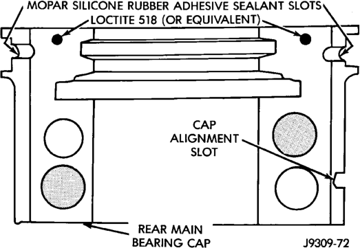
(8) To align the bearing cap, use cap slot, alignment dowel and cap bolts. DO NOT remove excess material after assembly. DO NOT strike rear cap more than 2 times for proper engagement.
(9) Clean and oil all cap bolts. Install all main bearing caps. Install all cap bolts and alternately tighten to 115 N·m (85 ft. lbs.) torque.
(10) Install oil pump. (11) Apply Mopar Silicone Rubber Adhesive Sealant, or equivalent, at bearing cap to block joint to provide cap to block and oil pan sealing (Fig. 46). Apply enough sealant until a small amount is squeezed out. Withdraw nozzle and wipe excess sealant off the oil pan seal groove.
(12) Install new front crankshaft oil seal. (13) Immediately install the oil pan.
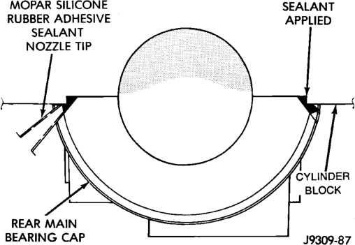
UPPER SEAL —CRANKSHAFT INSTALLED
REMOVAL
(1) Remove the oil pan. (2) Remove the oil pump from the rear main bearing cap. (3) Remove the rear main bearing cap. Remove and discard the old lower oil seal.
(4) Carefully remove and discard the old upper oil seal.
INSTALLATION
(1) Clean the cylinder block mating surfaces before oil seal installation. Check for burr at the oil hole on the cylinder block mating surface to rear cap.
(2) Lightly oil the new upper seal lips with engine oil. To allow ease of installation of the seal, loosen at least the 2 main bearing caps forward of the rear bearing cap.
(3) Rotate the new upper seal into the cylinder block being careful not to shave or cut the outer surface of the seal. To assure proper installation, use the installation tool provided with the kit. Install the new seal with the white paint facing towards the rear of the engine.
(4) Install the new lower rear bearing oil seal into the bearing cap with the white paint facing towards the rear of the engine.
(5) Apply 5 mm (0.20 in) drop of Loctite 518, or equivalent, on each side of the rear main bearing cap (Fig. 45). DO NOT over apply sealant or allow the sealant to contact the rubber seal. Assemble bearing cap to cylinder block immediately after sealant application. Be sure the white paint faces toward the rear of the engine.
(6) To align the bearing cap, use cap slot, alignment dowel and cap bolts. DO NOT remove excess material after assembly. DO NOT strike rear cap more than 2 times for proper engagement.
(7) Install the rear main bearing cap with cleaned and oiled cap bolts. Alternately tighten ALL cap bolts to 115 N·m (85 ft. lbs.) torque.
(8) Install oil pump. (9) Apply Mopar Silicone Rubber Adhesive Sealant, or equivalent, at bearing cap to block joint to provide cap to block and oil pan sealing (Fig. 46). Apply enough sealant until a small amount is squeezed out. Withdraw nozzle and wipe excess sealant off the oil pan seal groove.
(10) Immediately install the oil pan.
LOWER SEAL
REMOVAL
(1) Remove the oil pan. (2) Remove the oil pump from the rear main bearing cap. (3) Remove the rear main bearing cap and discard the old lower seal.
INSTALLATION
(1) Clean the rear main cap mating surfaces including the oil pan gasket groove. (2) Carefully install a new upper seal (refer to Upper Seal Replacement - Crankshaft Installed procedure above).
(3) Lightly oil the new lower seal lips with engine oil.
(4) Install a new lower seal in bearing cap with the white paint facing the rear of engine.
(5) Apply 5 mm (0.20 in) drop of Loctite 518, or equivalent, on each side of the rear main bearing cap (Fig. 45). DO NOT over apply sealant or allow the sealant to contact the rubber seal. Assemble bearing cap to cylinder block immediately after sealant application.
(6) To align the bearing cap, use cap slot, alignment dowel and cap bolts. DO NOT remove excess material after assembly. DO NOT strike rear cap more than 2 times for proper engagement.
(7) Install the rear main bearing cap with cleaned and oiled cap bolts. Alternately tighten the cap bolts to 115 N·m (85 ft. lbs.) torque.
(8) Install oil pump. (9) Apply Mopar Silicone Rubber Adhesive Sealant, or equivalent, at bearing cap to block joint to provide cap to block and oil pan sealing (Fig. 46). Apply enough sealant until a small amount is squeezed out. Withdraw nozzle and wipe excess sealant off the oil pan seal groove.
(10) Immediately install the oil pan.
ENGINE CORE OIL AND CAMSHAFT PLUGS
Engine core plugs have been pressed into the oil galleries behind the camshaft thrust plate (Fig. 47). This will reduce internal leakage and help maintain higher oil pressure at idle.
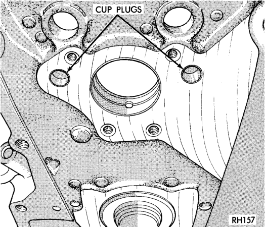
REMOVAL
(1) Using a blunt tool such as a drift or a screwdriver and a hammer, strike the bottom edge of the cup plug (Fig. 48).
(2) With the cup plug rotated, grasp firmly with pliers or other suitable tool and remove plug (Fig. 48).
INSTALLATION
Thoroughly clean inside of cup plug hole in cylinder block or head. Be sure to remove old sealer.
Be certain the new plug is cleaned of all oil or grease.
(1) Coat edges of plug and core hole with Mopar Gasket Maker, or equivalent.
CAUTION: DO NOT drive cup plug into the casting, as restricted coolant flow can result and cause serious engine problems.
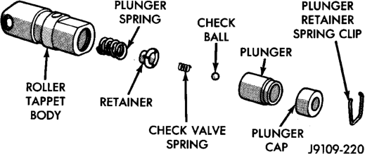
(2) Using proper plug drive, drive cup plug into hole. The sharp edge of the plug should be at least 0.50 mm (0.020 in.) inside the lead-in chamfer.
(3) It is not necessary to wait for curing of the sealant. The cooling system can be filled and the vehicle placed in service immediately.
DISASSEMBLY AND ASSEMBLY
HYDRAULIC TAPPETS
CAUTION: The plunger and tappet bodies are not interchangeable. The plunger and valve must always be fitted to the original body. It is advisable to work on one tappet at a time to avoid mixing of parts. Mixed parts are not compatible. DO NOT disassemble a tappet on a dirty work bench.
DISASSEMBLE
(1) Pry out plunger retainer spring clip (Fig. 49). (2) Clean varnish deposits from inside of tappet body above plunger cap.
(3) Invert tappet body and remove plunger cap, plunger, check valve, check valve spring, check valve retainer and plunger spring (Fig. 49). Check valve could be flat or ball.
ASSEMBLE
(1) Clean all tappet parts in a solvent that will remove all varnish and carbon.
(2) Replace tappets that are unfit for further service with new assemblies.
(3) If plunger shows signs of scoring or wear, install a new tappet assembly. If valve is pitted, or valve seat on end of plunger is prevented from seating, install a new tappet assembly. (4) Assemble tappets (Fig. 49).
VALVE SERVICE
VALVE GUIDES
Measure valve stem guide clearance as follows: (1) Install Valve Guide Sleeve Tool C-3973 over valve stem and install valve (Fig. 50). The special sleeve places the valve at the correct height for checking with a dial indicator.
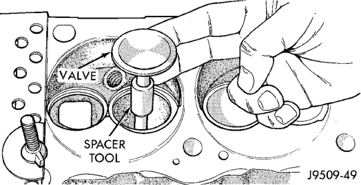
(2) Attach Dial Indicator Tool C-3339 to cylinder head and set it at right angle of valve stem being measured (Fig. 51).
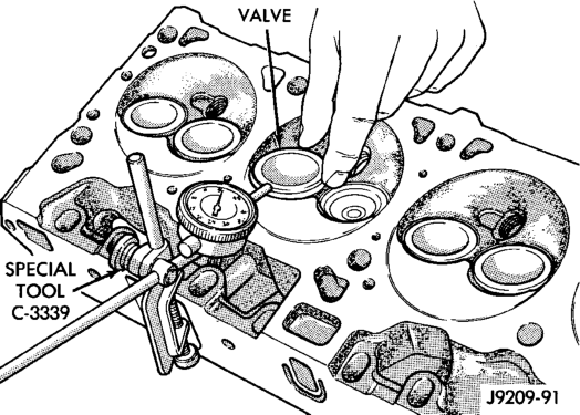
(3) Move valve to and from the indicator. The total dial indicator reading should not exceed 0.432 mm (0.017 inch). Ream the guides for valves with oversize stems if dial indicator reading is excessive or if the stems are scuffed or scored.
(4) Service valves with oversize stems are available (Fig. 52).
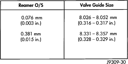
(5) Slowly turn reamer by hand and clean guide thoroughly before installing new valve. Ream the valve guides from standard to 0.381 mm (0.015 inch). Use a 2 step procedure so the valve guides are reamed true in relation to the valve seat:
• Step 1—Ream to 0.0763 mm (0.003 inch). • Step 2—Ream to 0.381 mm (0.015 inch).
REFACING VALVES AND VALVE SEATS
The intake and exhaust valves have a 43-1/4° to 43-3/4° face angle and a 44-1/4° to 44-3/4° seat angle (Fig. 53).
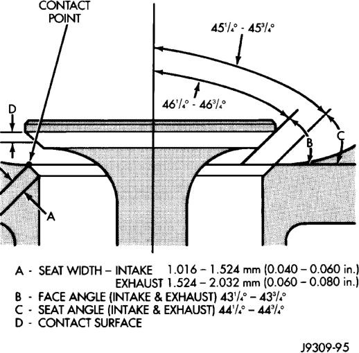
VALVES
Inspect the remaining margin after the valves are refaced (Fig. 54). Valves with less than 1.190 mm (0.047 inch) margin should be discarded.
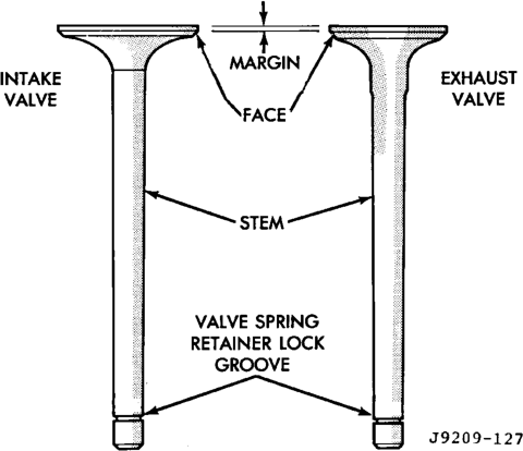
VALVE SEATS
CAUTION: DO NOT un-shroud valves during valve seat refacing (Fig. 55).
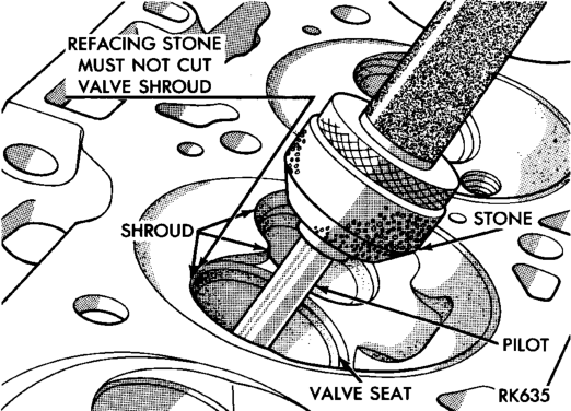
(1) When refacing valve seats, it is important that the correct size valve guide pilot be used for reseating stones. A true and complete surface must be obtained.
(2) Measure the concentricity of valve seat using a dial indicator. Total runout should not exceed 0.051 mm (0.002 inch) total indicator reading.
(3) Inspect the valve seat with Prussian blue to determine where the valve contacts the seat. To do this, coat valve seat LIGHTLY with Prussian blue then set valve in place. Rotate the valve with light pressure. If the blue is transferred to the center of valve face, contact is satisfactory. If the blue is transferred to the top edge of valve face, lower valve seat with a 15° stone. If the blue is transferred to bottom edge of valve face raise valve seat with a 60° stone.
(4) When seat is properly positioned the width of intake seats should be 1.016-1.524 mm (0.040-0.060 inch). The width of the exhaust seats should be 1.524-2.032 mm (0.060-0.080 inch).
VALVE SPRING INSPECTION
Whenever valves have been removed for inspection, reconditioning or replacement, valve springs should be tested. As an example the compression length of the spring to be tested is 1-5/16 inch. Turn table of Universals Valve Spring Tester Tool until surface is in line with the 1-5/16 inch mark on the threaded stud. Be sure the zero mark is to the front (Fig. 56). Place spring over stud on the table and lift compressing lever to set tone device. Pull on torque wrench until ping is heard. Take reading on torque wrench at this instant. Multiply this reading by 2. This will give the spring load at test length. Fractional measurements are indicated on the table for finer adjustments. Refer to specifications to obtain specified height and allowable tensions. Discard the springs that do not meet specifications.
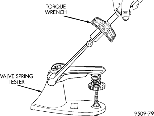
Length
OIL PUMP
DISASSEMBLE
(1) Remove the relief valve as follows:
(a) Remove cotter pin. Drill a 3.175 mm (1/8 inch) hole into the relief valve retainer cap and insert a self-threading sheet metal screw. (b) Clamp screw into a vise and while supporting oil pump, remove cap by tapping pump body using a soft hammer. Discard retainer cap and remove spring and relief valve (Fig. 57).
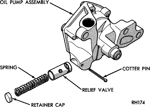
(2) Remove oil pump cover (Fig. 58). (3) Remove pump outer rotor and inner rotor with shaft (Fig. 58).
(4) Wash all parts in a suitable solvent and inspect carefully for damage or wear.
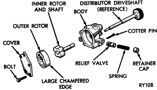
ASSEMBLE
(1) Install pump rotors and shaft, using new parts as required.
(2) Position the oil pump cover onto the pump body. Tighten cover bolts to 11 N·m (95 in. lbs.) torque.
(3) Install the relief valve and spring. Insert the cotter pin.
(4) Tap on a new retainer cap. (5) Prime oil pump before installation by filling rotor cavity with engine oil.
CYLINDER BLOCK
DISASSEMBLE
Engine assembly removed from vehicle: (1) Remove the cylinder head. (2) Remove the oil pan.
(3) Remove the piston and connecting rod assemblies.
ASSEMBLE
(1) Install the piston and connecting rod assembly. (2) Install the oil pan. (3) Install the cylinder head. (4) Install the engine into the vehicle.
CLEANING AND INSPECTION
CYLINDER HEADS
CLEANING
Clean all surfaces of cylinder block and cylinder heads.
Clean cylinder block front and rear gasket surfaces using a suitable solvent.
INSPECTION
Inspect all surfaces with a straightedge if there is any reason to suspect leakage. If out-of-flatness exceeds 0.00075 mm/mm (0.00075 inch/inch) times the span length in inches in any direction, either replace head or lightly machine the head surface.
FOR EXAMPLE: A 305 mm (12 inch) span is 0.102 mm (0.004 inch) out-of-flat. The allowable outof-flat is 305 x 0.00075 (12 x 0.00075) equals 0.23 mm (0.009 inch). This amount of out-of-flat is acceptable.
The cylinder head surface finish should be 1.78-3.00 microns (70-125 micro inches).
Inspect push rods. Replace worn or bent rods.
PISTON AND CONNECTING ROD ASSEMBLY
INSPECTION
Check the crankshaft connecting rod journal for excessive wear, taper and scoring.
Check the cylinder block bore for out-of-round, taper, scoring and scuffing.
Check the pistons for taper and elliptical shape before they are fitted into the cylinder bore (Fig. 59).
CRANKSHAFT JOURNALS
The crankshaft connecting rod and main journals should be checked for excessive wear, taper and scoring. The maximum taper or out-of-round on any crankshaft journal is 0.025 mm (0.001 inch).
Journal grinding should not exceed 0.305 mm (0.012 inch) under the standard journal diameter. DO NOT grind thrust faces of No.3 main bearing. DO NOT nick crank pin or bearing fillets. After grinding, remove rough edges from crankshaft oil holes and clean out all oil passages.
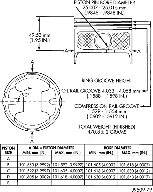
CAUTION: After any journal grind, it is important that the final paper or cloth polish be in the same direction as the engine rotates.
OIL PAN
CLEANING
Clean the block and pan gasket surfaces. Trim or remove excess sealant film in the rear main cap oil pan gasket groove. DO NOT remove the sealant inside the rear main cap slots.
If present, trim excess sealant from inside the engine.
Clean oil pan in solvent and wipe dry with a clean cloth.
Clean oil screen and pipe thoroughly in clean solvent. Inspect condition of screen.
INSPECTION
Inspect oil drain plug and plug hole for stripped or damaged threads. Repair as necessary.
Inspect oil pan mounting flange for bends or distortion. Straighten flange, if necessary.
OIL PUMP
INSPECTION
Mating surface of the oil pump cover should be smooth. Replace pump assembly if cover is scratched or grooved.
Lay a straightedge across the pump cover surface (Fig. 60). If a 0.038 mm (0.0015 inch) feeler gauge can be inserted between cover and straightedge, pump assembly should be replaced.
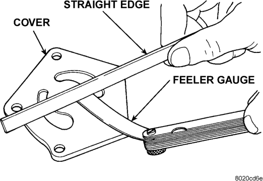
Measure thickness and diameter of OUTER rotor. If outer rotor thickness measures 20.9 mm (0.825 inch) or less or if the diameter is 62.7 mm (2.469 inches) or less, replace outer rotor (Fig. 61).
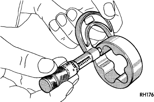
If inner rotor measures 20.9 mm (0.825 inch) or less, replace inner rotor and shaft assembly (Fig. 62).
Slide outer rotor into pump body. Press rotor to the side with your fingers and measure clearance between rotor and pump body (Fig. 63). If clearance is 0.356 mm (0.014 inch) or more, replace oil pump assembly.
Install inner rotor and shaft into pump body. If clearance between inner and outer rotors is 0.203
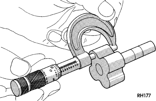

Housing
mm (0.008 inch) or more, replace shaft and both rotors (Fig. 64).
Place a straightedge across the face of the pump,

straightedge, replace pump assembly (Fig. 65).
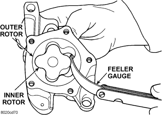
Inspect oil pressure relief valve plunger for scoring and free operation in its bore. Small marks may be removed with 400-grit wet or dry sandpaper.
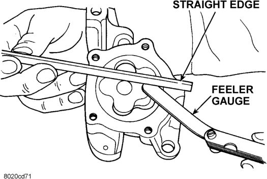
The relief valve spring has a free length of approximately 49.5 mm (1.95 inches). The spring should test between 19.5 and 20.5 pounds when compressed to 34 mm (1-11/32 inches). Replace spring that fails to meet these specifications (Fig. 66).
If oil pressure was low and pump is within specifications, inspect for worn engine bearings or other reasons for oil pressure loss.
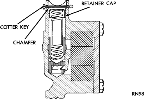
CYLINDER BLOCK
CLEANING
Clean cylinder block thoroughly and check all core hole plugs for evidence of leaking.
INSPECTION
Examine block for cracks or fractures. The cylinder walls should be checked for out-ofround and taper with Cylinder Bore Indicator Tool C-119. The cylinder block should be bored and honed with new pistons and rings fitted if:
• The cylinder bores show more than 0.127 mm (0.005 in.) out-of-round.
• The cylinder bores show a taper of more than 0.254 mm (0.010 in.).
• The cylinder walls are badly scuffed or scored. Boring and honing operation should be closely coordinated with the fitting of pistons and rings, so that specified clearances can be maintained.
OIL LINE PLUG
The oil line plug is located in the vertical passage at the rear of the block between the oil-to-filter and oil-from-filter passages (Fig. 67). Improper installation or plug missing could cause erratic, low, or no oil pressure.
The oil plug must come out the bottom. Use flat dowel, down the oil pressure sending unit hole from the top, to remove oil plug.
(1)
Remove oil pressure sending unit from back of block.
(2) Insert a 3.175 mm (1/8 in.) finish wire, or equivalent, into passage.
(3) Plug should be 190.0 to 195.2 mm (7-1/2 to 7-11/16 in.) from machined surface of block (Fig. 67). If plug is too high, use a suitable flat dowel to position properly.
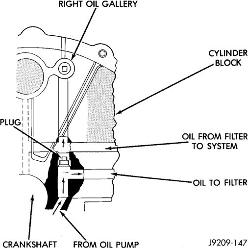
(4) If plug is too low, remove oil pan and No. 4 main bearing cap. Use suitable flat dowel to position properly. Coat outside diameter of plug with Mopar Stud and Bearing Mount Adhesive, or equivalent. Plug should be 54.0 to 57.7 mm (2-1/8 to 2-5/16 in.) from bottom of the block.
SPECIFICATIONS
5.9L ENGINE SPECIFICATIONS
GENERAL INFORMATION
Engine Type. . . . . . . . . . . . . . . . . . . . . .90° V-8 OHV Bore and Stroke . . .101.6 x 90.9 mm (4.00 x 3.58 in.) Displacement . . . . . . . . . . . . . . . . . . . .5.9L (360 c.i.) Compression Ratio . . . . . . . . . . . . . . . . . . . . . . .9.1:1 Firing Order. . . . . . . . . . . . . . . . . .1–8–4–3–6–5–7–2 Lubrication . . . .Pressure Feed – Full Flow Filtration Cooling System . .Liquid Cooled – Forced Circulation Cylinder Block. . . . . . . . . . . . . . . . . . . . . . .Cast Iron Cylinder Head . . . . . . . . . . . . . . . . . . . . . . .Cast Iron Crankshaft. . . . . . . . . . . . . . . . . . . . . . .Nodular Iron Camshaft. . . . . . . . . . . . . . . . . . . .Nodular Cast Iron Combustion Chambers . . . .Wedge - High Swirl Valve
Shrouding Pistons . . . . . . . . . . . . . . . . .Aluminum Alloy w/strut Connecting Rods. . . . . . . . . . . . . . . . . . .Forged Steel Compression Pressure . . . .689.5 kPa (100 psi) (Min.)
CAMSHAFT
Bearing Diameter No. 1 . . . . . . .50.800 – 50.825 mm (2.000 – 2.001 in.) No. 2 . . . . . . .50.394 – 50.419 mm (1.984 – 1.985 in.) No. 3 . . . . . . .50.013 – 50.038 mm (1.969 – 1.970 in.) No. 4 . . . . . . .49.606 – 49.632 mm (1.953 – 1.954 in.) No. 5 . . . . .39.688 – 39.713 mm (1.5625 – 1.5635 in.) Bearing Journal Diameter No. 1 . . . . . . .50.749 – 50.775 mm (1.998 – 1.999 in.) No. 2 . . . . . . .50.343 – 50.368 mm (1.982 – 1.983 in.) No. 3 . . . . . . .49.962 – 49.987 mm (1.967 – 1.968 in.) No. 4 . . . . . . .49.555 – 49.581 mm (1.951 – 1.952 in.) No. 5 . . . . .39.637 – 39.662 mm (1.5605 – 1.5615 in.) Bearing to Journal Clearance Standard . . . .0.0254 – 0.0762 mm (0.001 – 0.003 in.)
Service Limit . . . . . . . . . . . . .0.127 mm (0.005 in.) Camshaft End Play End Play . . . . . .0.051 – 0.254 mm (0.002 – 0.010 in.)
CONNECTING RODS
Piston Pin bore Diameter . . . . . .24.966 – 24.978 mm
(0.9829 – 0.9834 in.) Side Clearance . . . . . . . . . . . . . . . .0.152 – 0.356 mm
(0.006 – 0.014 in.)
CRANKSHAFT
Rod Journal Diameter . . . .53.950 – 53.975 mm (2.124 – 2.125 in.) Out of Round (Max.). . . . . . . . .0.0254 mm (0.001 in.) Taper (Max.). . . . . . . . . . . . . . .0.0254 mm (0.001 in.)
Rod Journal Bearing Clearance . . . . . . . . . . . . .0.013 – 0.056 mm
(0.0005 – 0.0022 in.) Service Limit . . . . . . . . . . . .0.0762 mm (0.003 in.) Main Bearing Journal Diameter . .71.361 – 71.387 mm (2.8095 – 2.8105 in.) Out of Round (Max.) . . . . . . . . .0.127 mm (0.001 in.) Taper (Max.). . . . . . . . . . . . . . .0.0254 mm (0.001 in.) Bearing Clearance (#1 Journal) . . .0.013 – 0.038 mm
(0.0005 – 0.0015 in.) Service Limit (#1 Journal) . . . . . . . . . . .0.0381 mm
(0.0015 in.)
Bearing Clearance (#2-5 Journals) . . .0.013 - 0.051 mm
(0.0005 - 0.002 in.)
Service Limit (#2-5 Journals) . . . . . . . . .0.064 mm
(0.0025 in.) Crankshaft End Play End Play . . . . . .0.051 – 0.178 mm (0.002 – 0.007 in.)
Service Limit . . . . . . . . . . . . .0.254 mm (0.010 in.)
CYLINDER BLOCK
Cylinder Bore Diameter . . . .101.60 – 101.65 mm (4.000 – 4.002 in.) Out of Round (Max.) . . . . . . . . .0.127 mm (0.005 in.) Taper (Max.) . . . . . . . . . . . . . . .0.254 mm (0.010 in.) Lifter Bore Diameter . . . .22.99 – 23.01 mm (0.9051 – 0.9059 in.) Distributor Drive Bushing (Press Fit) Bushing to Bore Interference . . .0.0127 – 0.3556 mm
(0.0005 – 0.0140 in.) Shaft to Bushing Clearance . . . .0.0178 – 0.0686 mm
(0.0007 – 0.0027 in.)
CYLINDER HEAD AND VALVES
Valve Seat Angle . . . . . . . . . . . . . . . . . . . . . . . . .44.25° – 44.75° Runout (Max.) . . . . . . . . . . . . .0.0762 mm (0.003 in.) Width (Finish) – Intake . . . . . . . . .1.016 – 1.524 mm
(0.040 – 0.060 in.) Width (Finish) – Exhaust . . . . . . . .1.524 – 2.032 mm
(0.060 – 0.080 in.) Valves Face Angle . . . . . . . . . . . . . . . . . . . . .43.25° – 43.75° Head Diameter – Intake . . . . . .47.752 mm (1.88 in.) Head Diameter – Exhaust. . . . . . . .41.072 (1.617 in.) Length (Overall) – Intake . . . . . .126.21 – 126.85 mm
(4.969 – 4.994 in.) Length (Overall) – Exhaust . . . .126.44 – 127.30 mm
(4.978 – 5.012 in.)
Valve Seat Lift (@ zero lash) – Intake . . . .10.414 mm (0.410 in.) Lift (@ zero lash) – Exhaust. . .10.592 mm (0.417 in.) Stem Diameter – Intake. . . . . . . . .9.449 – 9.474 mm
(0.372 – 0.373 in.) Stem Diameter – Exhaust . . . . . . .9.423 – 9.449 mm
(0.371 – 0.372 in.) Guide Bore . . . .9.500 – 9.525 mm (0.374 – 0.375 on.) Stem to Guide Clearance –
Intake. . . .0.0254 – 0.0762 mm (0.001 – 0..003 in.) Stem to Guide Clearance –
Exhaust. . .0.0508 – 0.1016 mm (0.002 – 0.004 in.) Service Limit . . . . . . . . . . . . . . . .0.4318 (0.017 in.) Valve Springs Free Length . . . . . . . . . . . . . . .49.962 mm (1.967 in.) Spring Tension – (valve closed) . .378 N @ 41.66 mm
(85 lbs. @ 1.64 in.) Spring Tension – (valve open). . . .890 N @ 30.89 mm
(200 lbs. @ 1.212 in.) Number of Coils. . . . . . . . . . . . . . . . . . . . . . . . . . .6.8 Installed Height. . . . . . . . . . . . . .41.66 mm (1.64 in.) Wire Diameter . . . . . . . . . . . . . . .4.50 mm (0.177 in.)
HYDRAULIC TAPPETS
Body Diameter . . . . . . . . . . . . . .22.949 – 22.962 mm
(0.9035 – 0.9040 in.) Clearance (to bore) . . . . . . . . . . .0.0279 – 0.0610 mm
(0.0011 – 0.0024 in.) Dry Lash. . . . . .1.524 – 5.334 mm (0.060 – 0.210 in.) Push Rod Length . . . . . . . . . . . .175.64 – 176.15 mm
(6.915 – 6.935 in.)
OIL PRESSURE
Curb Idle (Min.*) . . . . . . . . . . . . . . . .41.4 kPa (6 psi) 3000 rpm. . . . . . . . . . . . .207 – 552 kPa (30 – 80 psi) Oil Pressure Bypass Valve Setting. . . . .62 – 103 kPa
(9 – 15 psi) Switch Actuating Pressure. . . . . . . . .34.5 – 48.3 kPa
(5 – 7 psi)
CAUTION: If oil pressure is zero at curb idle, DO NOT RUN ENGINE.
OIL PUMP
Clearance over Rotors (Max.) . .0.1016 mm (0.004 in.) Cover Out of Flat (Max.) . . . .0.0381 mm (0.0015 in.)

Outer Rotor Thickness (Min.). . . .20.955 mm (0.825 in.)
Tip Clearance between Rotors (Max.) . . . .0.2032 mm
(0.008 in.)
PISTONS
Clearance at Top of Skirt . . . . . . . .0.013 – 0.038 mm
(0.0005 – 0.0015 in.) Land Clearance (Diam.) . . . . . . . . .0.508 – 0.660 mm
(0.020 – 0.026 in.) Piston Length . . . . . . . . . . . . . . .81.03 mm (3.19 in.)
Piston Ring Groove Depth — #1&2 .. .4.761 — 4.912 mm
(0.187 — 0.193 in.)
Piston Ring Groove Depth – #3 . . .3.996 – 4.177 mm
(0.157 – 0.164 in.) Weight . . . . . . . .582 – 586 grams (20.53 – 20.67 oz.)
PISTON PINS
Clearance in Piston . . . . . . . . . . . .0.006 – 0.019 mm
(0.00023 – 0.00074 in.)
Diameter .. . .25.007 — 25.015 mm (0.9845 — 0.9848 in.)
End Play . . . . . . . . . . . . . . . . . . . . . . . . . . . . .NONE Length . . . . . . . . . . .67.8 – 68.3 mm (2.67 – 2.69 in.)
PISTON RINGS
Ring Gap Compression Ring (Top) . . . . . . . . . . .0.30 – 0.55 mm
(0.012 – 0.022 in.) Compression Ring (2nd) . . . . . . . . . . .0.55 – 0.80 mm
(0.022 – 0.031 in.) Oil Control (Steel Rails) . . . . . . . . .0.381 – 1.397 mm
(0.015 – 0.055 in.) Ring Side Clearance Compression Rings. . . . . . . . . . . . .0.040 – 0.085 mm
(0.0016 – 0.0033 in.) Oil Ring (Steel Rails) . . . . . . . . . . . . .0.05 – 0.21 mm
(0.002 – 0.008 in.) Ring Width Compression rings . . . . . . . . . . . . .1.530 – 1.555 mm
(0.060 – 0.061 in.) Oil Ring (Steel Rails) – Max.. . . . . .0.447 –0.473 mm
(0.018 – 0.019 in.)
VALVE TINING
Exhaust Valve Closes (ATDC). . . . . . . . . . . . . . . . . . . . . . . . . . . .33° Opens (BBDC). . . . . . . . . . . . . . . . . . . . . . . . . . . .56° Duration . . . . . . . . . . . . . . . . . . . . . . . . . . . . . . .269° Intake Valve Closes (ATDC). . . . . . . . . . . . . . . . . . . . . . . . . . . .62° Opens (BBDC) . . . . . . . . . . . . . . . . . . . . . . . . . . . .7° Duration . . . . . . . . . . . . . . . . . . . . . . . . . . . . . . .249° Valve Overlap . . . . . . . . . . . . . . . . . . . . . . . . . . . .41°
OVERSIZE AND UNDERSIZE ENGINE COMPONENT MARKINGS
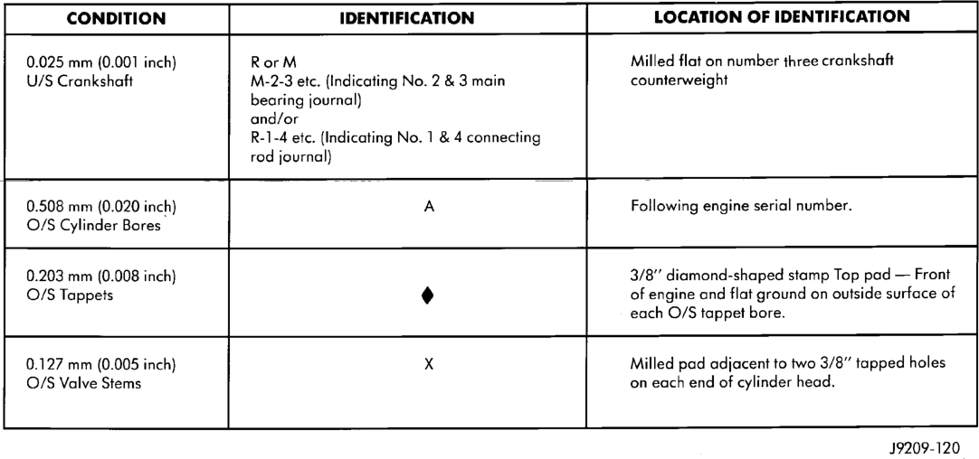
0.025 mm (0.001 inch) RorM Milled flat on number three crankshaft
U/S Crankshaft M-2-3 etc. (Indicating No. 2 & 3 main counterweight
bearing journal)
and/or
R-1-4 etc. (Indicating No. 1 & 4 connecting
rod journal)
0.508 mm (0.020 inch) A Following engine serial number.
O/S Cylinder Bores
0.203 mm (0.008 inch) 3/8" diamond-shaped stamp Top pad — Front
O/S Tappets of engine and flat ground on outside surface of
each O/S tappet bore.
0.127 mm (0.005 inch) xX Milled pad adjacent to two 3/8” tapped holes
O/S Valve Stems on each end of cylinder head.
J9209-120
5.9L TORQUE SPECIFICATIONS
DESCRIPTION TORQUE Camshaft Sprocket
Bolt . . . . . . . . . . . . . . . . . . . . . .68 N·m (50 ft. lbs.) Camshaft Thrust Plate
Bolts . . . . . . . . . . . . . . . . . . . . .24 N·m (18 ft. lbs.) Chain Case Cover
Bolts . . . . . . . . . . . . . . . . . . . . .41 N·m (30 ft. lbs.) Connecting Rod Cap
Bolts . . . . . . . . . . . . . . . . . . . . .61 N·m (45 ft. lbs.) Crankshaft Main Bearing Cap
Bolts . . . . . . . . . . . . . . . . . . . .115 N·m (85 ft. lbs.) Crankshaft Pulley
Bolts . . . . . . . . . . . . . . . . . . . .24 N·m (210 in. lbs.) Cylinder Head Bolts
Step 1 – Initial . . . . . . . . . . . . .68 N·m (50 ft. lbs.) Step 2 – Final . . . . . . . . . . . .143 N·m (105 ft. lbs.) Cylinder Head Cover
Bolts . . . . . . . . . . . . . . . . . . . . .11 N·m (95 in. lbs.) Exhaust Manifold to Cylinder Head
Bolts/Nuts . . . . . . . . . . . . . . . . .34 N·m (25 ft. lbs.) Flywheel
Bolts . . . . . . . . . . . . . . . . . . . . .75 N·m (55 ft. lbs.) Front Engine Mount Bracket to Block
Bolts . . . . . . . . . . . . . . . . . . . . .81 N·m (60 ft. lbs.) Front Engine Mount
Through Bolt/Nut . . . . . . . . . . .68 N·m (50 ft. lbs.) Generator Mounting
Bolts . . . . . . . . . . . . . . . . . . . . .41 N·m (30 ft. lbs.) Intake Manifold
Bolts . . . . . . . . . .Refer to procedure in this section
DESCRIPTION TORQUE Oil Pan
Bolts . . . . . . . . . . . . . . . . . . . .24 N·m (215 in. lbs.) Oil Pan Drain Plug
Plug. . . . . . . . . . . . . . . . . . . . . .34 N·m (25 ft. lbs.) Oil Pump
Bolts . . . . . . . . . . . . . . . . . . . . .41 N·m (30 ft. lbs.) Oil Pump Cover
Bolts . . . . . . . . . . . . . . . . . . . . .11 N·m (95 in. lbs.) Rear Mount Insulator to Support Bracket
Nuts . . . . . . . . . . . . . . . . . . . . .47 N·m (35 ft. lbs.) Rear Mount Insulator to Crossmember
Nut . . . . . . . . . . . . . . . . . . . . . .47 N·m (35 ft. lbs.) Rear Support Bracket to Transmission
Bolts . . . . . . . . . . . . . . . . . . . .102 N·m (75 ft. lbs.) Rocker Arm
Bolts . . . . . . . . . . . . . . . . . . . . .28 N·m (21 ft. lbs.) Spark Plugs
Plugs . . . . . . . . . . . . . . . . . . . . .41 N·m (30 ft. lbs.) Starter Mounting
Bolts . . . . . . . . . . . . . . . . . . . . .68 N·m (50 ft. lbs.) Thermostat Housing
Bolts . . . . . . . . . . . . . . . . . . . .25 N·m (225 in. lbs.) Throttle Body
Bolts . . . . . . . . . . . . . . . . . . . .23 N·m (200 in. lbs.) Torque Converter Drive Plate
Bolts . . . . . . . . . . . . . . . . . . . .31 N·m (270 in. lbs.) Transmission Support Bracket
Bolts . . . . . . . . . . . . . . . . . . . .102 N·m (75 ft. lbs.) Transmission Support Spacer to
Insulator Mounting Plate – (4wd) Nuts. . . . . . . . . . . . . . . . . . . .204 N·m (150 ft. lbs.)
DESCRIPTION TORQUE Vibration Damper
Bolt . . . . . . . . . . . . . . . . . . . .183 N·m (135 ft. lbs.) Water Pump to Chain Case Cover
Bolt . . . . . . . . . . . . . . . . . . . . . .41 N·m (30 ft. lbs.)
SPECIAL TOOLS
5.9L ENGINE