Cooling System — part 1 of 2 — 1998 Jeep Grand Cherokee ZJ Export Service Manual
← Contents 1 2
Pages 227–286 · 60 pages · 22 words repaired
system is pressurized and uses a centrifugal water pump to circulate coolant throughout the system.
Vehicles equipped with the 5.9L engine receive a “max” cooling package which consists of a heavy duty radiator and an electric cooling fan. This package will provide additional cooling capacity for vehicles used under extreme conditions such as trailer towing in high ambient temperatures.
Components
The cooling system consists of: • A radiator • Viscous Cooling Fan (4.0L/5.2L Engines) • Electric Cooling Fan (5.9L Engines) • Thermal viscous fan drive • Fan shroud • Radiator pressure cap • Thermostat • Coolant reserve/overflow system • Transmission oil cooler (integral to radiator) • Coolant • Water pump • Hoses and hose clamps • Accessory drive belt
COOLING SYSTEM CIRCULATION
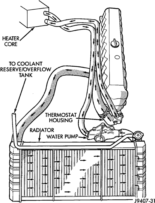
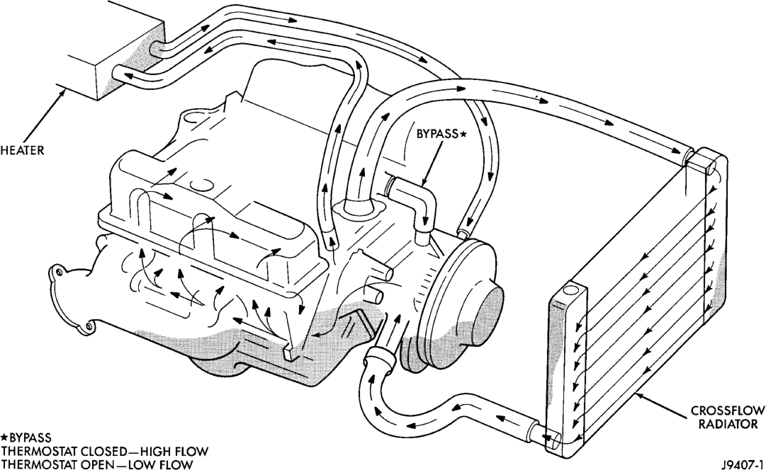
For cooling system flow routings refer to (Fig. 1) (Fig. 2).
RADIATOR
All vehicles are equipped with a cross flow type radiator with plastic side tanks.
Plastic tanks, while stronger than brass, are subject to damage by impact, such as from tools or wrenches. Handle radiator with care.
COOLANT
The cooling system is designed around the coolant. Coolant flows through the engine water jackets absorbing heat produced during engine operation. The coolant carries heat to the radiator and heater core. Here it is transferred to ambient air passing through the radiator and heater core fins. The coolant also removes heat from the automatic transmission fluid in vehicles equipped with an automatic transmission.
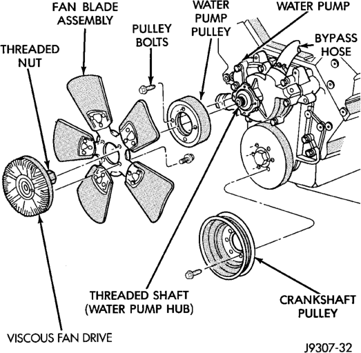
WATER PUMP BYPASS HOSE—5.2L/5.9L V-8 ENGINES
A water pump bypass hose (Fig. 3) is used between the intake manifold and water pump on all 5.2L/5.9L V-8 engines.
ACCESSORY DRIVE BELTS
When installing an accessory drive belt, the belt MUST be routed correctly. If not, the engine may overheat due to water pump rotating in wrong direction. Refer to the appropriate engine Belt Schematic in this group for the correct belt routing, or refer to the Belt Routing Label located in the engine compartment.
BLOCK HEATER
An optional engine block heater is available for all models. The heater is equipped with a power cord. The cord is attached to an engine compartment component with tie-straps. The heater warms the engine providing easier engine starting and faster warm-up in low temperatures. The heater is mounted in a core hole of the engine cylinder block (in place of a freeze plug) with the heating element immersed in engine coolant. Connect the power cord to a grounded 110- 120 volt AC electrical outlet with a grounded, threewire extension cord.
WARNING: DO NOT OPERATE ENGINE UNLESS BLOCK HEATER CORD HAS BEEN DISCONNECTED FROM POWER SOURCE AND SECURED IN PLACE.
DESCRIPTION AND OPERATION
TRANSMISSION OIL COOLER
All models equipped with an automatic transmission are equipped with a transmission oil cooler (water-to-oil) mounted internally within the radiator tank. This internal cooler is supplied as standard equipment on all models equipped with an automatic transmission.
Transmission oil is cooled when it passes through this separate cooler. In case of a leak in the internal radiator mounted transmission oil cooler, engine coolant may become mixed with transmission fluid or transmission fluid may enter the cooling system. Both cooling system and transmission should be drained and inspected if the internal radiator mounted transmission cooler is leaking.
These models do not come equipped with “auxiliary” transmission air-to-oil coolers.
COOLANT RESERVE/OVERFLOW SYSTEM
This system works along with the radiator pressure cap. This is done by using thermal expansion and contraction of the coolant to keep the coolant free of trapped air. It provides:
• A volume for coolant expansion and contraction. • A convenient and safe method for checking/adjusting coolant level at atmospheric pressure. This is done without removing the radiator pressure cap.
• Some reserve coolant to the radiator to cover minor leaks and evaporation or boiling losses.
As the engine cools, a vacuum is formed in the cooling system of both the radiator and engine. Coolant will then be drawn from the coolant tank and returned to a proper level in the radiator.
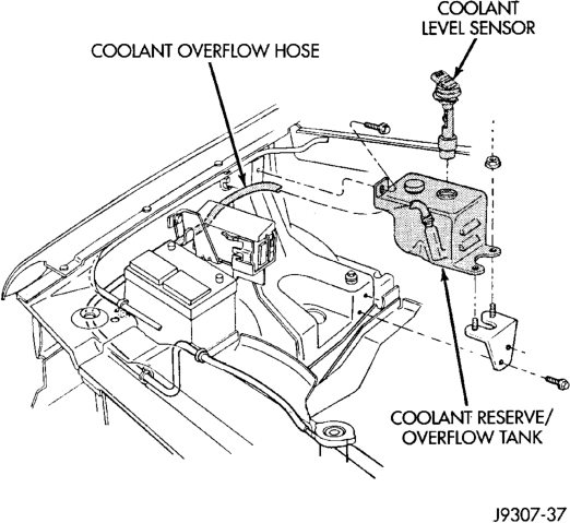
The coolant reserve/overflow system has a radiator mounted pressurized cap, an overflow tube and a plastic coolant reserve/overflow tank (Fig. 4) mounted to the right inner fender.
ACCESSORY DRIVE BELT TENSION
Correct drive belt tension is required to ensure optimum performance of the belt driven engine accessories. If specified tension is not maintained, belt slippage may cause; engine overheating, lack of power steering assist, loss of air conditioning capacity, reduced generator output rate, and greatly reduced belt life.
4.0L ENGINE
Belt tension is adjusted at the power steering pump bracket and idler pulley assembly. There are different types of adjustment gauges for checking either a serpentine or a V-type belt. Refer to the instructions supplied with the gauge. Use the correct gauge when checking belt tension. Place gauge in the middle of the section of belt being tested (between two pulleys) to check tension. Do not allow the gauge (or gauge adapter) to contact anything but the belt.
5.2L/5.9L ENGINES
It is not necessary to adjust belt tension on the 5.2L/5.9L engines. These engines are equipped with an automatic belt tensioner. The tensioner maintains correct belt tension at all times. Due to use of this belt tensioner, do not attempt to use a belt tension gauge on 5.2L/5.9L engines.
BLOCK HEATER
An optional engine block heater (Fig. 5) (Fig. 6)is available with for all models. The heater is equipped with a power cord. The cord is attached to an engine compartment component with tie-straps. The heater warms the engine providing easier engine starting and faster warm-up in low temperatures. The heater is mounted in a core hole of the engine cylinder block in place of a freeze plug with the heating element immersed in engine coolant. Connect power cord to a grounded 110-120 volt AC electrical outlet with a grounded, three wire extension cord.
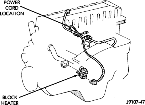
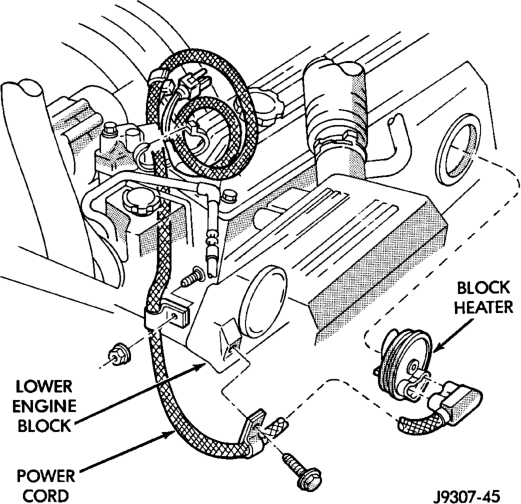
WARNING: DO NOT OPERATE ENGINE UNLESS BLOCK HEATER CORD HAS BEEN DISCONNECTED FROM POWER SOURCE AND SECURED IN PLACE. THE POWER CORD MUST BE SECURED IN ITS RETAINING CLIPS AND ROUTED AWAY FROM EXHAUST MANIFOLDS AND MOVING PARTS.
THERMOSTAT
A pellet-type thermostat controls the operating temperature of the engine by controlling the amount of coolant flow to the radiator. On all engines the thermostat is closed below 195°F (90°C). Above this temperature, coolant is allowed to flow to the radiator. This provides quick engine warm up and overall temperature control.
An arrow, plus the word UP is stamped on the front flange next to the air bleed. The words TO RAD are stamped on one arm of the thermostat. They indicate the proper installed position.
The same thermostat is used for winter and summer seasons. An engine should not be operated without a thermostat, except for servicing or testing. Operating without a thermostat causes other problems. These are: longer engine warmup time, unreliable warmup performance, increased exhaust emissions and crankcase condensation. This condensation can result in sludge formation.
CAUTION: Do not operate an engine without a thermostat, except for servicing or testing.
The more common type of thermostat failure, usually found on high mileage vehicles, is a thermostat failed in the shut position. The temperature gauge (if equipped) will give an indication of this condition. Depending upon length of time that vehicle is operated, pressure cap may vent. This will expel steam and coolant to coolant reserve/overflow tank and to surface below vehicle. Refer to the Diagnosis section of this group.
COOLANT PERFORMANCE
ETHYLENE-GLYCOL MIXTURES
The required ethylene-glycol (antifreeze) and water mixture depends upon the climate and vehicle operating conditions. The recommended mixture of 50/50 ethylene-glycol and water will provide protection against freezing to -37 deg. C (-35 deg. F). The antifreeze concentration must always be a minimum of 44 percent, year-round in all climates. If percentage is lower than 44 percent, engine parts may be eroded by cavitation, and cooling system components may be severely damaged by corrosion. Maximum protection against freezing is provided with a 68 percent antifreeze concentration, which prevents freezing down to -67.7 deg. C (-90 deg. F). A higher percentage will freeze at a warmer temperature. Also, a higher percentage of antifreeze can cause the engine to overheat because the specific heat of antifreeze is lower than that of water.
100 Percent Ethylene-Glycol—Should Not Be Used in Chrysler Vehicles
Use of 100 percent ethylene-glycol will cause formation of additive deposits in the system, as the corrosion inhibitive additives in ethylene-glycol require the presence of water to dissolve. The deposits act as insulation, causing temperatures to rise to as high as 149 deg. C (300) deg. F). This temperature is hot enough to melt plastic and soften solder. The increased temperature can result in engine detonation. In addition, 100 percent ethylene-glycol freezes at 22 deg. C (-8 deg. F ).
Propylene-glycol Formulations—Should Not Be Used in Chrysler Vehicles
Propylene-glycol formulations do not meet Chrysler coolant specifications. It's overall effective temperature range is smaller than that of ethylene-glycol. The freeze point of 50/50 propylene-glycol and water is -32 deg. C (-26 deg. F). 5 deg. C higher than ethylene-glycol's freeze point. The boiling point (protection against summer boil-over) of propyleneglycol is 125 deg. C (257 deg. F ) at 96.5 kPa (14 psi), compared to 128 deg. C (263 deg. F) for ethylene-glycol. Use of propylene-glycol can result in boil-over or freeze-up in Chrysler vehicles, which are designed for ethylene-glycol. Propylene glycol also has poorer heat transfer characteristics than ethylene glycol. This can increase cylinder head temperatures under certain conditions.
Propylene-glycol/Ethylene-glycol Mixtures—Should Not Be Used in Chrysler Vehicles
Propylene-glycol/ethylene-glycol Mixtures can cause the destabilization of various corrosion inhibitors, causing damage to the various cooling system components. Also, once ethylene-glycol and propylene-glycol based coolants are mixed in the vehicle, conventional methods of determining freeze point will not be accurate. Both the refractive index and specific gravity differ between ethylene glycol and propylene glycol.
CAUTION: Richer antifreeze mixtures cannot be measured with normal field equipment and can cause problems associated with 100 percent ethylene-glycol.
COOLANT SELECTION AND ADDITIVES
The presence of aluminum components in the cooling system requires strict corrosion protection. Maintain coolant at specified level with a mixture of ethylene-glycol based antifreeze and water. Chrysler Corporation recommends Mopar Antifreeze or equivalent. If coolant becomes contaminated or looses color, drain and flush cooling system and fill with correctly mixed solution.
A 0.25 percent emulsifiable oil is added to the radiator at the factory to prevent solder corrosion.
CAUTION: Do not use coolant additives that are claimed to improve engine cooling.
RADIATOR PRESSURE CAP
All radiators are equipped with a pressure cap. This cap releases pressure at some point within a range of 97-to-124 kPa (14-to-18 psi). The pressure relief point (in pounds) is engraved on top of the cap (Fig. 7).
The cooling system will operate at pressures slightly above atmospheric pressure. This results in a higher coolant boiling point allowing increased radiator cooling capacity. The cap (Fig. 7) contains a spring-loaded pressure relief valve. This valve opens when system pressure reaches the release range of 97-to-124 kPa (14-to-18 psi).
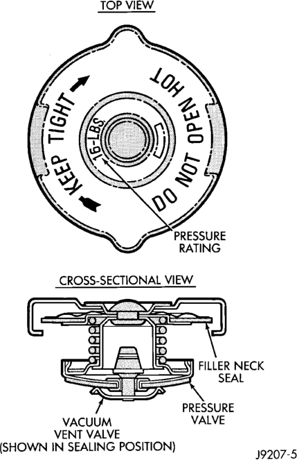
A vent valve in the center of the cap allows a small coolant flow through the cap when coolant is below boiling temperature. The valve is completely closed when boiling point is reached. As the coolant cools, it contracts and creates a vacuum in cooling system. This causes the vacuum valve to open and coolant in reserve/overflow tank to be drawn through connecting hose into radiator. If the vacuum valve is stuck shut, radiator hoses will collapse on cool-down.
A rubber gasket seals the radiator filler neck. This is done to maintain vacuum during coolant cool-down and to prevent leakage when system is under pressure.
WATER PUMP
A centrifugal water pump circulates coolant through the water jackets, passages, intake manifold, radiator core, cooling system hoses and heater core. The pump is driven from the engine crankshaft by a single serpentine drive belt on all engines.
The water pump impeller is pressed onto the rear of a shaft that rotates in bearings pressed into the housing. The housing has two small holes to allow seepage to escape. The water pump seals are lubricated by the antifreeze in the coolant mixture. No additional lubrication is necessary.
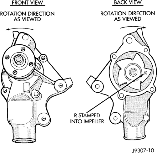
CAUTION: All 4.0L 6-cylinder engines are equipped with a reverse (counterclockwise) rotating water pump and thermal viscous fan drive assembly. REVERSE is stamped or imprinted on the cover of the viscous fan drive and inner side of the fan. The letter R is stamped into the back of the water pump impeller (Fig. 8). Engines from previous model years, depending upon application, may have been equipped with a forward (clockwise) rotating water pump. Installation of the wrong water pump or viscous fan drive will cause engine over heating.
6-Cylinder
A quick test to determine if the pump is working is to check if the heater warms properly. A defective water pump will not be able to circulate heated coolant through the long heater hose to the heater core.
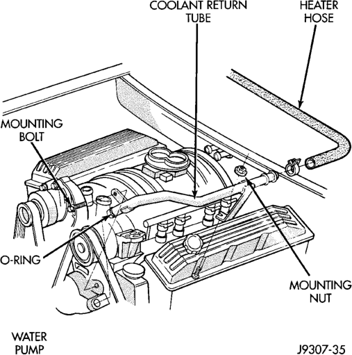
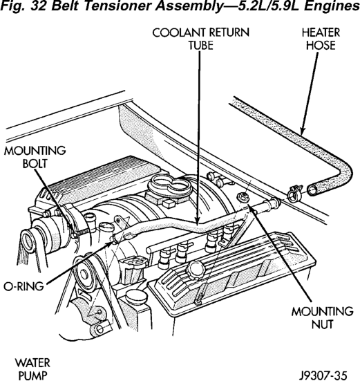
5.2/5.9L ENGINES: One of the heater hoses is connected to the water pump with a metal coolant return tube (Fig. 9). A rubber o-ring forms a seal at the water pump end of the tube.
COOLING SYSTEM HOSES
Rubber hoses route coolant to and from the radiator, intake manifold and heater core. The lower radiator hose is spring-reinforced to prevent collapse from water pump suction at moderate and high engine speeds.
Vehicles equipped with the 5.9L engine and an the “max” cooling package (electric fan) have radiator upper and lower hoses consisting of stainless steel “tees” located between two hoses. The tees house the electric cooling fan low and high speed switches and can only be serviced by replacing the hose assembly.
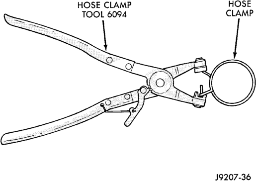
WARNING: CONSTANT TENSION HOSE CLAMPS ARE USED ON MOST COOLING SYSTEM HOSES. WHEN REMOVING OR INSTALLING, USE ONLY TOOLS DESIGNED FOR SERVICING THIS TYPE OF CLAMP, SUCH AS SPECIAL CLAMP TOOL (NUMBER 6094) (Fig. 10). SNAP-ON CLAMP TOOL (NUMBER HPC-20) MAY BE USED FOR LARGER CLAMPS. ALWAYS WEAR SAFETY GLASSES WHEN SERVIC- ING CONSTANT TENSION CLAMPS.
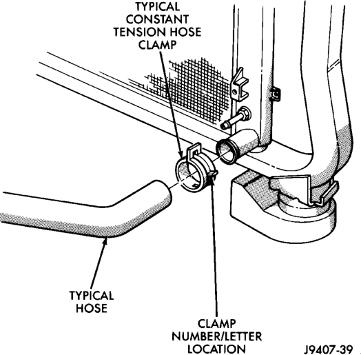
CAUTION: A number or letter is stamped into the tongue of constant tension clamps (Fig. 11). If replacement is necessary, use only an original equipment clamp with matching number or letter.
Inspect the hoses at regular intervals. Replace hoses that are cracked, feel brittle when squeezed, or swell excessively when the system is pressurized.
For all vehicles: In areas where specific routing clamps are not provided, be sure that hoses are positioned with sufficient clearance. Check clearance from exhaust manifolds and pipe, fan blades, drive belts and sway bars. Improperly positioned hoses can be damaged, resulting in coolant loss and engine overheating.
Ordinary worm gear type hose clamps (when equipped) can be removed with a straight screwdriver or a hex socket. To prevent damage to hoses or clamps, the hose clamps should be tightened to 4 N·m (34 in. lbs.) torque. Do not over tighten hose clamps.
When performing a hose inspection, inspect the radiator lower hose for proper position and condition of the internal spring.
ELECTRIC COOLING FAN—5.9L ENGINE
Vehicles equipped with the 5.9L engine recieve a “max” cooling package which consists of a heavy duty radiator and an electric cooling fan. This fan can only be serviced as an assembly.
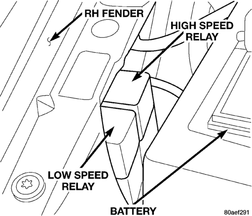
This is a two speed fan (low and high) which is controlled by an ignition relay, low and high speed fan relays (Fig. 12), upper and lower hose coolant temperature switches (Fig. 13) and the A/C highpressure switch. Refer to Group 8W, Wiring Diagrams for the system schematic.
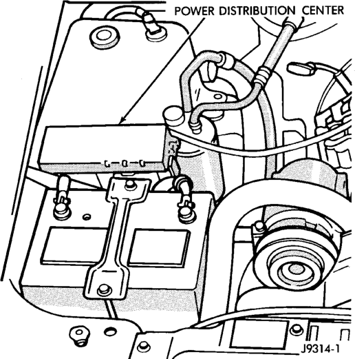
The relays and their control circuits are protected by a 15 amp fuse in the PDC. The electric fan motor and its circuits are protected by a 60 amp “maxifuse” also located in the PDC (Fig. 14). Refer to the inside of the PDC cover for exact fuse position. The cooling fan low and high speed relays are mounted to the passenger inner fender next to the battery (Fig. 12). The relays can be identified by tags on the harness marked “HI” and “LOW”.
CIRCUIT OPERATION The ignition relay provides battery voltage to the low speed fan relay winding when the ignition key is in the start or run position. It also provides battery voltage to the high speed fan relay winding when the key is in the start or run position and the lower hose coolant temperature switch is closed. This relay is located under the Power Distribution Center (PDC), mounted to the PDC bracket.
The low speed cooling fan relay is energized when the ignition key is “on” and the upper hose coolant temperature switch is closed or the A/C is “on” and the high pressure switch closes. This provides battery voltage to the low speed terminal of the cooling fan motor and the cooling fan comes on low speed.
The high speed cooling fan relay is energized when the ignition key is on and the lower hose coolant temperature sensor is closed. This provides battery voltage to the high terminal of the cooling fan motor and the cooling fan comes on high speed.
COOLING FAN OPERATION CHART
COOLANT TEMP
A/C UPPER HOSE SWITCH
LOWER HOSE SWITCH
FAN
-36° - 213°F OFF OPEN OPEN OFF
214° - 219°F OFF CLOSED OPEN ON/LOW
220°F AND UP
OFF CLOSED CLOSED ON/HIGH
-36° - 213°F ON OPEN OPEN ON/LOW
214° - 219°F ON CLOSED OPEN ON/LOW
220°F AND UP
ON CLOSED CLOSED ON/HIGH
WARNING: THE FAN CAN COME ON AT ANY TIME WHEN THE IGNITION KEY IS IN THE (RUN( POSITION.
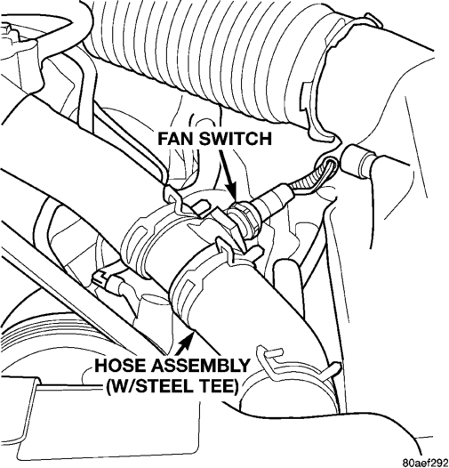
Switch—Typical
VISCOUS FAN DRIVE
The thermal viscous fan drive (Fig. 15) (Fig. 16) is a silicone-fluid-filled coupling used to connect the fan blades to the water pump shaft. The coupling allows the fan to be driven in a normal manner. This is done at low engine speeds while limiting the top speed of the fan to a predetermined maximum level at higher engine speeds.
A thermostatic bimetallic spring coil is located on the front face of the viscous fan drive unit (Fig. 15) (Fig. 16). This spring coil reacts to the temperature of the radiator discharge air. It engages the viscous fan drive for higher fan speed if the air temperature from the radiator rises above a certain point. Until additional engine cooling is necessary, the fan will remain at a reduced rpm regardless of engine speed.
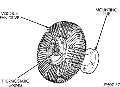
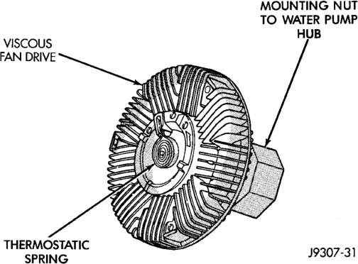
Typical
Only when sufficient heat is present, will the viscous fan drive engage. This is when the air flowing through the radiator core causes a reaction to the bimetallic coil. It then increases fan speed to provide the necessary additional engine cooling.
Once the engine has cooled, the radiator discharge temperature will drop. The bimetallic coil again reacts and the fan speed is reduced to the previous disengaged speed.
CAUTION: Engines equipped with serpentine drive belts have reverse rotating fans and viscous fan drives. They are marked with the word REVERSE to designate their usage. Installation of the wrong fan or viscous fan drive can result in engine overheating.
CAUTION: If the viscous fan drive is replaced because of mechanical damage, the cooling fan blades should also be inspected. Inspect for fatigue cracks, loose blades, or loose rivets that could have resulted from excessive vibration. Replace fan blade assembly if any of these conditions are found. Also inspect water pump bearing and shaft assembly for any related damage due to a viscous fan drive malfunction.
NOISE
NOTE: It is normal for fan noise to be louder (roaring) when:
• The underhood temperature is above the engagement point for the viscous drive coupling. This may occur when ambient (outside air temperature) is very high.
• Engine loads and temperatures are high such as when towing a trailer.
• Cool silicone fluid within the fan drive unit is being redistributed back to its normal disengaged (warm) position. This can occur during the first 15 seconds to one minute after engine start-up on a cold engine.
LEAKS
Viscous fan drive operation is not affected by small oil stains near the drive bearing. If leakage appears excessive, replace the fan drive unit.
DIAGNOSIS AND TESTING
ON-BOARD DIAGNOSTICS (OBD)
COOLING SYSTEM RELATED DIAGNOSTICS
The Powertrain Control Module (PCM) has been programmed to monitor the certain following cooling system components:
• If the engine has remained cool for too long a period, such as with a stuck open thermostat, a Diagnostic Trouble Code (DTC) can be set.
• If an open or shorted condition has developed in the relay circuit controlling the electric radiator fan, a Diagnostic Trouble Code (DTC) can be set.
If the problem is sensed in a monitored circuit often enough to indicate an actual problem, a DTC is stored. The DTC will be stored in the PCM memory for eventual display to the service technician. (Refer to Group 25, Emission Control Systems for proper procedures)
ACCESSING DIAGNOSTIC TROUBLE CODES
To read DTC's and to obtain cooling system data, refer to Group 25, Emission Control Systems for proper procedures.
DRB SCAN TOOL
For operation of the DRB scan tool, refer to the appropriate Powertrain Diagnostic Procedures service manual.
THERMOSTAT
ON-BOARD DIAGNOSTICS
All models are equipped with On-Board Diagnostics for certain cooling system components. Refer to On-Board Diagnostics (OBD) in the Diagnosis section of this group for additional information. If the powertrain control module (PCM) detects low engine coolant temperature, it will record a Diagnostic Trouble Code (DTC) in the PCM memory. Refer to the Diagnosis section of this group for other probable causes. For other DTC numbers, refer to On-Board Diagnostics in Group 25, Emission Control Systems.
The DTC can also be accessed through the DRB scan tool. Refer to the appropriate Powertrain Diagnostic Procedures manual for diagnostic information and operation of the DRB scan tool.
ACCESSORY DRIVE BELT DIAGNOSIS
VISUAL DIAGNOSIS
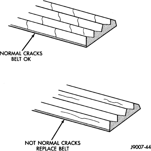
When diagnosing serpentine accessory drive belts, small cracks that run across the ribbed surface of the belt from rib to rib (Fig. 17), are considered normal. These are not a reason to replace the belt. However, cracks running along a rib (not across) are not normal. Any belt with cracks running along a rib must be replaced (Fig. 17). Also replace the belt if it has excessive wear, frayed cords or severe glazing.
Refer to the Accessory Drive Belt Diagnosis charts for further belt diagnosis.
NOISE DIAGNOSIS
Noises generated by the accessory drive belt are most noticeable at idle. Before replacing a belt to resolve a noise condition, inspect all of the accessory drive pulleys for alignment, glazing, or excessive end play.
ACCESSORY DRIVE BELT DIAGNOSIS CHART
RIB CHUNKING (One or more ribs has separated from belt body)
1. Foreign objects imbedded in pulley grooves.
RIB OR BELT WEAR 1. Pulley misaligned 1. Align pulley(s)
BELT SLIPS 1. Belt slipping because of insufficient tension 1. Adjust tension (4.0L). Replace tensioner (5.2L/5.9L Engines)
2. Belt or pulley exposed to substance that has reduced friction (belt dressing, oil, ethylene glycol)
3. Driven component bearing failure (seizure)
LONGITUDAL BELT CRACKING 1. Belt has mistracked from pulley groove
2. Pulley groove tip has worn away rubber to tensile member
9GROOVE JUMPING9 (Belt does not maintain correct position on pulley)
1. Belt tension either too low or too high
2. Pulley(s) not within design tolerance
BELT BROKEN (Note: Identify and correct problem before new belt is installed)
2. Tensile member damaged during belt installation
CONDITION POSSIBLE CAUSES CORRECTION
1. Remove foreign objects from pulley grooves. Replace belt.
2. Installation damage 2. Replace belt
2. Abrasive environment 2. Clean pulley(s). Replace belt if necessary 3. Rusted pulley(s) 3. Clean rust from pulley(s) 4. Sharp or jagged pulley groove tips
4. Replace pulley. Inspect belt.
5. Belt rubber deteriorated 5. Replace belt
2. Replace belt and clean pulleys
3. Replace faulty component or bearing 4. Belt glazed or hardened from heat and excessive slippage
4. Replace belt.
1. Replace belt
2. Replace belt
1. Adjust belt tension (4.0L). Replace tensioner (5.2L/5.9L Engines)
2. Replace pulley(s)
3. Foreign object(s) in grooves 3. Remove foreign objects from grooves 4. Pulley misalignment 4. Align component 5. Belt cordline is broken 5. Replace belt
1. Excessive tension (4.0L) 1. Replace belt and adjust tension to specification
2. Replace belt
3. Severe misalignment 3. Align pulley(s) 4. Bracket, pulley, or bearing failure 4. Replace defective component and belt
NOISE (Objectionable squeal, squeak, or rumble is heard or felt while drive belt is in operation)
5. Locate defective driven component and repair 6. System resonant frequency induced vibration 6. Vary belt tension within specifications. TENSION SHEETING FABRIC FAILURE (Woven fabric on outside, circumference of belt has cracked or separated from body of belt)
1. Tension sheeting contacting stationary object
2. Excessive heat causing woven fabric to age
3. Tension sheeting splice has fractured
CORD EDGE FAILURE (Tensile member exposed at edges of belt or separated from belt body)
PRELIMINARY CHECKS
ENGINE COOLING SYSTEM OVERHEATING
Establish what driving conditions caused the complaint. Abnormal loads on the cooling system such as the following may be the cause.
PROLONGED IDLE, VERY HIGH AMBIENT TEMPERATURE, SLIGHT TAIL WIND AT IDLE, SLOW TRAFFIC, TRAFFIC JAMS, HIGH SPEED, OR STEEP GRADES:
Driving techniques that avoid overheating are: • Idle with A/C off when temperature gauge is at end of normal range.
• Increasing engine speed for more air flow is recommended.
TRAILER TOWING
Consult Trailer Towing section of owners manual. Do not exceed limits.
AIR CONDITIONING; ADD-ON OR AFTER MARKET
These models are equipped with a “heavy duty” cooling system and therefore will accommodate add-on or aftermarket air conditioning. No modifications are necessary to the cooling system.
CONDITION POSSIBLE CAUSES CORRECTION
1. Belt slippage 1. Adjust belt (4.0L). Replace tensioner (5.2L/5.9L Engines)
2. Bearing noise 2. Locate and repair 3. Belt misalignment 3. Align belt/pulley(s) 4. Belt to pulley mismatch 4. Install correct belt 5. Driven component induced vibration
1. Correct rubbing condition
2. Replace belt
3. Replace belt
1. Excessive tension 1. Adjust belt tension (4.0L). Replace tensioner (5.2L/5.9L Engines)
2. Belt contacting stationary object 2. Replace belt 3. Pulley(s) out of tolerance 3. Replace pulley 4. Insufficient adhesion between tensile member and rubber matrix
4. Replace belt and adjust tension to specifications
RECENT SERVICE OR ACCIDENT REPAIR:
Determine if any recent service has been performed on vehicle that may effect cooling system. This may be:
• Engine adjustments (incorrect timing) • Slipping engine accessory drive belt(s) • Brakes (possibly dragging) • Changed parts (incorrect water pump rotating in wrong direction)
• Reconditioned radiator or cooling system refilling (possibly under- filled or air trapped in system).
NOTE: If investigation reveals none of the previous items as a cause for an engine overheating complaint, refer to following Cooling System Diagnosis charts.
COOLING SYSTEM DIAGNOSIS
COOLING SYSTEM DIAGNOSIS CHART
TEMPERATURE GAUGE READS LOW
1. Has a Diagnostic Trouble Code (DTC) been set indicating a stuck open engine thermostat.
2. Is the temperature gauge (if equipped) connected to the temperature gauge coolant sensor on the engine?
TEMPERATURE GAUGE READS HIGH OR ENGINE COOLANT WARNING LAMP ILLUMINATES. COOLANT MAY OR MAY NOT BE LOST OR LEAKING FROM COOLING SYSTEM
1. Trailer is being towed, a steep hill is being climbed, vehicle is operated in slow moving traffic, or engine is being idled with very high ambient (outside) temperatures and the air conditioning is on. Higher altitudes could aggravate these conditions.
2. Is temperature gauge (if equipped) reading correctly?
CONDITION POSSIBLE CAUSES CORRECTION
1. Refer to group 25, Emission Control Systems. Replace thermostat if necessary. If a Diagnostic Trouble Code (DTC) has not been set, the problem may be with the temperature gauge.
2. Check the engine temperature sensor connector in the engine compartment. Refer to Group 8E. Repair as necessary. 3. Is the temperature gauge (if equipped) operating OK?
3. Check gauge operation. Refer to Group 8E. Repair as necessary. 4. Coolant level low in cold ambient temperatures accompanied with poor heater performance.
4. Check coolant level in the coolant reserve/overflow tank and the radiator. Inspect system for leaks. Repair leaks as necessary. Refer to the Coolant section of the manual text for Warnings and precautions before removing the radiator cap. 5. Improper operation of internal heater doors or heater controls.
5. Inspect heater and repair as necessary. Refer to Group 24, Heating and Air Conditioning for procedures.
1. This may be a temporary condition and repair is not necessary. Turn off the air conditioning and attempt to drive the vehicle without any of the previous conditions. Observe the temperature gauge. The gauge should return to the normal range. If the gauge does not return to normal range, determine the cause for overheating and repair. Refer to POSSIBLE CAUSES (numbers 2 through 18).
2. Check gauge. Refer to Group 8E. Repair as necessary. 3. Is temperature warning lamp (if equipped) illuminating unnecessarily?
3. Check warning lamp operation. Refer to Group 8E. Repair as necessary. 4. Coolant low in coolant reserve/ overflow tank and radiator?
4. Check for coolant leaks and repair as necessary. Refer to Testing Cooling System for Leaks in this group.
TEMPERATURE GAUGE READS HIGH OR ENGINE COOLANT WARNING LAMP ILLUMINATES. COOLANT MAY OR MAY NOT BE LOST OR LEAKING FROM COOLING SYSTEM
5. Pressure cap not installed tightly. If cap is loose, boiling point of coolant will be lowered. Also refer to the following step 6.
CONDITION POSSIBLE CAUSES CORRECTION
5. Tighten cap.
6. Poor seals at radiator cap. 6. (a) Check condition of cap and cap seals. Refer to Radiator Cap. Replace cap if necessary. (b) Check condition of radiator filler neck. If neck is bent or damaged, replace radiator. 7. Coolant level low in radiator but not in coolant reserve/overflow tank. This means the radiator is not drawing coolant from the coolant reserve/overflow tank as the engine cools. As the engine cools, a vacuum is formed in the cooling system of the engine and radiator. If radiator cap seals are defective, or cooling system has leaks, a vacuum can not be formed.
7. (a) Check condition of radiator cap and cap seals. Refer to Radiator Cap in this group. Replace cap if necessary. (b) Check condition of radiator filler neck. If neck is bent or damaged, replace radiator. (c) Check the condition of the hose from the radiator to the coolant tank. It should fit tight at both ends without any kinks or tears. Replace hose if necessary. (d) Check coolant reserve/overflow tank and tank hoses for blockage. Repair as necessary 8. Freeze point of antifreeze not correct. Mixture may be too rich.
8. Check antifreeze. Refer to Coolant section of this group. Adjust antifreeze-to-water ratio as required. 9. Coolant not flowing through system.
9. Check for coolant flow at radiator filler neck with some coolant removed, engine warm and thermostat open. Coolant should be observed flowing through radiator. If flow is not observed, determine reason for lack of flow and repair as necessary. 10. Radiator or A/C condenser fins are dirty or clogged.
10. Clean insects or debris. Refer to Radiator Cleaning in this group. 11. Radiator core is corroded or plugged.
11. Have radiator re-cored or replaced. 12. Fuel or ignition system problems.
12. Refer to Fuel and Ignition System groups for diagnosis. Also refer to the appropriate Powertrain Diagnostic Procedures service manual for operation of the DRB scan tool. 13. Dragging brakes. 13. Check and correct as necessary. Refer to Group 5, Brakes in the manual text. 14. Bug screen is being used reducing airflow.
14. Remove bug screen.
TEMPERATURE GAUGE READS HIGH OR ENGINE COOLANT WARNING LAMP ILLUMINATES. COOLANT MAY OR MAY NOT BE LOST OR LEAKING FROM COOLING SYSTEM
15. Thermostat partially or completely shut. This is more prevalent of high mileage vehicles.
16. Thermal viscous fan drive not operating properly.
TEMPERATURE GAUGE READING IS INCONSISTENT (FLUCTUATES, CYCLES OR IS ERRATIC)
1. During cold weather operation, with the heater blower in the high position, the gauge reading may drop slightly.
2. Temperature gauge or engine mounted gauge sensor defective or shorted. Also, corroded or loose wiring in the circuit.
3. Gauge reading rises when vehicle is brought to a stop after heavy use (engine still running).
6. Cylinder head gasket leaking allowing exhaust gas to enter cooling system causing thermostat to open late.
CONDITION POSSIBLE CAUSES CORRECTION
15. Check thermostat operation and replace as necessary. Refer to Thermostats in this group.
16. Check fan drive operation and replace if necessary. Refer to Viscous Fan Drive in this group. 17. Cylinder head gasket leaking. 17. Check for cylinder head gasket leaks. Refer to Testing Cooling System for Leaks in this group. For repair, refer to Group 9, Engines. 18. Heater core leaking. 18. Check heater core for leaks. Refer to Group 24, Heating and Air Conditioning. Repair as necessary.
1. A normal condition. No correction is necessary.
2. Check operation of gauge and repair if necessary. Refer to Group 8E, Instrument Panel and Gauges.
3. A normal condition. No correction is necessary. Gauge reading should return to normal range after vehicle is driven. 4. Gauge reading high after restarting a warmed-up (hot) engine.
4. A normal condition. No correction is necessary. The gauge should return to normal range after a few minutes of engine operation. 5. Coolant level low in radiator (air will build up in the cooling system causing the thermostat to open late).
5. Check and correct coolant leaks. Refer to Testing Cooling System for Leaks in this group.
6. (a) Check for cylinder head gasket leaks with a commercially available Block Leak Tester. Repair as necessary. (b) Check for coolant in the engine oil. Inspect for white steam emitting from exhaust system. Repair as necessary. 7. Water pump impeller loose on shaft.
7. Check water pump and replace as necessary. Refer to Water Pumps in this group. 8. Loose accessory drive belt (water pump slipping).
8. Refer to Engine Accessory Drive Belts in this group. Check and correct as necessary. 9. Air leak on the suction side of water pump allows air to build up in cooling system causing thermostat to open late.
9. Locate leak and repair as necessary.
PRESSURE CAP IS BLOWING OFF STEAM AND/OR COOLANT TO COOLANT TANK. TEMPERATURE GAUGE READING MAY BE ABOVE NORMAL BUT NOT HIGH. COOLANT LEVEL MAY BE HIGH IN COOLANT RESERVE/ OVERFLOW TANK
1. Pressure relief valve in radiator cap is defective.
COOLANT LOSS TO THE GROUND WITHOUT PRESSURE CAP BLOWOFF. GAUGE IS READING HIGH OR HOT
1. Coolant leaks in radiator, cooling system hoses, water pump or engine.
DETONATION OR PRE-IGNITION (NOT CAUSED BY IGNITION SYSTEM). GAUGE MAY OR MAY NOT BE READING HIGH
2. Freeze point of antifreeze not correct. Mixture is too rich or too lean.
HOSE OR HOSES COLLAPSED WHEN ENGINE IS COOLING
1. Vacuum created in cooling system on engine cool-down is not being relieved through coolant reserve/overflow system.
NOISY FAN 1. Fan blades loose. 1. Replace fan blade assembly. Refer to Cooling System Fans in this group.
CONDITION POSSIBLE CAUSES CORRECTION
1. Check condition of radiator cap and cap seals. Refer to Radiator Caps in this group. Replace cap as necessary.
1. Pressure test and repair as necessary. Refer to Testing Cooling System for Leaks in this group.
1. Engine overheating. 1. Check reason for overheating and repair as necessary.
2. Check antifreeze. Refer to the Coolant section of this group. Adjust antifreeze-to-water ratio as required.
1. (a) Radiator cap relief valve stuck. Refer to Radiator Cap in this group. Replace if necessary. (b) Hose between coolant reserve/overflow tank and radiator is kinked. Repair as necessary. (c) Vent at coolant reserve/overflow tank is plugged. Clean vent and repair as necessary. (d) Reserve/overflow tank is interally blocked or plugged. Check for blockage and repair as necessary.
2. Fan blades striking a surrounding object.
2. Locate point of fan blade contact and repair as necessary. 3. Air obstructions at radiator or air conditioning condenser.
3. Remove obstructions and/or clean debris or insects from radiator or A/C condenser. 4. Thermal viscous fan drive has defective bearing.
4. Replace fan drive. Bearing is not serviceable. Refer to Viscous Fan Drive in this group. 5. A certain amount of fan noise (roaring) may be evident from the thermal viscous fan drive. Some of this noise is normal.
5. Refer to Viscous Fan Drive in this group for an explanation of normal fan noise.
INADEQUATE AIR CONDITIONER PERFORMANCE (COOLING SYSTEM SUSPECTED)
2. Thermal viscous fan drive is free-wheeling.
4. Some models with certain engines are equipped with air seals at the radiator and/or A/C condenser. If these seals are missing or damaged, not enough air flow will be pulled through the radiator and A/C condenser.
INADEQUATE HEATER PERFORMANCE. THERMOSTAT FAILED IN OPEN POSITION
1. Has a diagnostic trouble code (DTC) been set?
HEAT ODOR 1. Various heat shields are used at certain drive line components. One or more of these shields may be missing.
2. Is temperature gauge reading above the normal range?
CONDITION POSSIBLE CAUSES CORRECTION
1. Radiator and/or A/C condenser is restricted, obstructed or dirty (insects, leaves etc.)
1. Remove restriction and/or clean as necessary. Refer to Radiator Cleaning in this group.
2. Refer to Viscous Fan Drive for diagnosis. Repair as necessary. 3. Engine is overheating (heat may be transferred from radiator to A/C condenser. High underhood temperatures due to engine overheating may also transfer heat to A/C components).
3. Correct overheating condition. Refer to text in Group 7, Cooling.
4. Check for missing or damaged air seals and repair as necessary.
1. Refer to group 25, Emission Control System and replace thermostat if necessary.
2. Coolant level low. 2. Refer to Testing Cooling System for Leaks in the manual text. Repair as necessary. 3. Obstructions in heater hose fittings at engine.
3. Remove heater hoses at both ends and check for obstructions. Repair as necessary. 4. Heater hose kinked. 4. Locate kinked area and repair as necessary. 5. Water pump is not pumping water to heater core. When the engine is fully warmed up, both heater hoses should be hot to the touch. If only one of the hoses is hot, the water pump may not be operating correctly. The accessory drive belt may also be slipping causing poor water pump operation.
5. Refer to Water Pumps in this group. Repair as necessary. If a slipping belt is detected, refer to Engine Accessory Drive Belts in this group. Repair as necessary.
1. Locate missing shields and replace or repair as necessary.
2. Refer to the previous Temperature Gauge Reads High in these Diagnosis Charts. Repair as necessary.
HEAT ODOR 3. Is cooling fan operating correctly. 3. Refer to Cooling System Fan in this group for diagnosis. Repair as necessary
4. Has undercoating been applied to any unnecessary component.
5. Engine may be running rich causing the catalytic converter to overheat.
POOR DRIVEABILITY (THERMOSTAT POSSIBLY STUCK OPEN). GAUGE MAY BE READING LOW
STEAM IS COMING FROM FRONT OF VEHICLE NEAR GRILL AREA WHEN WEATHER IS WET, ENGINE IS WARMED UP AND RUNNING, AND VEHICLE IS STATIONARY. TEMPERATURE GAUGE IS IN NORMAL RANGE
COOLANT COLOR 1. Coolant color is not necessarily an indication of adequate corrosion or temperature protection. Do not rely on coolant color for determining condition of coolant.
COOLANT LEVEL CHANGES IN COOLANT RESERVE/OVERFLOW TANK. TEMPERATURE GAUGE IS IN NORMAL RANGE
1. Level changes are to be expected as coolant volume fluctuates with engine temperature. If the level in the tank was between the FULL and ADD marks at normal engine operating temperature, the level should return to within that range after operation at elevated temperatures.
CONDITION POSSIBLE CAUSES CORRECTION
4. Clean undercoating as necessary.
5. Refer to the DRB scan tool and the appropriate Powertrain Diagnostic Procedures service manual. Repair as necessary.
1. For proper driveability, good vehicle emissions and for preventing build-up of engine oil sludge, the thermostat must be operating properly. Has a diagnostic trouble code (DTC) been set?
1. Refer to group 25, Emission Control System. DTC's may also be checked using the DRB scan tool. Refer to the proper Powertrain Diagnostics Procedures service manual for checking the thermostat using the DRB scan tool. Replace thermostat if necessary.
1. During wet weather, moisture (snow, ice or rain condensation) on the radiator will evaporate when the thermostat opens. This opening allows heated water into the radiator. When the moisture contacts the hot radiator, steam may be emitted. This usually occurs in cold weather with no fan or airflow to blow it away.
1. Occasional steam emitting from this area is normal. No repair is necessary.
1. Refer to Coolant in this group for antifreeze tests. Adjust antifreeze-towater ratio as necessary.
1. A normal condition. No repair is necessary.
RADIATOR COOLANT FLOW CHECK
The following procedure will determine if coolant is flowing through the cooling system.
If engine is cold, idle engine until normal operating temperature is reached. Then feel the upper radiator hose. If hose is hot, the thermostat is open and water is circulating through cooling system.
COOLING SYSTEM—TESTING FOR LEAKS
ULTRAVIOLET LIGHT METHOD
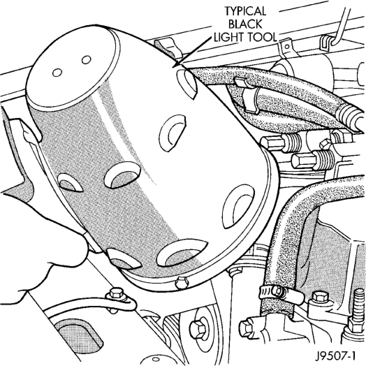
All Jeep models have a leak detection additive added to the cooling system before they leave the factory. The additive is highly visible under ultraviolet light (black light). If the factory original coolant has been drained, pour one ounce of additive into the cooling system. The additive is available through the parts department. Place the heater control unit in HEAT position. Start and operate the engine until the radiator upper hose is warm to the touch. Aim the commercially available black light tool at the components to be checked. If leaks are present, the black light will cause the additive to glow a bright green color.
The black light can be used along with a pressure tester to determine if any external leaks exist (Fig. 18).
PRESSURE TESTER METHOD
The engine should be at the normal operating temperature. Recheck the system cold if the cause of coolant loss is not located during warm engine examination.
WARNING: HOT, PRESSURIZED COOLANT CAN CAUSE INJURY BY SCALDING.
Carefully remove the radiator pressure cap from the filler neck and check the coolant level. Push down on the cap to disengage it from the stop tabs. Wipe the inner part of the filler neck and examine the lower inside sealing seat for nicks, cracks, paint, dirt and solder residue. Inspect the reserve/overflow tank tube for internal obstructions. Insert a wire through the tube to be sure it is not obstructed.
Inspect the cams on the outside part of the filler neck. If the cams are bent, seating of pressure cap valve and tester seal will be affected. Replace cap if cams are bent.
Attach pressure tester 7700 (or an equivalent) to the radiator filler neck (Fig. 19).
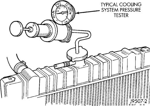
Operate the tester pump to apply 124 kPa (18 psi) pressure to the system. If the hoses enlarge excessively or bulge while testing, replace as necessary. Observe the gauge pointer and determine the condition of the cooling system according to the following criteria:
• Holds Steady: If the pointer remains steady for two minutes, there are no serious coolant leaks in the system. However, there could be an internal leak that does not appear with normal system test pressure. Inspect for interior leakage or do the Internal Leakage Test. Do this if it is certain that coolant is being lost and no leaks can be detected.
• Drops Slowly: Shows a small leak or seepage is occurring. Examine all connections for seepage or slight leakage with a flashlight. Inspect the radiator, hoses, gasket edges and heater. Seal any small leak holes with a Sealer Lubricant or equivalent. Repair leak holes and reinspect the system with pressure applied.
• Drops Quickly: Shows that a serious leakage is occurring. Examine the system for serious external leakage. If no leaks are visible, inspect for internal leakage. Large radiator leak holes should be repaired by a reputable radiator repair shop.
INTERNAL LEAKAGE INSPECTION
Remove the oil pan drain plug and drain a small amount of engine oil. Coolant, being heavier, will drain first, or operate engine to churn oil, then examine dipstick for water globules. Inspect the transmission dipstick for water globules. Inspect the transmission fluid cooler for leakage. Operate the engine without the pressure cap on the radiator until thermostat opens.
Attach a Pressure Tester to the filler neck. If pressure builds up quickly, a leak exists as result of a faulty cylinder head gasket or crack in the engine. Repair as necessary.
WARNING: DO NOT ALLOW PRESSURE TO EXCEED 124 KPA (18 PSI). TURN THE ENGINE OFF. TO RELEASE THE PRESSURE, ROCK THE TESTER FROM SIDE TO SIDE. WHEN REMOVING THE TESTER, DO NOT TURN THE TESTER MORE THAN 1/2 TURN IF THE SYSTEM IS UNDER PRESSURE.
If there is no immediate pressure increase, pump the Pressure Tester until the indicated pressure is within the system range. Vibration of the gauge pointer indicates compression or combustion leakage into the cooling system.
WARNING: DO NOT DISCONNECT THE SPARK PLUG WIRES WHILE THE ENGINE IS OPERATING.
CAUTION: Do not operate the engine with a spark plug shorted for more than a minute. The catalytic converter may be damaged.
Isolate the compression leak by shorting each spark plug to the cylinder block. The gauge pointer should stop or decrease vibration when spark plug for leaking cylinder is shorted. This happens because of the absence of combustion pressure.
COMBUSTION LEAKAGE TEST (WITHOUT
PRESSURE TESTER)
DO NOT WASTE reusable coolant. If the solution is clean, drain the coolant into a clean container for reuse.
WARNING: DO NOT REMOVE THE CYLINDER BLOCK DRAIN PLUGS OR LOOSEN THE RADIATOR DRAINCOCK WITH THE SYSTEM HOT AND UNDER PRESSURE. SERIOUS BURNS FROM COOLANT CAN OCCUR.
Drain sufficient coolant to allow for thermostat removal. Refer to Thermostat Replacement. Disconnect the water pump drive belt.
Disconnect the upper radiator hose from the thermostat housing. Remove the housing and thermostat. Install the thermostat housing.
Add coolant to the radiator to bring the level to within 6.3 mm (1/4 in) of the top of the thermostat housing.
CAUTION: Avoid overheating. Do not operate the engine for an excessive period of time. Open the draincock immediately after the test to eliminate boil over of coolant.
Start the engine and accelerate rapidly three times (to approximately 3000 rpm) while observing the coolant. If internal engine combustion gases are leaking into the cooling system, bubbles will appear in the coolant. If bubbles do not appear, there is no internal combustion gas leakage.
VISCOUS FAN DRIVE
TESTING
If the fan assembly free-wheels without drag (the fan blades will revolve more than five turns when spun by hand), replace the fan drive. This spin test must be performed when the engine is cool.
For the following test, the cooling system must be in good condition. It also will ensure against excessively high coolant temperature.
WARNING: BE SURE THAT THERE IS ADEQUATE FAN BLADE CLEARANCE BEFORE DRILLING.
(1) Drill a 3.18-mm (1/8-in) diameter hole in the top center of the fan shroud.
(2) Obtain a dial thermometer with an 8 inch stem (or equivalent). It should have a range of -18° to 105°C (0° to 220° F). Insert thermometer through the hole in the shroud. Be sure that there is adequate clearance from the fan blades.
(3) Connect a tachometer and an engine ignition timing light (timing light is to be used as a strobe light).
(4) Block the air flow through the radiator. Secure a sheet of plastic in front of the radiator (or air conditioner condenser). Use tape at the top to secure the plastic and be sure that the air flow is blocked.
(5) Be sure that the air conditioner (if equipped) is turned off.
WARNING: USE EXTREME CAUTION WHEN THE ENGINE IS OPERATING. DO NOT STAND IN A DIRECT LINE WITH THE FAN. DO NOT PUT YOUR HANDS NEAR THE PULLEYS, BELTS OR FAN. DO NOT WEAR LOOSE CLOTHING.
(6) Start the engine and operate at 2400 rpm. Within ten minutes the air temperature (indicated on the dial thermometer) should be up to 88° C (190° F). Fan drive engagement should have started to occur at between 74° to 82° C (165° to 180° F). Engagement is distinguishable by a definite increase in fan flow noise (roaring). The timing light also will indicate an increase in the speed of the fan.
(7) When the air temperature reaches 88° C (190° F), remove the plastic sheet. Fan drive disengagement should have started to occur at between 57° to 79° C (135° to 175° F). A definite decrease of fan flow noise (roaring) should be noticed. If not, replace the defective viscous fan drive unit.
RADIATOR CAP TO FILLER NECK SEAL— PRESSURE RELIEF CHECK
With radiator cap installed on filler neck, remove coolant reserve/overflow tank hose from nipple on filler neck. Connect a hand operated vacuum pump to nipple. Operate pump until a reading of 47 to 61 kPa (14 to 18 in. Hg) appears on gauge. If the reading stays steady, or drops slightly and then remains steady, the pressure valve seal is good. Replace radiator cap if reading does not hold.
WARNING: THE WARNING WORDS —DO NOT OPEN HOT— ON THE RADIATOR PRESSURE CAP ARE A SAFETY PRECAUTION. WHEN HOT, PRES- SURE BUILDS UP IN COOLING SYSTEM. TO PRE- VENT SCALDING OR INJURY, THE RADIATOR CAP SHOULD NOT BE REMOVED WHILE THE SYSTEM IS HOT AND/OR UNDER PRESSURE.
There is no need to remove the radiator cap except for the following purposes:
• To check and adjust antifreeze freeze point. • To refill system with new antifreeze. • For conducting service procedures. • When checking for vacuum leaks.
WARNING: IF VEHICLE HAS BEEN RUN RECENTLY, WAIT AT LEAST 15 MINUTES BEFORE REMOVING RADIATOR CAP. WITH A RAG, SQUEEZE RADIATOR UPPER HOSE TO CHECK IF SYSTEM IS UNDER PRESSURE. PLACE A RAG OVER THE CAP AND WITHOUT PUSHING DOWN, ROTATE CAP COUNTER-CLOCKWISE TO THE FIRST STOP. ALLOW FLUID TO ESCAPE THROUGH OVERFLOW HOSE INTO COOLANT RESERVE/ OVERFLOW TANK. SQUEEZE RADIATOR UPPER
HOSE TO DETERMINE WHEN PRESSURE HAS BEEN RELEASED. WHEN COOLANT AND STEAM STOP BEING PUSHED INTO TANK AND SYSTEM PRESSURE DROPS, REMOVE RADIATOR CAP COMPLETELY.
RADIATOR CAP—PRESSURE TESTING
Remove cap from radiator. Be sure that sealing surfaces are clean. Moisten rubber gasket with water and install the cap on pressure tester (tool 7700 or an equivalent) (Fig. 20).
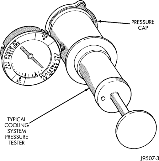

Operate the tester pump and observe the gauge pointer at its highest point. The cap release pressure should be 97 to 124 kPa (14 to 18 psi). The cap is satisfactory when the pressure holds steady. It is also good if it holds pressure within the 97 to 124 kPa (14 to 18 psi) range for 30 seconds or more. If the pointer drops quickly, replace the cap.
CAUTION: Radiator pressure testing tools are very sensitive to small air leaks, which will not cause cooling system problems. A pressure cap that does not have a history of coolant loss should not be replaced just because it leaks slowly when tested with this tool. Add water to tool. Turn tool upside down and recheck pressure cap to confirm that cap needs replacement.
LOW COOLANT LEVEL-AERATION
If the coolant level in radiator drops below top of radiator core tubes, air will enter cooling system.
Low coolant level can cause thermostat pellet to be suspended in air instead of coolant. This will cause thermostat to open later, which in turn causes higher coolant temperature. Air trapped in cooling system also reduces amount of coolant circulating in heater core resulting in low heat output.
DEAERATION
As the engine operates, any air trapped in cooling system gathers under the radiator cap. The next time the engine is operated, thermal expansion of coolant will push any trapped air past radiator cap into the coolant reserve/overflow tank. Here it escapes to the atmosphere into the tank. When the engine cools down the coolant, it will be drawn from the reserve/ overflow tank into the radiator to replace any removed air.
SERVICE PROCEDURES
COOLANT LEVEL—ROUTINE CHECK
NOTE: Do not remove radiator cap for routine coolant level inspections. The coolant level can be checked at coolant reserve/overflow tank.
The coolant reserve/overflow system provides a quick visual method for determining coolant level without removing radiator pressure cap. With engine idling and at normal operating temperature, observe coolant level in reserve/overflow tank. The coolant level should be between ADD and FULL marks.
COOLANT—ADDING ADDITIONAL
Do not remove radiator cap to add coolant to system. When adding coolant to maintain correct level, do so at coolant reserve/overflow tank. Use a 50/50 mixture of ethylene-glycol antifreeze and low mineral content water. Remove radiator cap only for testing or when refilling system after service. Removing cap unnecessarily can cause loss of coolant and allow air to enter system, which produces corrosion.
SERVICE COOLANT LEVEL
The cooling system is closed and designed to maintain coolant level to top of radiator.
WARNING: DO NOT OPEN RADIATOR DRAINCOCK WITH ENGINE RUNNING OR WHILE ENGINE IS HOT AND COOLING SYSTEM IS UNDER PRESSURE.
When vehicle servicing requires a coolant level check in radiator, drain several ounces of coolant from radiator drain cock. Do this while observing coolant reserve/overflow system tank. The coolant level in reserve/overflow tank should drop slightly. If not, inspect for a leak between radiator and coolant reserve/overflow system connection. Remove radiator cap. The coolant level should be to top of radiator. If not and if coolant level in reserve/overflow tank is at ADD mark, check for:
• An air leak in coolant reserve/overflow tank or its hose • An air leak in radiator filler neck • Leak in pressure cap seal to radiator filler neck
COOLING SYSTEM—DRAINING AND FILLING
DRAINING COOLING SYSTEM
WARNING: DO NOT REMOVE THE CYLINDER BLOCK DRAIN PLUGS OR LOOSEN THE RADIATOR DRAINCOCK WITH SYSTEM HOT AND UNDER PRESSURE. SERIOUS BURNS FROM COOLANT CAN OCCUR.
DO NOT WASTE reusable coolant. If the solution is clean, drain the coolant into a clean container for reuse.
DRAINING ENTIRE SYSTEM
Use this procedure if the entire cooling system is to be drained, such as for engine removal.
(1) DO NOT remove radiator cap first. With engine cold, raise vehicle on a hoist and locate radiator draincock.
• 4.0L 6-cyl. Engine: Radiator draincock is located on the right/lower side of radiator facing to rear of vehicle.
• 5.2/5.9L V-8 Engines: Radiator draincock is located on the left/lower side of radiator facing to rear of vehicle.
(2) Attach one end of a hose to the draincock. Put the other end into a clean container. Open draincock and drain coolant from radiator. This will empty the coolant reserve/overflow tank. The coolant does not have to be removed from the tank unless the system is being refilled with a fresh mixture. When tank is empty, remove radiator cap and continue draining cooling system.
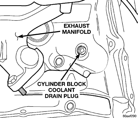
To drain the 4.0L 6-cylinder engine of coolant, remove the cylinder block drain plug located on the side of cylinder block (Fig. 21).
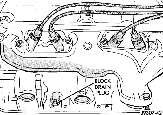
To drain the 5.2/5.9L V-8 engines of coolant, remove the cylinder block drain plugs located on the sides of cylinder block above the oil pan rail (Fig. 22).
PARTIAL DRAINING
Engines
Use this procedure if the coolant is to be partially drained, such as for engine thermostat removal.
(1) With engine cold, slowly remove the radiator cap. Raise vehicle on a hoist and locate radiator draincock.
• 4.0L Engine: Radiator draincock is located on the right/lower side of radiator facing to rear of vehicle.
• 5.2/5.9L Engines: Radiator draincock is located on the left/lower side of radiator facing to rear of vehicle.
(2) Attach one end of a hose to the draincock. Put the other end into a clean container.
(3) Open draincock and drain desired amount of coolant from radiator.
REFILLING COOLING SYSTEM
(1) Tighten the radiator draincock and the cylinder block drain plug(s) (if removed).
(2) Fill system using a 50/50 mixture of ethyleneglycol anifreeze and low mineral conent water. Fill radiator to top and install radiator cap. Add sufficient coolant to the reserve/overflow tank to raise level to FULL mark.
(3) With heater control unit in the HEAT position, operate engine with radiator cap in place.
(4) After engine has reached normal operating temperature, shut engine off and allow it to cool. When engine is cooling down, coolant will be drawn into the radiator from the reserve/overflow tank. (5) Add coolant to reserve/overflow tank as necessary. Only add coolant to the reserve/overflow tank when the engine is cold. Coolant level in a warm engine will be higher due to thermal expansion. To purge the cooling system of all air, this heat up/cool down cycle (adding coolant to cold engine) must be performed three times. Add necessary coolant to raise tank level to the FULL mark after each cool down period.
COOLING SYSTEM—REVERSE FLUSHING
CAUTION: The cooling system normally operates at 97 to 124 kPa (14 to 18 psi) pressure. Exceeding this pressure may damage the radiator or hoses.
CHEMICAL CLEANING
In some instances, use a radiator cleaner (Mopar Radiator Kleen or equivalent) before flushing. This will soften scale and other deposits and aid the flushing operation.
CAUTION: Be sure instructions on the container are followed.
REVERSE FLUSHING
Reverse flushing of the cooling system is the forcing of water through the cooling system. This is done using air pressure in the opposite direction of normal coolant flow. It is usually only necessary with very dirty systems with evidence of partial plugging.
REVERSE FLUSHING RADIATOR
Disconnect the radiator hoses from the radiator fittings. Attach a section of radiator hose to the radiator bottom outlet fitting and insert the flushing gun. Connect a water supply hose and air supply hose to the flushing gun.
CAUTION: The cooling system normally operates at 97 to 124 kPa (14 to 18 psi) pressure. Exceeding this pressure may damage the radiator or hoses.
Allow the radiator to fill with water. When radiator is filled, apply air in short blasts allowing radiator to refill between blasts. Continue this reverse flushing until clean water flows out through rear of radiator cooling tube passages. For more information, refer to operating instructions supplied with flushing equipment. Have radiator cleaned more extensively by a radiator repair shop.
REVERSE FLUSHING ENGINE
Drain the cooling system. Remove the thermostat housing and thermostat. Install the thermostat housing. Disconnect the radiator upper hose from the radiator and attach the flushing gun to the hose. Disconnect the radiator lower hose from the water pump. Attach a lead away hose to the water pump inlet fitting. Connect the water supply hose and air supply hose to the flushing gun. Allow the engine to fill with water. When the engine is filled, apply air in short blasts, allowing the system to fill between air blasts. Continue until clean water flows through the lead away hose. For more information, refer to operating instructions supplied with flushing equipment. Remove the lead away hose, flushing gun, water supply hose and air supply hose. Remove the thermostat housing and install thermostat. Install the thermostat housing with a replacement gasket. Refer to Thermostat Replacement. Connect the radiator hoses. Refill the cooling system with the correct antifreeze/water mixture.
REMOVAL AND INSTALLATION
AUTOMATIC TRANSMISSION OIL COOLER
The internal transmission oil cooler located within the radiator is not serviceable. If it requires service, the radiator must be replaced.
Once the repaired or replacement radiator has been installed, fill the cooling system and inspect for leaks. Refer to the Filling Cooling System and Testing Cooling System For Leaks sections in this group. If the transmission operates properly after repairing the leak, drain the transmission and remove the transmission oil pan. Inspect for sludge. Inspect for a dirty or plugged inlet filter. If none of these conditions are found, the transmission and torque converter may require reconditioning. Refer to Group 21 for automatic transmission servicing.
WATER PUMP—4.0L ENGINE
CAUTION: If the water pump is replaced because of mechanical damage, the fan blades and viscous fan drive should also be inspected. These components could have been damaged due to excessive vibration.
REMOVAL
The water pump can be removed without discharging the air conditioning system (if equipped).
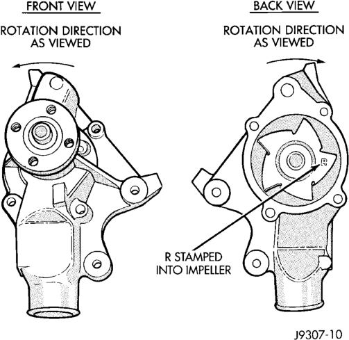
CAUTION: The 4.0L engine has a reverse (counterclockwise) rotating water pump. The letter R is stamped into the back of the water pump impeller (Fig. 23) to identify. Engines from previous model years, depending upon application, may be equipped with a forward (clockwise) rotating water pump. Installation of the wrong water pump will cause engine over heating.
The water pump impeller is pressed on the rear of the pump shaft and bearing assembly. The water pump is serviced only as a complete assembly.
WARNING: DO NOT REMOVE THE BLOCK DRAIN PLUG(S) OR LOOSEN RADIATOR DRAINCOCK WITH THE SYSTEM HOT AND UNDER PRESSURE. SERIOUS BURNS FROM COOLANT CAN OCCUR.
DO NOT WASTE reusable coolant. If the solution is clean, drain coolant into a clean container for reuse.
(1) Disconnect negative battery cable at battery. (2) Drain the cooling system. (3)
Vehicles with 4.0L 6-cylinder engine equipped with A/C or heavy duty cooling system:
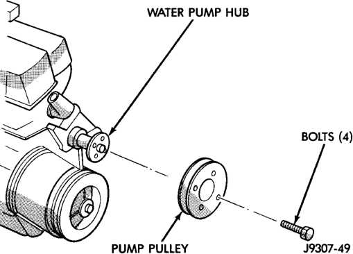
(4) Loosen (but do not remove at this time) the four water pump pulley-to-water pump hub mounting bolts (Fig. 24).
(5) Vehicles with 4.0L 6-cylinder engine without A/C or heavy duty cooling system:
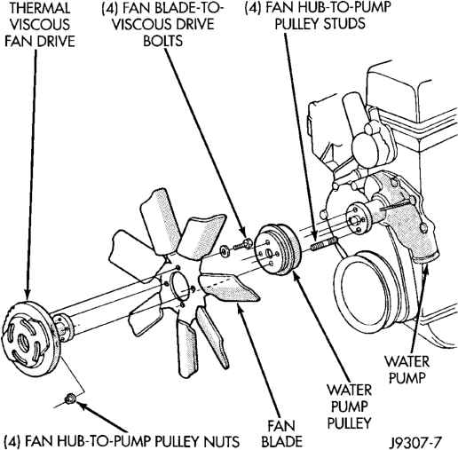
(6) Loosen (but do not remove at this time) the four fan hub-to-water pump pulley mounting nuts (Fig. 25).
NOTE: The engine accessory drive belt must be removed prior to removing the fan (if installed at pump) or fan pulley.
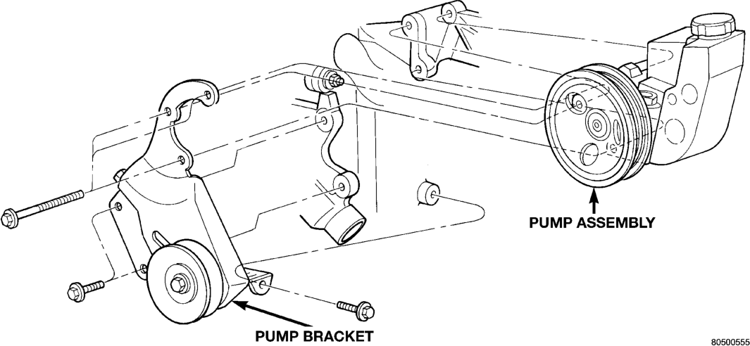
(7) Remove engine drive belt. (8) Remove power steering pump (Fig. 26), refer to Group 19 Steering.
Fig. 26 Power Steering Pump Attachment
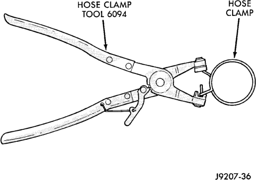
WARNING: CONSTANT TENSION HOSE CLAMPS ARE USED ON MOST COOLING SYSTEM HOSES. WHEN REMOVING OR INSTALLING, USE ONLY TOOLS DESIGNED FOR SERVICING THIS TYPE OF CLAMP, SUCH AS SPECIAL CLAMP TOOL (NUMBER 6094) (Fig. 27) SNAP-ON CLAMP TOOL (NUMBER HPC-20) MAY BE USED FOR LARGER CLAMPS. ALWAYS WEAR SAFETY GLASSES WHEN SERVIC- ING CONSTANT TENSION CLAMPS.
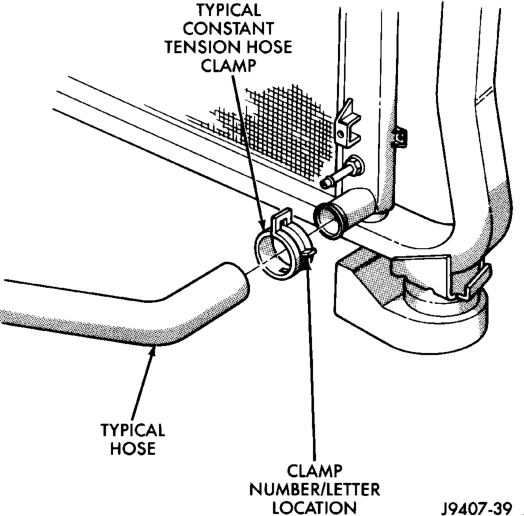
CAUTION: A number or letter is stamped into the tongue of constant tension clamps (Fig. 28). If replacement is necessary, use only an original equipment clamp with matching number or letter.
(9) Remove lower radiator hose from water pump. Remove heater hose from water pump fitting.
(10) Remove four nuts or bolts previously loosened and remove the fan blade assembly and pulley (if fan is installed at pump), or remove the pulley from the vehicle.
(11) After removing fan blade/viscous fan drive assembly, do not place thermal viscous fan drive in horizontal position. If stored horizontally, silicone fluid in viscous fan drive could drain into its bearing assembly and contaminate lubricant.
(12) Remove the four pump mounting bolts (Fig. 29) and remove pump from vehicle. Discard old gasket. Note that one of the four bolts is longer than the other bolts.
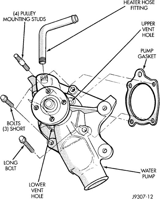
(13) If pump is to be replaced, the heater hose fitting must be removed. Note position of fitting before removal.
INSTALLATION
(1) If pump is being replaced, install the heater hose fitting to the pump. Use a sealant on the fitting such as Mopary Thread Sealant With Teflon. Refer to the directions on the package.
(2) Clean the gasket mating surfaces. If the original pump is used, remove any deposits or other foreign material. Inspect the cylinder block and water pump mating surfaces for erosion or damage from cavitation.
(3) Install the gasket and water pump. The silicone bead on the gasket should be facing the water pump. Also, the gasket is installed dry. Tighten mounting bolts to 30 N·m (22 ft. lbs.) torque. Rotate the shaft by hand to be sure it turns freely.
(4) Connect the radiator and heater hoses to the water pump.
(5) Position water pump pulley to water pump hub.
(6) If equipped with a water pump mounted fan, install fan and four nuts to water pump hub. If not equipped with a water pump mounted fan, install four pump hub bolts. Tighten bolts (or nuts) to 27 N·m (20 ft. lbs.) torque.
(7) Install power steering pump.
CAUTION: When installing the serpentine engine accessory drive belt, the belt MUST be routed correctly. If not, the engine may overheat due to the water pump rotating in the wrong direction. Refer to the Belt Removal and Installtion in this group for appropriate belt routing. You may also refer to the Belt Routing Label in the vehicle engine compartment.
(8) Adjust accessory drive belt, refer to Accessory Drive Belt removal and installation in this group.
(9) Fill cooling system with coolant and check for leaks. Refer to Refilling Cooling System in this group.
(10) Connect battery cable to battery. (11) Start and warm the engine. Check for leaks.
WATER PUMP—5.2L/5.9L ENGINES
The water pump on 5.2L/5.9L engines is bolted directly to the engine timing chain case/cover.
A gasket is used as a seal between the water pump and timing chain case/cover.
If water pump is replaced because of bearing/shaft damage, or leaking shaft seal, the mechanical cooling fan assembly should also be inspected. Inspect for fatigue cracks, loose blades, or loose rivets that could have resulted from excessive vibration. Replace fan if any of these conditions are found. Also check condition of the thermal viscous fan drive. Refer to Viscous Fan Drive in this group.
The water pump can be removed without discharging the air conditioning system (if equipped).
REMOVAL
(1) Disconnect negative battery cable from battery. (2) Drain cooling system. Refer to Draining Cooling System in this group. Do not waste reusable coolant. If solution is clean, drain coolant into a clean container for reuse.
(3) The thermal viscous fan drive is attached (threaded) to the water pump hub shaft (Fig. 30). Remove fan/viscous fan drive assembly from water pump by turning mounting nut counterclockwise as viewed from front. Threads on viscous fan drive are RIGHT HAND. A Snap-On 36 MM Fan Wrench (number SP346 from Snap-On Cummins Diesel Tool Set number 2017DSP) can be used. Place a bar or screwdriver between water pump pulley bolts (Fig. 30) to prevent pulley from rotating. Do not attempt to remove fan/viscous fan drive assembly from vehicle at this time.
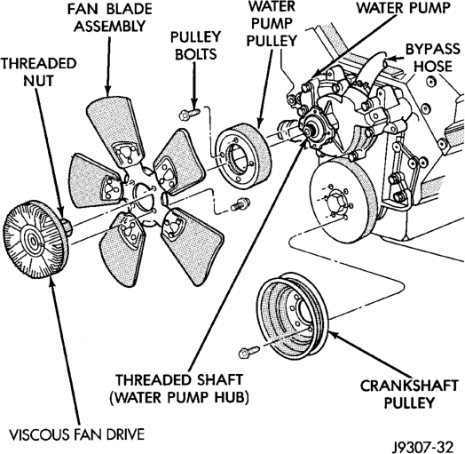
Engines
WARNING: CONSTANT TENSION HOSE CLAMPS ARE USED ON MOST COOLING SYSTEM HOSES. WHEN REMOVING OR INSTALLING, USE ONLY TOOLS DESIGNED FOR SERVICING THIS TYPE OF CLAMP, SUCH AS SPECIAL CLAMP TOOL (NUMBER 6094) (Fig. 27). SNAP-ON CLAMP TOOL (NUMBER HPC-20) MAY BE USED FOR LARGER CLAMPS. ALWAYS WEAR SAFETY GLASSES WHEN SERVIC- ING CONSTANT TENSION CLAMPS.
CAUTION: A number or letter is stamped into the tongue of constant tension clamps (Fig. 28). If replacement is necessary, use only an original equipment clamp with matching number or letter.
(4) If water pump is being replaced, do not unbolt fan blade assembly (Fig. 30) from thermal viscous fan drive.
(5) Remove two fan shroud-to-radiator nuts (Fig. 31). Do not attempt to remove fan shroud at this time.
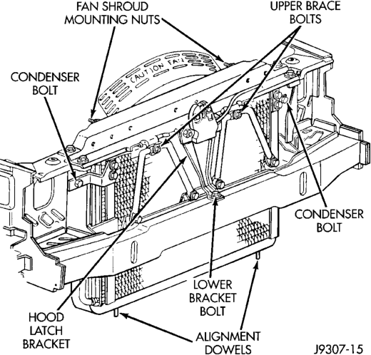
(6) Remove fan shroud and fan blade/viscous fan drive assembly from vehicle as a complete unit.
(7) After removing fan blade/viscous fan drive assembly, do not place thermal viscous fan drive in horizontal position. If stored horizontally, silicone fluid in viscous fan drive could drain into its bearing assembly and contaminate lubricant.
(8) Do not remove water pump pulley bolts at this time.
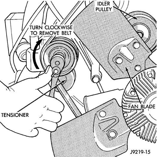
(9) Remove accessory drive belt as follows: The drive belt is equipped with a spring loaded automatic belt tensioner (Fig. 32). Relax tension from belt by rotating tensioner clockwise (as viewed from front) (Fig. 32). When all belt tension has been relaxed, remove accessory drive belt.
(10) Remove four water pump pulley-to-water pump hub bolts (Fig. 30) and remove pulley from vehicle.
(11) Remove lower radiator hose clamp and remove lower hose at water pump.
(12) Remove heater hose clamp (Fig. 33) and heater hose from heater hose coolant return tube.
(13) Loosen heater hose coolant return tube mounting bolt and nut (Fig. 33) and remove tube from water pump. Discard the old tube o-ring.
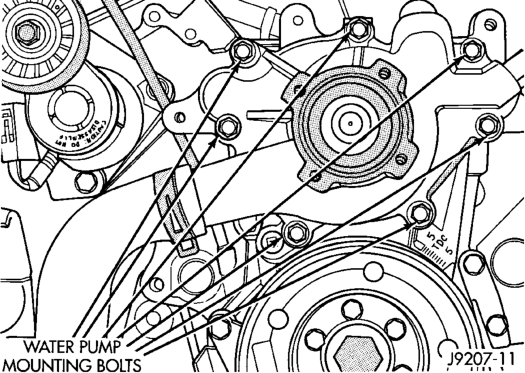
(14) Remove seven water pump mounting bolts (Fig. 34).
Typical
(15) Loosen clamp at water pump end of bypass hose (Fig. 30). Slip bypass hose from water pump while removing pump from vehicle. Discard old gasket.
CAUTION: Do not pry water pump at timing chain case/cover. The machined surfaces may be damaged resulting in leaks.
INSTALLATION
(1) Clean gasket mating surfaces. (2) Using a new gasket, install water pump to engine as follows: Guide water pump nipple into bypass hose as pump is being installed. Install water pump bolts (Fig. 34). Tighten water pump mounting bolts to 40 N·m (30 ft. lbs.) torque.
(3) Position bypass hose clamp to bypass hose. (4) Spin water pump to be sure that pump impeller does not rub against timing chain case/cover.
(5) Install a new o-ring to the heater hose coolant return tube (Fig. 33). Coat the new o-ring with antifreeze before installation.
(6) Install coolant return tube to engine (Fig. 33). Be sure the slot in tube bracket is bottomed to the mounting bolt. This will properly position return tube.
(7) Connect radiator lower hose to water pump. (8) Connect heater hose and hose clamp to coolant return tube.
(9) Install water pump pulley. Tighten bolts to 27 N·m (20 ft. lbs.) torque. Place a bar or screwdriver between water pump pulley bolts (Fig. 30) to prevent pulley from rotating.
(10) Relax tension from belt tensioner (Fig. 32). Install drive belt.
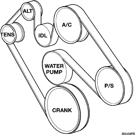
CAUTION: When installing the serpentine accessory drive belt, belt must be routed correctly. If not, engine may overheat due to water pump rotating in wrong direction. Refer to (Fig. 35) for correct belt routing. Or, refer to the Belt Routing Label located in the engine compartment. The correct belt with correct length must be used.
(11) Position fan shroud and fan blade/viscous fan drive assembly to vehicle as a complete unit.
(12) Be sure the upper and lower portions of the fan shroud are firmly connected. All air must flow through the radiator.
(13) Install two fan shroud-to-radiator nuts (Fig. 31).
(14) Be sure of at least 25 mm (1.0 inches) between tips of fan blades and fan shroud.
(15) Install fan blade/viscous fan drive assembly to water pump shaft.
(16) Fill cooling system. Refer to Refilling the Cooling System in this group.
(17) Connect negative battery cable. (18) Start and warm the engine. Check for leaks.
THERMOSTAT—4.0L ENGINE
REMOVAL
WARNING: DO NOT LOOSEN THE RADIATOR DRAINCOCK WITH THE SYSTEM HOT AND PRES- SURIZED. SERIOUS BURNS FROM THE COOLANT CAN OCCUR.
Do not waste reusable coolant. If the solution is clean, drain the coolant into a clean container for reuse.
(1) Drain the coolant from the radiator until the level is below the thermostat housing.
WARNING: CONSTANT TENSION HOSE CLAMPS ARE USED ON MOST COOLING SYSTEM HOSES. WHEN REMOVING OR INSTALLING, USE ONLY TOOLS DESIGNED FOR SERVICING THIS TYPE OF CLAMP, SUCH AS SPECIAL CLAMP TOOL (NUMBER 6094) (Fig. 51). SNAP-ON CLAMP TOOL (NUMBER HPC-20) MAY BE USED FOR LARGER CLAMPS. ALWAYS WEAR SAFETY GLASSES WHEN SERVIC- ING CONSTANT TENSION CLAMPS.
CAUTION: A number or letter is stamped into the tongue of constant tension clamps (Fig. 52). If replacement is necessary, use only an original equipment clamp with matching number or letter.
(2) Remove radiator upper hose and heater hose at thermostat housing.
(3) Disconnect wiring connector at engine coolant temperature sensor.
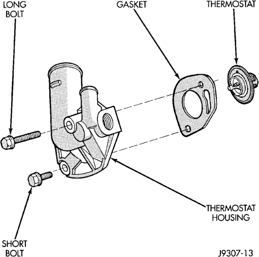
(4) Remove thermostat housing mounting bolts, thermostat housing, gasket and thermostat (Fig. 36). Discard old gasket.
(5) Clean the gasket mating surfaces.
Engine
INSTALLATION
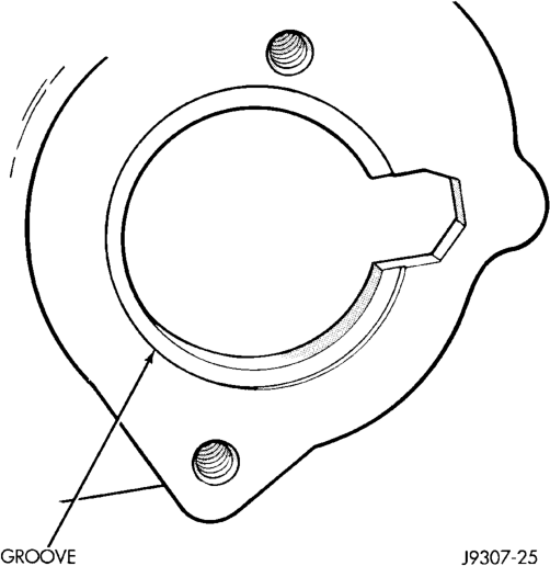
(1) Install the replacement thermostat so that the pellet, which is encircled by a coil spring, faces the engine. All thermostats are marked on the outer flange to indicate the proper installed position.
(a) Observe the recess groove in the engine cylinder head (Fig. 37). (b) Position thermostat in groove with arrow and air bleed hole on outer flange pointing up.
(2) Install replacement gasket and thermostat housing.
CAUTION: Tightening the thermostat housing unevenly or with the thermostat out of its recess, may result in a cracked housing.
(3) Tighten the housing bolts to 22 N·m (16 ft. lbs.) torque.
(4) Install hoses to thermostat housing. (5) Install electrical connector to coolant temperature sensor.
(6) Be sure that the radiator draincock is tightly closed. Fill the cooling system to the correct level with the required coolant mixture. Refer to Refilling Cooling System in this group.
(7) Start and warm the engine. Check for leaks.
THERMOSTAT—5.2L/5.9L ENGINES
REMOVAL
WARNING: DO NOT LOOSEN RADIATOR DRAIN- COCK WITH SYSTEM HOT AND PRESSURIZED. SERIOUS BURNS FROM COOLANT CAN OCCUR.
Do not waste reusable coolant. If solution is clean, drain coolant into a clean container for reuse.
If thermostat is being replaced, be sure that replacement is specified thermostat for vehicle model and engine type.
Factory installed thermostat housings on 5.2/5.9L engines are installed on a gasket with an anti-stick coating. This will aid in gasket removal and clean-up.
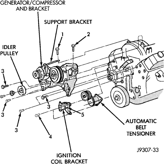
(1) Disconnect negative battery cable at battery. (2) Drain cooling system until coolant level is below thermostat. Refer to Draining Cooling System in this group. (3) Air Conditioned vehicles: Remove support bracket (generator mounting bracket-to-intake manifold) located near rear of generator (Fig. 38).
Engines
(4) On air conditioning equipped vehicles, the generator must be partially removed.
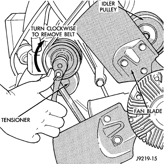
(a) Remove generator drive belt as follows: Drive belts on the 5.2L/5.9L engines are equipped with a spring loaded automatic belt tensioner (Fig. 39).
(b) Attach a socket/wrench to pulley mounting bolt of automatic belt tensioner (Fig. 39).
(c) Rotate tensioner assembly clockwise (as viewed from front) until tension has been relieved from belt.
(d) Remove belt from vehicle. (e) Remove two generator mounting bolts. Do not remove any wiring at generator. If equipped with 4WD, unplug 4WD indicator lamp wiring harness (located near rear of generator).
(f) Remove generator. Position generator to gain access for thermostat gasket removal.
(5) Remove upper radiator hose clamp (Fig. 51) and upper radiator hose at thermostat housing.
(6) Position wiring harness (behind thermostat housing) to gain access to thermostat housing.
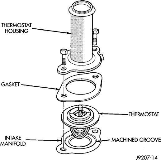
(7) Remove thermostat housing mounting bolts, thermostat housing, gasket and thermostat (Fig. 40). Discard old gasket.
INSTALLATION
(1) Clean mating areas of intake manifold and thermostat housing.
Install thermostat (spring side down) into
(2)
recessed machined groove on intake manifold (Fig. 40).
(3) Install gasket on intake manifold and over thermostat (Fig. 40).
(4) Position thermostat housing to intake manifold. Note the word FRONT stamped on housing (Fig. 41). For adequate clearance, this must be placed towards front of vehicle. The housing is slightly angled forward after installation to intake manifold.
(5) Install two housing-to-intake manifold bolts. Tighten bolts to 23 N·m (200 in. lbs.) torque.
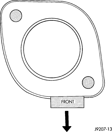
CAUTION: Housing must be tightened evenly and thermostat must be centered into recessed groove in intake manifold. If not, it may result in a cracked housing, damaged intake manifold threads or coolant leak.
(6)
Install upper radiator hose to thermostat housing.
(7) Air Conditioned vehicles:
CAUTION: When installing the serpentine accessory drive belt, belt must be routed correctly. If not, engine may overheat due to water pump rotating in wrong direction. Refer to (Fig. 42) for correct 5.2/5.9L engine belt routing. Or, refer to the Belt Routing Label located in the engine compartment. The correct belt with correct length must be used.
(a) Install generator. Tighten bolts to 41 N·m (30 ft. lbs.) torque.
(b) Install support bracket (generator mounting bracket-to-intake manifold) (Fig. 38). Tighten bolts to 54 N·m (40 ft. lbs.) torque.
(c) Position drive belt over all pulleys except idler pulley (located between generator and A/C compressor).
(d) Attach a socket/wrench to pulley mounting bolt of automatic belt tensioner (Fig. 39).
(e) Rotate socket/wrench clockwise. Place belt over idler pulley. Let tensioner rotate back into place. Remove wrench. Be sure belt is properly seated on all pulleys. (8) Fill cooling system. Refer to Refilling Cooling System in this group.
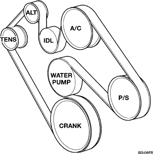
(9) Connect negative battery cable to battery. (10) Start and warm the engine. Check for leaks.
RADIATOR
REMOVAL
WARNING: DO NOT REMOVE THE CYLINDER BLOCK DRAIN PLUGS OR LOOSEN THE RADIATOR DRAINCOCK WITH THE SYSTEM HOT AND UNDER PRESSURE. SERIOUS BURNS FROM COOLANT CAN OCCUR. REFER TO COOLING SYSTEM DRAIN- ING IN THIS GROUP.
Do not waste reusable coolant. If the solution is clean, drain the coolant into a clean container for reuse.
WARNING: CONSTANT TENSION HOSE CLAMPS ARE USED ON MOST COOLING SYSTEM HOSES. WHEN REMOVING OR INSTALLING, USE ONLY TOOLS DESIGNED FOR SERVICING THIS TYPE OF CLAMP, SUCH AS SPECIAL CLAMP TOOL (NUMBER 6094) (Fig. 43). SNAP-ON CLAMP TOOL (NUMBER HPC-20) MAY BE USED FOR LARGER CLAMPS. ALWAYS WEAR SAFETY GLASSES WHEN SERVIC- ING CONSTANT TENSION CLAMPS.
CAUTION: A number or letter is stamped into the tongue of constant tension clamps (Fig. 44). If replacement is necessary, use only an original equipment clamp with matching number or letter.
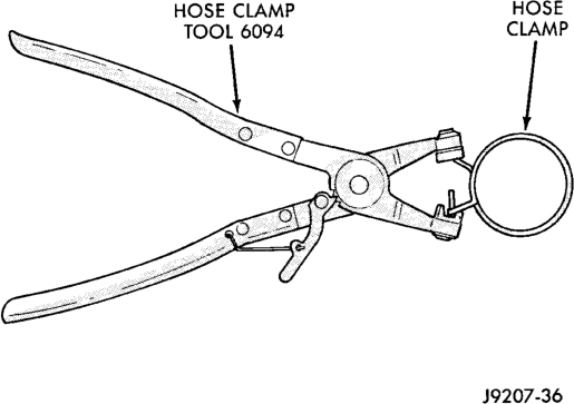
CAUTION: When removing the radiator or A/C condenser for any reason, note the location of all radiator-to-body and radiator-to-A/C condenser rubber air seals (Fig. 45). These are used at the top, bottom and sides of the radiator and A/C condenser. To prevent overheating, these seals must be installed to their original positions.
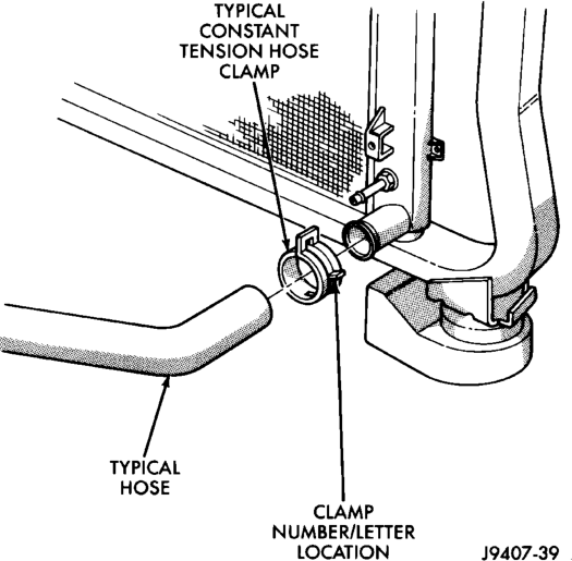
(1) Disconnect the negative battery cable at battery.
(2) Observe the previous WARNINGS and CAU- TIONS.
(3) Drain coolant from radiator. Refer to Draining Cooling System in this group.
(4) 4.0L Engine: Remove the four fan hub-to-water pump pulley mounting nuts (Fig. 46). Carefully remove the fan assembly from the water pump pulley and position to center of fan shroud. Fan belt removal is not necessary as the water pump studs will hold the pump pulley in position.
(5) Do not remove fan/viscous fan drive assembly from vehicle at this time.
(6) 5.2/5.9L Engines: The thermal viscous fan drive is attached (threaded) to the water pump hub shaft (Fig. 47). Remove fan/viscous fan drive assembly from water pump by turning mounting nut counterclockwise as viewed from front. Threads on viscous fan drive are RIGHT HAND. A Snap-On 36 MM Fan Wrench (number SP346 from Snap-On Cummins Diesel Tool Set number 2017DSP) can be used. Place a bar or screwdriver between water pump pulley bolts (Fig. 47) to prevent pulley from rotating. Drive belt removal is not necessary for removal of fan drive.
(7) Do not attempt to remove fan/viscous fan drive assembly from vehicle at this time.

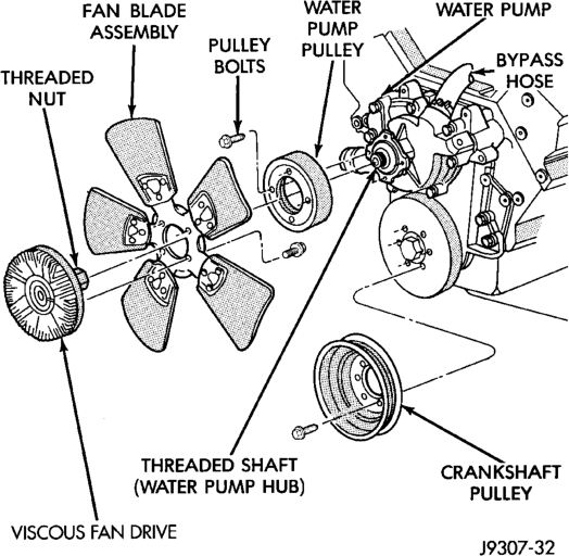

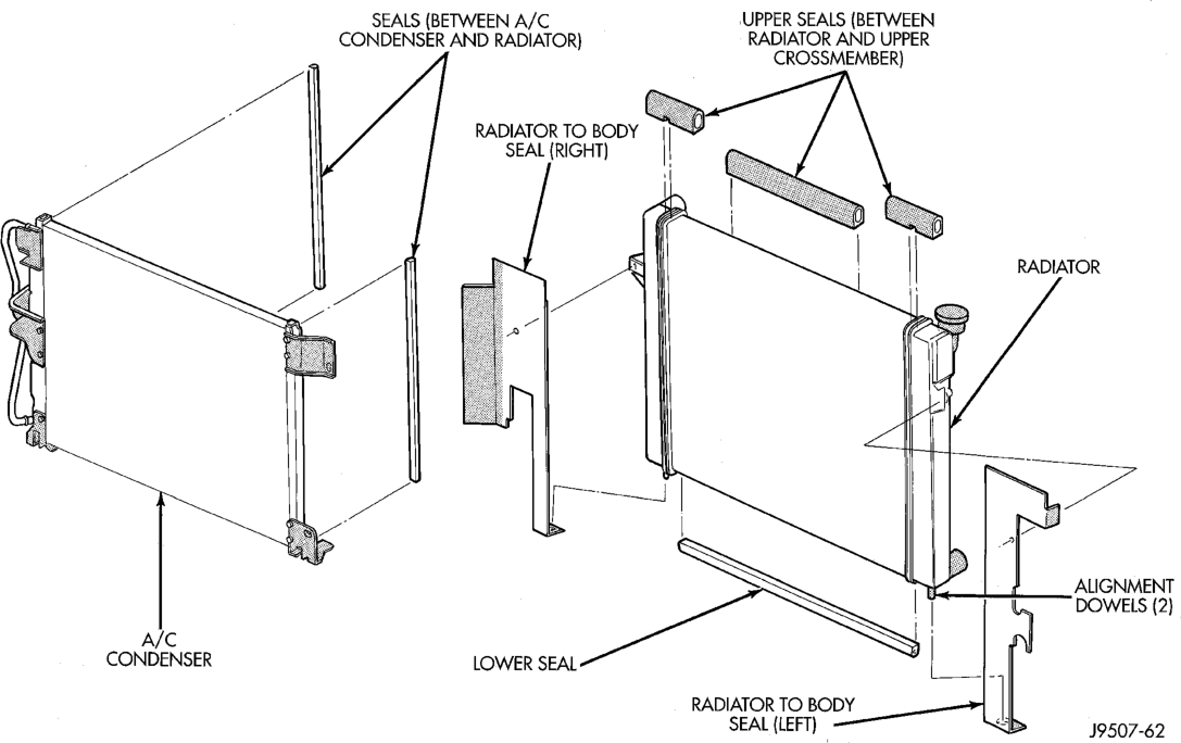

(8) Remove the two fan shroud-to-upper radiator crossmember mounting nuts (Fig. 48).
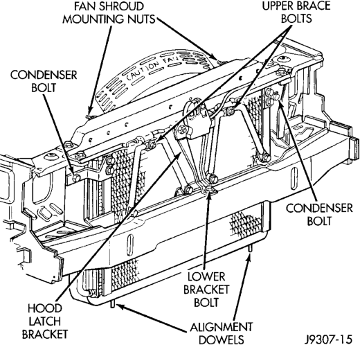
(9) Remove the fan assembly and fan shroud (as one unit) from vehicle.
(10) Special quick-connect fittings are used to join the transmission cooling lines to the radiator. Removal procedures are different between the 4.0L and 5.2/5.9L engines. Disconnect the cooling lines from the radiator. Refer to Group 21 for transmission cooling line removal and installation.
(11) The radiator upper crossmember (Fig. 49) can be adjusted left or right through the use of slotted holes. Before removal, mark the original position of the crossmember.
(12) Eight clips are used to retain a rubber seal (Fig. 49) to the body and upper radiator crossmember. Gently pry up the outboard clips (two per side) until rubber seal can be removed. Do not remove the clips entirely. Fold back the seal on both sides for access to (the hidden) grille opening reinforcement mounting bolts (Fig. 49). Remove these two bolts.
(13) Remove the grill. Refer to group 23, Body. (14) Remove the upper brace bolt from each of the two radiator braces (Fig. 48).
(15) Remove the two crossmember-to-radiator mounting nuts (Fig. 49).
(16) Working through grill opening, remove the lower bracket bolt securing lower part of hood latch support bracket to lower frame crossmember (Fig. 48).
(17) Remove the remaining four bolts securing the radiator upper crossmember to the body. Do not remove the hood latch or hood latch cable from the
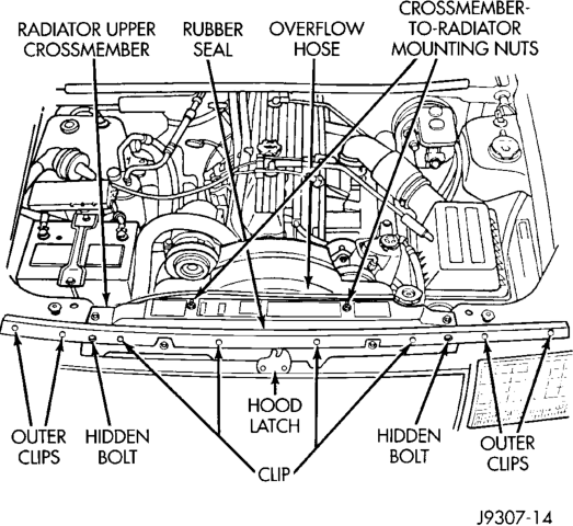
crossmember. Lift the crossmember straight up and lay to the side.
(18) Equipped with air conditioning: Remove the two A/C condenser-to-radiator mounting bolts (Fig. 48). These two bolts are also used to retain the side mounted rubber air seals (Fig. 45). These seals are compressed between the A/C condenser and the radiator. The lower part of the air seals are compressed between the radiator and the A/C condenser mounting brackets (Fig. 50). (19) Not equipped with air conditioning: Remove the two bolts retaining the side mounted rubber air seals (Fig. 45) to the radiator. The lower part of the air seals are compressed between the radiator and the radiator lower crossmember.
CAUTION: Note the location of all rubber air seals (Fig. 45). To prevent overheating, they must be installed back to their original positions.
(20) Disconnect the coolant reserve/overflow tank hose (Fig. 49) at radiator.
(21) Remove upper radiator hose at radiator. A special clamp tool (Fig. 43) must be used to remove the constant tension hose clamps.
(22) 4.0L Engine Only: Remove the lower radiator hose at the water pump end.
(23) To gain access to lower radiator hose clamp at radiator, gently lift the radiator a slight amount. Remove hose clamp and hose.
(24) The lower part of radiator is equipped with two alignment dowel pins (Fig. 48) (Fig. 50). They are located on the bottom of radiator tank and fit into rubber grommets. These rubber grommets are pressed into the radiator lower crossmember.
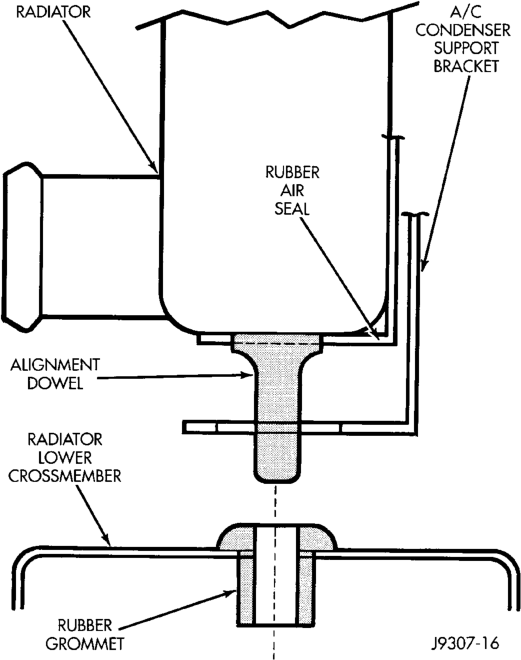
WARNING: THE AIR CONDITIONING SYSTEM (IF EQUIPPED) IS UNDER A CONSTANT PRESSURE EVEN WITH THE ENGINE OFF. REFER TO REFRIG- ERANT WARNINGS IN GROUP 24, HEATING AND AIR CONDITIONING BEFORE HANDLING ANY AIR CONDITIONING COMPONENT.
(25) If equipped with an auxiliary automatic transmission oil cooler, use caution when removing radiator. The oil cooler lines are routed through a rubber air seal on the left side of radiator. Do not cut or tear this seal.
(26) Gently lift up and remove radiator from vehicle. Be careful not to scrape the radiator fins against any other component. Also be careful not to disturb the air conditioning condenser (if equipped).
INSTALLATION
CAUTION: Before installing the radiator or A/C condenser, be sure the radiator-to-body and radiator-to-A/C condenser rubber air seals (Fig. 45) are properly fastened to their original positions. These are used at the top, bottom and sides of the radiator and A/C condenser. To prevent overheating, these seals must be installed to their original positions.
(1) Equipped with air conditioning: Gently lower the radiator into the vehicle. Guide the two radiator alignment dowels through the holes in the rubber air seals first and then through the A/C support brackets (Fig. 50). Continue to guide the alignment dowels into the rubber grommets located in lower radiator crossmember (Fig. 50). The holes in the L-shaped brackets (located on bottom of A/C condenser) must be positioned between bottom of rubber air seals and top of rubber grommets.
(2) Not equipped with air conditioning: Gently lower the radiator into the vehicle. Guide the two radiator alignment dowels through the holes in the rubber air seals. Continue to guide the alignment dowels into the rubber grommets located in lower radiator crossmember.
(3) Connect the lower radiator hose and hose clamp to radiator.
CAUTION: The tangs on the hose clamp must be positioned straight down.
(4) 4.0L Engine: Connect the lower radiator hose at the water pump.
(5) Connect the upper radiator hose at the radiator.
(6) Equipped with air conditioning: Install the two A/C condenser- to-radiator mounting bolts (Fig. 48). These two bolts are also used to retain the rubber air seal (Fig. 45) to the sides of radiator.
(7) Not equipped with A/C: Install the two bolts retaining the rubber air seal (Fig. 45) to sides of radiator.
(8) Install coolant reserve/overflow tank hose at radiator.
(9) If radiator-to-upper crossmember rubber isolators were removed from radiator, install them. Tighten mounting nuts to 3 N·m (24-36 in. lbs.) torque. Position upper radiator crossmember to radiator.
(10) Working through grill opening, install and tighten the hood latch support bracket-to-lower frame crossmember bolt (Fig. 48).
(11) Install the four bolts securing the radiator upper crossmember to the body (Fig. 49).
(12) Install two nuts securing the radiator to the upper radiator crossmember (Fig. 49). Tighten nuts to 2 N·m (18-21 in. lbs.) torque.
(13) Install the upper bolt to each radiator brace (Fig. 48).
(14) Install the grill. Refer to group 23, Body. (15) Install the rubber seal (Fig. 49) to the four (outer) seal mounting clips on vehicle body. Press down on clips until seated.
(16) Install the transmission cooler lines to radiator. Refer to Group 21 for installation.
(17) Position the fan assembly and fan shroud (as one unit) to the vehicle.
(18) Position fan shroud to radiator. Be sure the alignment tabs at the lower part of shroud are placed into the slots near lower part of radiator. Be sure the upper and lower portions of the fan shroud are firmly connected. All air must flow through the radiator.
(19) Install the two nuts securing the fan shroud to the upper radiator crossmember (Fig. 48).
(20) 4.0L Engine: Install the four nuts securing the fan assembly to the water pump (Fig. 46). Tighten nuts to 27 N·m (20 ft. lbs.) torque.
(21) 5.2/5.9L Engines: Install the fan/viscous fan drive assembly to the water pump.
(22) Rotate the fan blades (by hand) and check for interference at fan shroud. (23) Be sure of at least 25 mm (1.0 inches) between tips of fan blades and fan shroud.
(24) Fill cooling system. Refer to Refilling Cooling System in this group.
(25) Connect battery cable at battery. (26) Start and warm engine. Check for leaks.
WATER PUMP BYPASS HOSE—5.2L/5.9L
REMOVAL
WARNING: CONSTANT TENSION HOSE CLAMPS ARE USED ON MOST COOLING SYSTEM HOSES. WHEN REMOVING OR INSTALLING, USE ONLY TOOLS DESIGNED FOR SERVICING THIS TYPE OF CLAMP, SUCH AS SPECIAL CLAMP TOOL (NUMBER 6094) (Fig. 51). SNAP-ON CLAMP TOOL (NUMBER HPC-20) MAY BE USED FOR LARGER CLAMPS. ALWAYS WEAR SAFETY GLASSES WHEN SERVIC- ING CONSTANT TENSION CLAMPS.
CAUTION: A number or letter is stamped into the tongue of constant tension clamps (Fig. 52). If replacement is necessary, use only an original equipment clamp with matching number or letter.
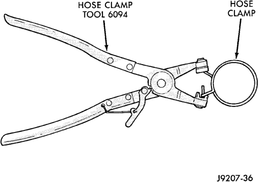
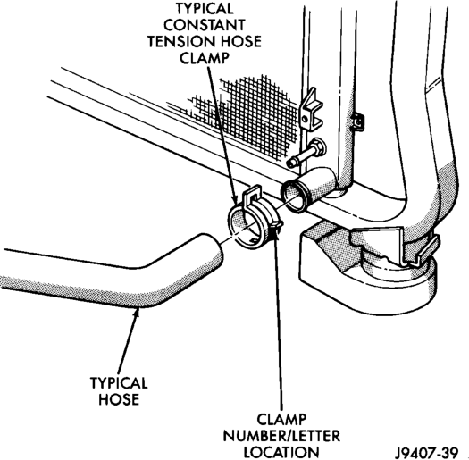
If equipped with A/C, the generator and A/C compressor along with their common mounting bracket (Fig. 53) must be partially removed. Removing generator or A/C compressor from their mounting bracket is not necessary. Also, discharging A/C system is not necessary. Do not remove any refrigerant lines from A/C compressor.
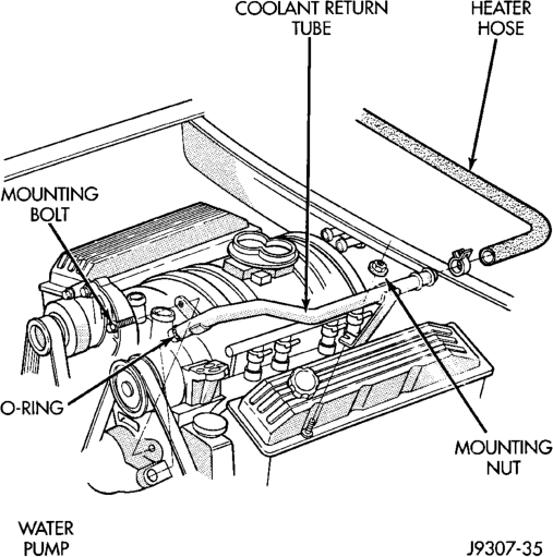
Bracket—5.2/5.9L Engines
WARNING: THE A/C SYSTEM IS UNDER PRES- SURE EVEN WITH ENGINE OFF. REFER TO REFRIGERANT WARNINGS IN GROUP 24, HEATING AND AIR CONDITIONING.
(1) Disconnect negative battery cable from battery. (2) Partially drain cooling system. Refer to Draining Cooling System in this group. Do not waste reusable coolant. If solution is clean, drain coolant into a clean container for reuse.
(3) Remove upper radiator hose clamp (Fig. 51) and hose at radiator.
(4) Unplug wiring harness from A/C compressor. (5) Remove air duct at throttle body. (6) Disconnect A/C lines from clip at intake manifold.
(7) Remove heater hose coolant return tube mounting bolt and nut (Fig. 54). Remove tube from engine and discard the old tube o-ring.
(8) Remove accessory drive belt as follows: The drive belt is equipped with a spring loaded automatic belt tensioner (Fig. 55). Relax tension from belt by rotating tensioner clockwise (as viewed from front) (Fig. 55). When all belt tension has been relaxed, remove accessory drive belt.
(9) The drive belt idler pulley must be removed to gain access to one of A/C compressor/generator bracket mounting bolts. Remove idler pulley bolt and remove idler pulley (Fig. 53).
(10) Remove oil dipstick tube mounting bolt at side of A/C- generator mounting bracket.
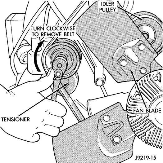
(11) Disconnect speed control cable and throttle cable at throttle body. Refer to Accelerator Pedal and Throttle Cable in Group 14, Fuel System for throttle cable removal and installation. Refer to Group 8H for removal and installation of speed control cable.
(12) Remove bracket-to-intake manifold bolts (number 1 and 2) (Fig. 53).
(13) Remove bracket bolts (Fig. 53). (14) Lift and position generator and A/C compressor (along with their common mounting bracket) to gain access to bypass hose. A block of wood may be used to hold assembly in position.
(15) Loosen and position both hose clamps to center of bypass hose. Remove hose from vehicle.
INSTALLATION
(1) Position bypass hose clamps to center of hose. (2) Install bypass hose to engine. (3) Secure both hose clamps (Fig. 51). (4) Install generator-A/C mounting bracket assembly to engine. Tighten bolts (number 1 and 2) (Fig. 53) to 54 N·m (40 ft. lbs.) torque. Tighten bolts (number 3) (Fig. 53) to 40 N·m (30 ft. lbs.) torque.
(5) Install a new o-ring to the heater hose coolant return tube (Fig. 54). Coat the new o-ring with antifreeze before installation.
(6) Install coolant return tube to engine (Fig. 54). Be sure the slot in tube bracket is bottomed to the mounting bolt. This will properly position return tube.
(7) Connect throttle body control cables. (8) Install oil dipstick mounting bolt. (9) Install idler pulley. Tighten pulley bolt to 54 N·m (40 ft. lbs.) torque.
(10) Relax tension from belt tensioner (Fig. 55). Install drive belt.
CAUTION: When installing serpentine accessory drive belt, belt must be routed correctly. If not, engine may overheat due to water pump rotating in wrong direction. Refer to (Fig. 56) for correct belt routing. Or, refer to the Belt Routing Label located in the engine compartment. The correct belt with correct length must be used.
(11) Install air duct to throttle body. (12) Install upper radiator hose to radiator. (13) Connect wiring harness to A/C compressor. (14) Connect A/C lines to clip at intake manifold. (15) Fill cooling system. Refer to Refilling the Cooling System in this group.
(16) Start and warm the engine. Check for leaks.
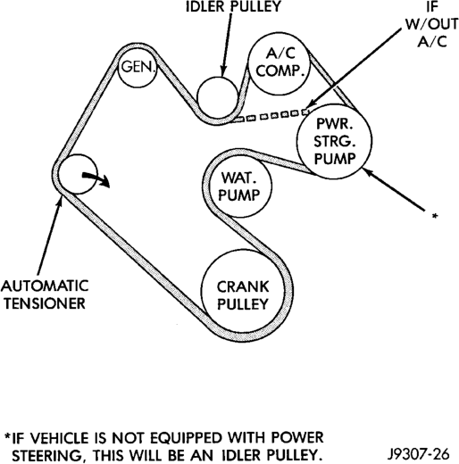
BLOCK HEATER
REMOVAL
(1) Disconnect battery negative cable. (2) Drain coolant from radiator. Refer to Draining Cooling System in this group.
(3) Raise vehicle. (4) Remove engine cylinder block drain plug(s) located on the sides of cylinder block above the oil pan rail (Fig. 57) (Fig. 58).
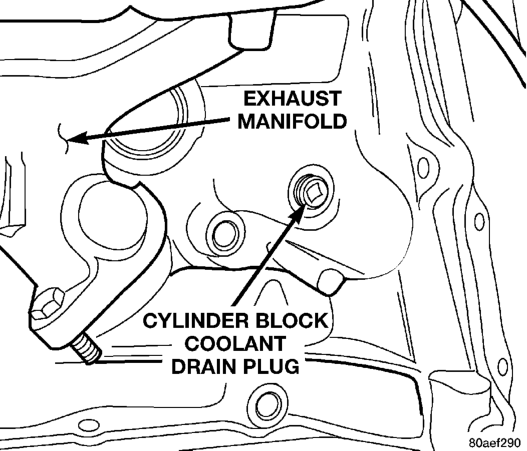
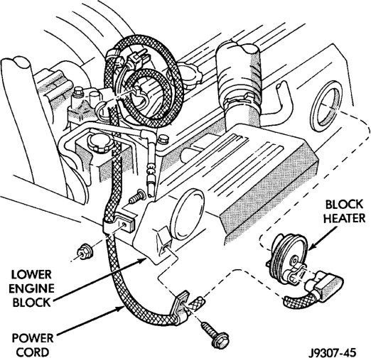
Engines—Typical
(5) Remove power cord from block heater (Fig. 59) (Fig. 60).
(6) Loosen screw at center of block heater. Remove heater assembly.
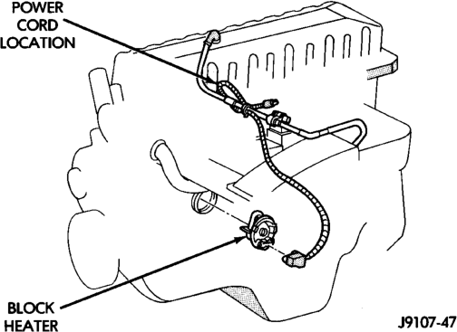
INSTALLATION
(1) Thoroughly clean cylinder block core hole and block heater seat.
(2) Insert block heater assembly with element loop pointing down.
(3) With block heater fully seated, tighten center screw to 4 N·m (32 in. lbs.) torque on 4.0L engines and 2 N·m (17 in. lbs.) torque on 5.2L/5.9L engines.
(4) Fill cooling system with recommended coolant. Refer to Refilling Cooling System section in this group.
(5) Start and warm the engine. Check for leaks.
ACCESSORY DRIVE BELT
Correct drive belt tension is required to ensure optimum performance of the belt driven engine accessories. There are different types of adjustment gauges for checking either a serpentine or a V-type belt. Refer to the instructions supplied with the gauge. Use the correct gauge when checking belt tension. Place gauge in the middle of the section of belt being tested (between two pulleys) to check tension. Do not allow the gauge (or gauge adapter) to contact anything but the belt.
BELT SCHEMATICS
The belt routing schematics are published from the latest information available at the time of publication. Vehicles not equipped with Power Steering have an idler pulley in place of the power steering pump pulley. If anything differs between these schematics and the Belt Routing Label, use the schematics on Belt Routing Label. This label is located in the engine compartment.
Refer to (Fig. 61) (Fig. 62) for correct belt routing, or refer to Belt Routing Label located in the vehicle engine compartment.
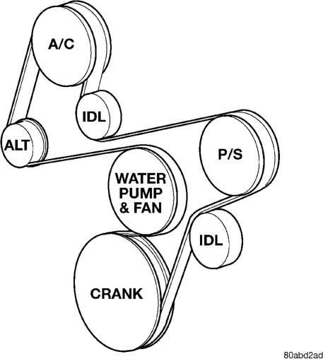
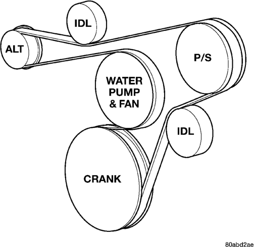
BELT REPLACEMENT—4.0L ENGINES
REMOVAL
Belt tension is adjusted at the power steering pump bracket and idler pulley assembly.
(1) Disconnect negative battery cable from battery. (2) Loosen idler pulley bolt (Fig. 63). (3) Loosen tension adjusting bolt (Fig. 63) and remove accessory drive belt.
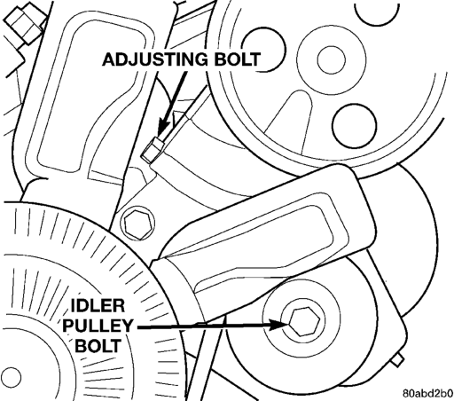
Pulley
INSTALLATION
(1) Check condition of all pulleys.
CAUTION: When installing the serpentine accessory drive belt, the belt MUST be routed correctly. If not, the engine may overheat due to the water pump rotating in the wrong direction. Refer to (Fig. 61) for correct belt routing.
(2) Install new belt. Install belt tension gauge C-4162 and tighten adjustment bolt (Fig. 63) until belt tension is within specification range. Refer to the end of this group for Drive Belt Tension specifications.
(3) Tighten idler pulley bolt and re-check belt tension. Adjust if necessary.
BELT REPLACEMENT—5.2L/5.9L ENGINES
Drive belts on the 5.2L/5.9L engines are equipped with a spring loaded automatic belt tensioner (Fig. 64).
CAUTION: Do not attempt to check belt tension with a belt tension gauge on vehicles equipped with an automatic belt tensioner. Refer to Automatic Belt Tensioner in this group.
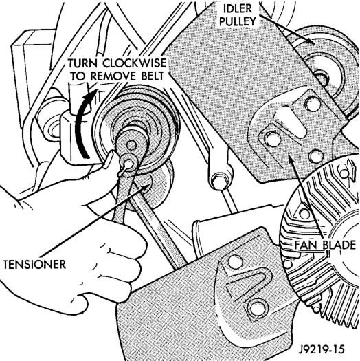
REMOVAL
(1) Attach a socket/wrench to pulley mounting bolt of automatic belt tensioner (Fig. 64).
(2) Rotate tensioner assembly clockwise (as viewed from front) until tension has been relieved from belt.
(3) Remove belt from idler pulley first. (4) Remove belt from vehicle.
INSTALLATION
CAUTION: When installing serpentine accessory drive belt, the belt must be routed correctly. If not, engine may overheat due to water pump rotating in wrong direction. Refer to (Fig. 62) for correct engine belt routing. The correct belt with correct length must be used.
(1) Position drive belt over all pulleys except idler pulley. This pulley is located between generator and A/C compressor.
(2) Attach a socket/wrench to pulley mounting bolt of automatic tensioner (Fig. 64).
(3) Rotate socket/wrench clockwise. Place belt over idler pulley. Let tensioner rotate back into place. Remove wrench. Be sure belt is properly seated on all pulleys.
(4) Check belt indexing marks. Refer to Automatic Belt Tensioner.
AUTOMATIC BELT TENSIONER
NOTE: On 5.2/5.9L engines, the tensioner is equipped with an indexing arrow (Fig. 65) on back of tensioner and an indexing mark on tensioner housing. If a new belt is being installed, arrow must be within approximately 3 mm (1/8 in.) of indexing mark (point B-) (Fig. 65). Belt is considered new if it has been used 15 minutes or less.
If the above specification cannot be met, check for: • The wrong belt being installed (incorrect length/ width)
• Worn bearings on an engine accessory (A/C compressor, power steering pump, water pump, idler pulley or generator)
• A pulley on an engine accessory being loose • Misalignment of an engine accessory • Belt incorrectly routed.
NOTE: A used belt should be replaced if tensioner indexing arrow has moved to point-A (Fig. 65). Tensioner travel stops at point-A.
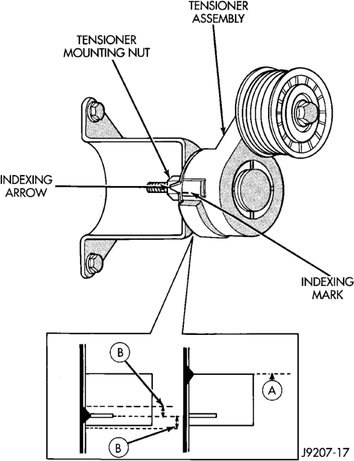
Engines
REMOVAL
(1) Remove accessory drive belt. Refer to Belt Replacement/Adjustment in this group.
(2) Disconnect wiring and secondary cable from ignition coil. (3) Remove ignition coil from coil mounting bracket (two bolts). Do not remove coil mounting bracket from cylinder head.
(4) Remove tensioner assembly from mounting bracket (one nut) (Fig. 65).
WARNING: BECAUSE OF HIGH SPRING PRES- SURE, DO NOT ATTEMPT TO DISASSEMBLE AUTO- MATIC TENSIONER. UNIT IS SERVICED AS AN ASSEMBLY (EXCEPT FOR PULLEY).
(5) Remove pulley bolt. Remove pulley from tensioner.
INSTALLATION
(1) Install pulley and pulley bolt to tensioner. Tighten bolt to 61 N·m (45 ft. lbs.) torque.
(2) Install tensioner assembly to mounting bracket. An indexing tab is located on back of tensioner. Align this tab to slot in mounting bracket. Tighten nut to 67 N·m (50 ft. lbs.) torque.
(3) Connect all wiring to ignition coil. (4) Install coil to coil bracket. If nuts and bolts are used to secure coil to coil bracket, tighten to 11 N·m (100 in. lbs.) torque. If coil mounting bracket has been tapped for coil mounting bolts, tighten bolts to 5 N·m (50 in. lbs.) torque.
CAUTION: To prevent damage to coil case, coil mounting bolts must be torqued.
(5) Install drive belt. Refer to Belt Removal/Installation in this group.
(6) Check belt indexing marks (Fig. 65).
COOLING SYSTEM FAN—4.0L ENGINE
REMOVAL
(1) Remove the four fan hub-to-water pump pulley mounting nuts (Fig. 66). Carefully remove the fan assembly from the water pump pulley and position to center of fan shroud. Fan belt removal is not necessary as the water pump studs will hold the pump pulley in position. Do not remove fan assembly from vehicle at this time.
(2) Remove the two fan shroud-to-upper radiator crossmember mounting nuts (Fig. 67).
(3) Remove fan, viscous fan drive and fan shroud as an assembly from the vehicle.
(4) Remove the four fan blade-to-viscous fan drive mounting bolts. Remove viscous fan drive from fan blades.
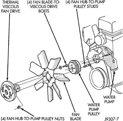
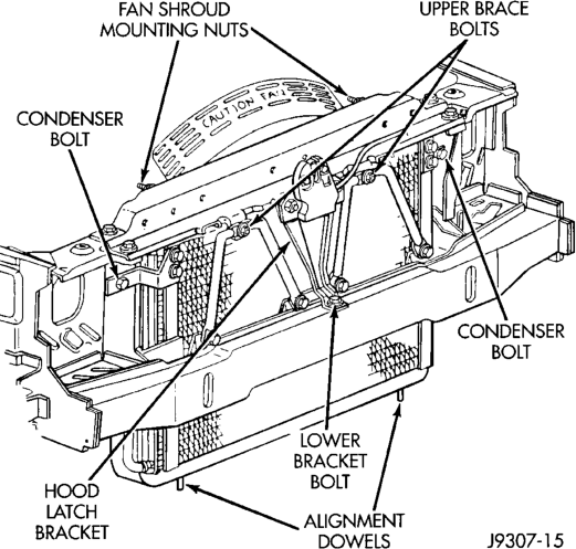
(5) After removing fan blade/fan drive assembly do not place the thermal viscous fan drive in the horizontal position. If stored horizontally, the silicone fluid in the viscous fan drive could drain into the bearing assembly and contaminate the lubricant.
INSTALLATION
(1) Assemble fan blades to viscous fan drive. Tighten mounting bolts to 24 N·m (18 ft. lbs.) torque.
(2) Position fan, viscous fan drive and fan shroud to the engine as one assembly.
(3) Position fan shroud to radiator. Be sure the alignment tabs at the lower part of shroud are placed into the slots near lower part of radiator. Be sure the upper and lower portions of the fan shroud are firmly connected. All air must flow through the radiator.
(4) Position mounting flange of fan/viscous fan drive assembly onto water pump pulley. Install four nuts and tighten to 24 N·m (18 ft. lbs.) torque.
(5) Install two fan shroud mounting nuts. Be sure of at least 25 mm (1.0 inches) between tips of fan blades and fan shroud.
COOLING SYSTEM FAN—5.2L ENGINE
REMOVAL
(1) Disconnect negative battery cable from battery. (2) The thermal viscous fan drive/fan blade assembly is attached (threaded) to water pump hub shaft (Fig. 68). Remove fan blade/viscous fan drive assembly from water pump by turning mounting nut counterclockwise as viewed from front. Threads on viscous fan drive are RIGHT HAND. A Snap-On 36 MM Fan Wrench (number SP346 from Snap-On Cummins Diesel Tool Set number 2017DSP) can be used. Place a bar or screwdriver between water pump pulley bolts to prevent pulley from rotating.
(3) Do not attempt to remove fan/viscous fan drive assembly from vehicle at this time.
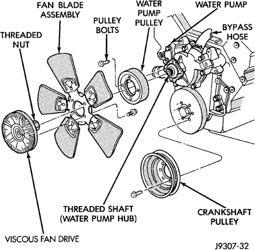
Engines
(4) Do not unbolt fan blade assembly from viscous fan drive at this time.
(5) Remove two fan shroud-to-upper crossmember nuts (Fig. 67).
(6) Remove fan shroud and fan blade/viscous fan drive assembly as a complete unit from vehicle.
(7) After removing fan blade/viscous fan drive assembly, do not place viscous fan drive in horizontal position. If stored horizontally, silicone fluid in the viscous fan drive could drain into its bearing assembly and contaminate lubricant.
CAUTION: Do not remove water pump pulley-towater pump bolts. This pulley is under spring tension.
(8) Remove four bolts securing fan blade assembly to viscous fan drive.
INSTALLATION
(1) Install fan blade assembly to viscous fan drive. Tighten bolts to 23 N·m (17 ft. lbs.) torque.
(2) Position fan shroud and fan blade/viscous fan drive assembly to vehicle as a complete unit.
(3) Position fan shroud to radiator. Be sure the alignment tabs at the lower part of shroud are placed into the slots near lower part of radiator. Install and tighten the two fan shroud-to-upper crossmember mounting nuts.
Be sure of at least 25 mm (1.0 inches) between tips of fan blades and fan shroud.
(4) Install fan blade/viscous fan drive assembly to water pump shaft.
(5) Connect negative battery cable.
ELECTRIC COOLING FAN—5.9L ENGINE
WARNING: THE FAN CAN COME ON AT ANY TIME WHEN THE IGNITION KEY IS IN THE “RUN” POSI- TION. MAKE SURE TO TURN THE KEY TO “OFF” WHEN SERVICING THIS COMPONENT.
REMOVAL
(1) Disconnect battery negative cable. (2) Partially drain cooling system to allow upper radiator hose removal from radiator.
(3) Disconnect upper hose coolant switch connector (Fig. 69).
(4) Remove clamp from upper hose/radiator connection and remove hose from radiator inlet only. Secure hose out of way.
(5) Disconnect the cooling fan electrical connector (Fig. 70).
(6) Remove cooling fan module mounting bolts (Fig. 70).
(7) Lift fan module up off of mounts and out of engine compartment.
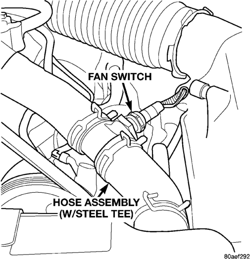
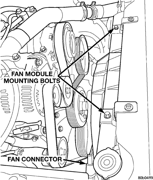
INSTALLATION
If replacing fan module assembly, transfer any brackets, etc. not included with new module assembly.
(1) Lower fan module into engine compartment and into its respective radiator mounts.
(2) Install fan module mounting bolts (Fig. 70) and torque to 16 N·m (140 in. lbs.)
(3) Connect fan module connector (Fig. 70). (4) Install upper hose to radiator inlet and install clamp.
(5) Connect upper hose coolant switch connector (Fig. 69).
(6) Fill cooling system. (Refer to Filling Cooling System in this Group for the correct procedure.)
(7) Connect battery negative cable. (8) Start engine and check for leaks. Check cooling fan for proper operation.
VISCOUS FAN DRIVE

Refer to Cooling System Fan removal and installation procedures of the viscous fan drive unit procedures.
Viscous Fan Drive Fluid Pump Out Requirement:
After installing a NEW viscous fan drive, bring the engine speed up to approximately 2000 rpm and hold for approximately two minutes. This will ensure proper fluid distribution within the drive.
CLEANING AND INSPECTION
RADIATOR CAP—INSPECTION
Visually inspect the pressure valve gasket on the cap. Replace cap if the gasket is swollen, torn or worn. Inspect the area around radiator filler neck for white deposits that indicate a leaking cap.
COOLING SYSTEM
CAUTION: The cooling system normally operates at 97 to 124 kPa (14 to 18 psi) pressure. Exceeding this pressure may damage the radiator or hoses.
CLEANING Drain cooling system and refill with water. Run engine with radiator cap installed until upper radiator hose is hot. Stop engine and drain water from system. If water is dirty, fill system with water, run engine and drain system. Repeat until water drains clean.
RADIATOR—CLEANING
The radiator and air conditioning fins should be cleaned when an accumulation of bugs, leaves etc. has occurred. Clean radiator fins are necessary for good heat transfer. With the engine cold, apply cold water and compressed air to the back (engine side) of the radiator to flush the radiator and/or A/C condenser of debris.
VISCOUS FAN—INSPECTION
The fan blades cannot be repaired. If the fan is damaged, it must be replaced. Inspect the fan blades as follows:
Lay fan blade assembly on a flat surface with leading edge facing down. With tip of blade touching flat surface, replace fan if clearance between opposite blade and surface is greater than 2.0 mm (.090 inch). Rocking motion of opposite blades should not exceed 2.0 mm (.090 inch). Test all blades in this manner.
WARNING: IF FAN IS NOT WITHIN SPECIFICA- TIONS, DO NOT ATTEMPT TO BEND OR STRAIGHTEN FAN.
Inspect fan assembly for cracks, bends, loose rivets or broken welds. Replace fan if any damage is found.
CAUTION: If the fan blade assembly is replaced because of mechanical damage, the water pump and viscous fan drive should also be inspected. These components could have been damaged due to excessive vibration.
WATER PUMP—INSPECTION
Replace water pump assembly if it has any of the following conditions:
• The body is cracked or damaged • Water leaks from shaft seal. This is evident by traces of coolant below vent hole
• Loose or rough turning bearing. Also inspect viscous fan drive
• Impeller rubs either the pump body or timing chain case/cover
COOLING SYSTEM HOSES—INSPECTION
Inspect the hoses at regular intervals. Replace hoses that are cracked, feel brittle when squeezed, or swell excessively when the system is pressurized.
For all vehicles: In areas where specific routing clamps are not provided, be sure that hoses are positioned with sufficient clearance. Check clearance from exhaust manifolds and pipe, fan blades, drive belts and sway bars. Improperly positioned hoses can be damaged, resulting in coolant loss and engine overheating.
Ordinary worm gear type hose clamps (when equipped) can be removed with a straight screwdriver or a hex socket. To prevent damage to hoses or clamps, the hose clamps should be tightened to 4 N·m (34 in. lbs.) torque. Do not over tighten hose clamps.
When performing a hose inspection, inspect the radiator lower hose for proper position and condition of the internal spring.
SPECIFICATIONS
COOLING SYSTEM CAPACITIES
ENGINE CAPACITY*
4.0L 11.4L (12.0 QUARTS)
5.2L/5.9L 14.1L (14.9 QUARTS)
* Includes coolant recovery bottle capacity
ACCESSORY DRIVE BELT TENSION
4.0L Engine
BELT TENSION
NEW ACCESSORY DRIVE BELT*
800-900 N (180-200 lbs.)
USED ACCESSORY DRIVE BELT
623-712 N (140-160 lbs.)
*Belt is considered new if it has been used for 15 minutes or less
Specifications for use with a belt tension gauge. Refer to operating instructions supplied with gauge.
5.2L/5.9L Engine
Do not attempt to check belt tension with a tension gauge. System is equipped with an automatic tensioner. Refer to Automatic Belt Tensioner if Group 7, Cooling System
TORQUE SPECIFICATIONS
DESCRIPTION TORQUE Automatic Belt Tensioner to
Mounting Bracket (5.2/5.9L) Bolts . . . . . . . . . . . . . . . . . . . . . . .67 N·m (50 ft. lbs.) Automatic Belt Tensioner to
Block (5.2/5.9L) Bolts . . . . . . . . . . . . . . . . . . . . . . .41 N·m (30 ft. lbs.) Automatic Belt Tensioner
Pulley (5.2/5.9L) Bolt. . . . . . . . . . . . . . . . . . . . . . . .61 N·m (45 ft. lbs.) Belt Tensioner Bracket to
Block (4.0L) Bolts . . . . . . . . . . . . . . . . . . . . . . .47 N·m (35 ft. lbs.) Belt Idler Pulley (4.0L) Fixed Pulley Bolt . . . . . . . . . . . . .57 N·m (42 ft. lbs.) Belt Tensioner Pulley (4.0L) Bolt. . . . . . . . . . . . . . . . . . . . . . . .57 N·m (42 ft. lbs.) Block Heater (4.0L) Bolt . . . . . . . . . . . . . . . . . . . . . . . .4 N·m (32 in. lbs.) Block Heater (5.2/5.9L) Bolt . . . . . . . . . . . . . . . . . . . . . . . .2 N·m (17 in. lbs.) Fan Blade Assy. to Viscous
Drive (4.0L) Bolts. . . . . . . . . . . . . . . . . . . . . .23 N·m (200 in. lbs.) Fan/Drive Assy. to Water
Pump (4.0L) Nuts . . . . . . . . . . . . . . . . . . . . . .23 N·m (200 in. lbs.) Fan Module to Radiator
Support (5.9L) Bolts. . . . . . . . . . . . . . . . . . . . . .16 N·m (140 in. lbs.) Generator Mounting (4.0L) Bolts . . . . . . . . . . . . . . . . . . . . . . .57 N·m (42 ft. lbs.) Radiator Upper Isolator to
Crossmember Nuts. . . . . . . . . . . . . . . . . . . . . . . .3 N·m (20 in. lbs.) Radiator Upper Isolator to Radiator Nuts. . . . . . . . . . . . . . . . . . . . . . . .4 N·m (36 in. lbs.) Radiator Brace Bolts. . . . . . . . . . . . . . . . . . . . . . .10 N·m (90 in. lbs.) Thermostat Housing Bolts . . . . . . . . . . . . . . . . . . . . . . .22 N·m (16 ft. lbs.) Upper Radiator Crossmember to Body Bolts. . . . . . . . . . . . . . . . . . . . . . .10 N·m (90 in. lbs.) Water Pump (4.0L) Bolts . . . . . . . . . . . . . . . . . . . . . . .30 N·m (22 ft. lbs.) Water Pump (5.2/5.9L) Bolts . . . . . . . . . . . . . . . . . . . . . . .40 N·m (30 ft. lbs.) Water Pump Pulley (5.2/5.9L) Bolts . . . . . . . . . . . . . . . . . . . . . . .27 N·m (20 ft. lbs.)
SPECIAL TOOLS
COOLING
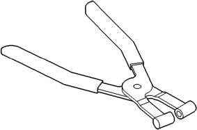
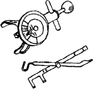
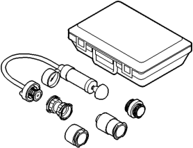
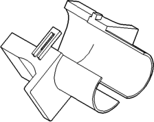
COOLANT ROUTING
For cooling system flow routing, refer to (Fig. 1)
RADIATOR
The radiator used with the 2.5L diesel is constructed of a horizontal cross-flow brass core with plastic side tanks.
CAUTION: Plastic tanks, while stronger than brass, are subject to damage by impact, such as wrenches.
If the plastic tank has been damaged, the tank and/or gaskets are available for service repair. Tank replacement should be done by qualified personal with proper equipment.
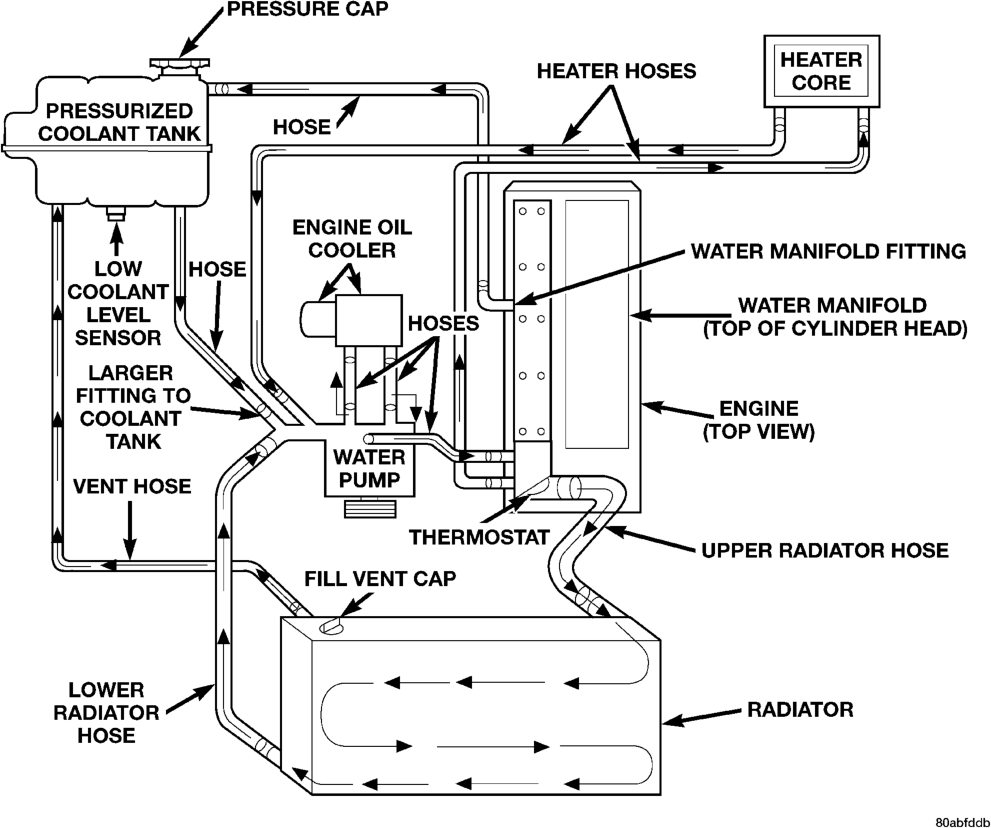
ENGINE ACCESSORY DRIVE BELTS
The accessory drive components are operated by a single, crankshaft driven, serpentine drive belt. Initial belt adjustment is done with an adjustable tensioner pulley. After the initial adjustment is performed, an automatic belt tensioner is used to maintain correct belt tension at all times.
CAUTION: When installing a serpentine accessory drive belt, the belt MUST be routed correctly. If not, the engine may overheat due to water pump rotating in wrong direction. Refer to the engine Belt Schematic in Specification section at the end of this group for the correct belt routing.
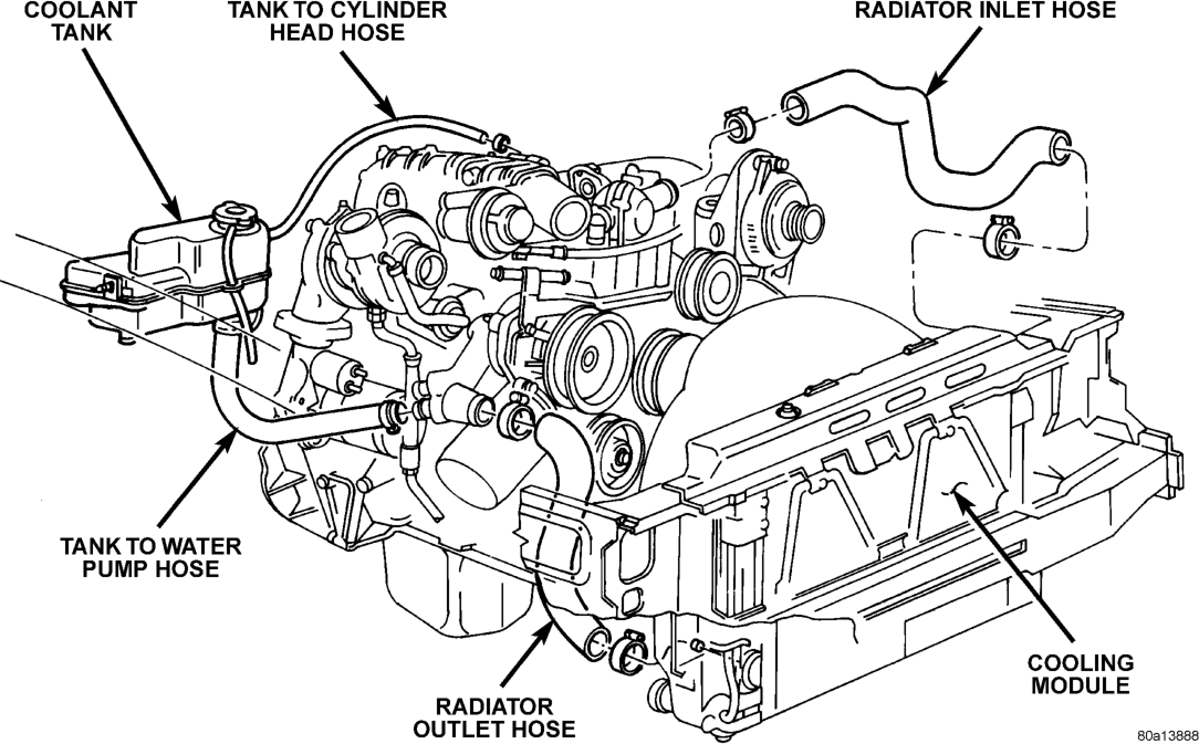
COOLANT TANK
A pressurized, plastic coolant tank is used with the cooling system. This separate tank should be considered part of the radiator. The tank is located at the right-rear side of the engine compartment and is mounted as the highest point of the cooling system. This will allow any air or vapor exceeding the pressure/vent cap rating to escape through the cap. Coolant will flow through the tank at all times during engine operation whether the engine is cold or at normal operating temperature. The coolant tank is equipped with a cam type pressure/vent cap. Refer to Pressure/Vent Cap for additional information.
A separate coolant reserve/overflow tank is not used with this system.
The low coolant level sensor is located on the bottom of the tank (Fig. 2).
WATER PUMP
A centrifugal water pump circulates coolant through the water jackets, passages, water manifold, radiator core, pressurized coolant tank, cooling system hoses and heater core. The pump is driven from the engine crankshaft by a drive belt. The water pump is bolted to the water pump adapter (Fig. 3). The water pump adapter is bolted to the engine.
The water pump impeller is pressed onto the rear of a shaft that rotates in bearings pressed into the housing. The bottom of the housing is equipped with a small vent tube (Fig. 3) to allow seepage to escape. A drain hose is attached to this tube. The water pump seals are lubricated by the antifreeze in the coolant mixture. No additional lubrication is necessary.
6A rubber o-ring (instead of a gasket) is used as a seal between the water pump and the water pump adapter (Fig. 3).
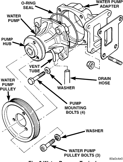
A quick test to determine if the pump is working is to check if the heater warms properly. A defective water pump will not be able to circulate heated coolant through the long heater hose to the heater core.
COOLANT
The cooling system is designed around the coolant. Coolant flows through the engine water jackets and water manifold absorbing heat produced during engine operation. The coolant carries heat to the radiator and heater core. Here it is transferred to the ambient air passing through the radiator and heater core fins.
LOW COOLANT LEVEL SENSOR
The low coolant level sensor checks for low coolant level in the coolant tank. A signal will be sent from this sensor to the powertrain control module (PCM). When the PCM determines low coolant level, the instrument panel mounted low coolant level warning lamp will be illuminated. The sensor is located on the bottom of the coolant tank. For information, refer to Group 8E, Instrument Panel and Gauges.
If this lamp is illuminated, it indicates the need for service.
DESCRIPTION AND OPERATION
THERMOSTAT
A pellet-type thermostat controls the operating temperature of the engine by controlling the amount of coolant flow to the radiator. The thermostat starts to open at 80°C (176°F). Above this temperature, coolant is allowed to flow to the radiator. This provides quick engine warmup and overall temperature control.
The same thermostat is used for winter and summer seasons. An engine should not be operated without a thermostat, except for servicing or testing. Operating without a thermostat causes other problems. These are: longer engine warmup time, unreliable warmup performance, increased exhaust emissions and crankcase condensation. This condensation can result in sludge formation.
CAUTION: Do not operate an engine without a thermostat, except for servicing or testing.
PRESSURE/VENT CAP
The pressure/vent cap is cam type cap. This cap releases excess pressure at some point within a range of 90 - 117 kPa (13 - 17 psi). The actual pressure relief point (in pounds) is labeled on top of the cap.
The cooling system will operate at pressures slightly above atmospheric pressure. This results in a higher coolant boiling point allowing increased radiator cooling capacity. The cap contains a springloaded pressure relief valve. This valve opens when system pressure reaches approximately 103 kPa (15 psi).
When the engine is cooling down, vacuum is formed within the cooling system. To prevent collapse of the radiator and coolant hoses from this vacuum, a vacuum valve is used within the cap. This valve prevents excessive pressure differences from occurring between the closed cooling system and the atmosphere. If the vacuum valve is stuck shut, the radiator and/or cooling system hoses
NOTE: Do not use any type of tool when tightening the cap. Hand tighten only (approximately 5 N·m or 44 in. lbs.) torque.
COOLANT PERFORMANCE
ETHYLENE-GLYCOL MIXTURES
The required ethylene-glycol (antifreeze) and water mixture depends upon the climate and vehicle operating conditions. The recommended mixture of 50/50 ethylene-glycol and water will provide protection against freezing to -37 deg. C (-35 deg. F). The antifreeze concentration must always be a minimum of 44 percent, year-round in all climates. If percentage is lower than 44 percent, engine parts may be eroded by cavitation, and cooling system components may be severely damaged by corrosion. Maximum protection against freezing is provided with a 68 percent antifreeze concentration, which prevents freezing down to -67.7 deg. C (-90 deg. F). A higher percentage will freeze at a warmer temperature. Also, a higher percentage of antifreeze can cause the engine to overheat because the specific heat of antifreeze is lower than that of water.
100 Percent Ethylene-Glycol—Should Not Be Used in Chrysler Vehicles
Use of 100 percent ethylene-glycol will cause formation of additive deposits in the system, as the corrosion inhibitive additives in ethylene-glycol require the presence of water to dissolve. The deposits act as insulation, causing temperatures to rise to as high as 149 deg. C (300) deg. F). This temperature is hot enough to melt plastic and soften solder. The increased temperature can result in engine detonation. In addition, 100 percent ethylene-glycol freezes at 22 deg. C (-8 deg. F).
Propylene-glycol Formulations—Should Not Be Used in Chrysler Vehicles
Propylene-glycol formulations do not meet Chrysler coolant specifications. It's overall effective temperature range is smaller than that of ethylene-glycol. The freeze point of 50/50 propylene-glycol and water is -32 deg. C (-26 deg. F). 5 deg. C higher than ethylene-glycol's freeze point. The boiling point (protection against summer boil-over) of propyleneglycol is 125 deg. C (257 deg. F ) at 96.5 kPa (14 psi), compared to 128 deg. C (263 deg. F) for ethylene-glycol. Use of propylene-glycol can result in boil-over or freeze-up in Chrysler vehicles, which are designed for ethylene-glycol. Propylene glycol also has poorer heat transfer characteristics than ethylene glycol. This can increase cylinder head temperatures under certain conditions.
Propylene-glycol/Ethylene-glycol Mixtures—Should Not Be Used in Chrysler Vehicles
Propylene-glycol/ethylene-glycol Mixtures can cause the destabilization of various corrosion inhibitors, causing damage to the various cooling system components. Also, once ethylene-glycol and propylene-glycol based coolants are mixed in the vehicle, conventional methods of determining freeze point will not be accurate. Both the refractive index and specific gravity differ between ethylene glycol and propylene glycol.
CAUTION: Richer antifreeze mixtures cannot be measured with normal field equipment and can cause problems associated with 100 percent ethylene-glycol.
COOLING SYSTEM HOSES
Rubber hoses route coolant to and from the radiator, water manifold and heater core. Models equipped with air conditioning have a heater water control (shut-off) valve. This is located in-line with the heater core inlet and outlet hoses. It controls coolant flow to the heater core when the air conditioning system is in operation.
Radiator lower hoses are spring-reinforced to prevent collapse from water pump suction at moderate and high engine speeds.
WARNING: CONSTANT TENSION HOSE CLAMPS ARE USED ON MOST COOLING SYSTEM HOSES. WHEN REMOVING OR INSTALLING, USE ONLY TOOLS DESIGNED FOR SERVICING THIS TYPE OF CLAMP (Fig. 4). ALWAYS WEAR SAFETY GLASSES WHEN SERVICING CONSTANT TENSION CLAMPS.
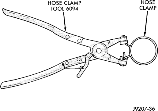
CAUTION: A number or letter is stamped into the tongue of constant tension clamps (Fig. 5). If replacement is necessary, use only an original equipment clamp with matching number or letter.
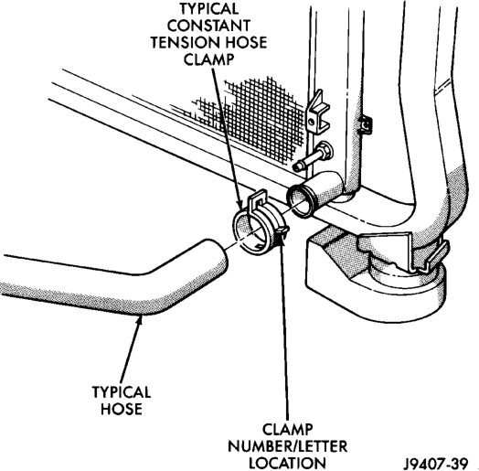
Inspect the hoses at regular intervals. Replace hoses that are cracked, feel brittle when squeezed, or swell excessively when the system is pressurized.
For all vehicles: In areas where specific routing clamps are not provided, be sure that hoses are positioned with sufficient clearance. Check clearance from exhaust manifolds and pipe, fan blades, drive belts and sway bars. Improperly positioned hoses can be damaged, resulting in coolant loss and engine overheating.
Ordinary worm gear type hose clamps (when equipped) can be removed with a straight screwdriver or a hex socket. To prevent damage to hoses or clamps, the hose clamps should be tightened to 4 N·m (34 in. lbs.) torque. Do not over tighten hose clamps.
When performing a hose inspection, inspect the radiator lower hose for proper position and condition of the internal spring.
VISCOUS FAN DRIVE
The thermal viscous fan drive (Fig. 6) is a siliconefluid-filled coupling. It connects the fan blade assembly to the fan pulley. The coupling allows the fan to be driven in a normal manner. This is done at low engine speeds while limiting the top speed of the fan to a predetermined maximum level at higher engine speeds. A bimetallic spring coil is located on the front face. This spring coil reacts to the temperature of the radiator discharge air. It engages the viscous fan drive for higher fan speed if the air temperature from the radiator rises above a certain point. Until additional engine cooling is necessary, the fan will remain at a reduced rpm regardless of engine speed.
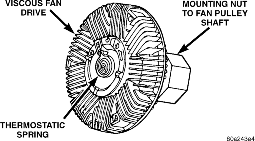
The viscous fan drive will only engage when sufficient heat is present. This is when the air flowing through the radiator core causes a reaction from the bimetallic coil. It then increases fan speed to provide the necessary additional engine cooling.
Once the engine has cooled, the radiator discharge temperature will drop. The bimetallic coil again reacts and the fan speed is reduced to the previous disengaged speed.
CAUTION: Some engines equipped with serpentine drive belts have reverse rotating fans and viscous fan drives. They are marked with the word REVERSE to designate their usage. Installation of the wrong fan or viscous fan drive can result in engine overheating.
NOISE
NOTE: It is normal for fan noise to be louder (roaring) when:
• The underhood temperature is above the engagement point for the viscous drive coupling. This may occur when ambient (outside air temperature) is very high.
• Engine loads and temperatures are high such as when towing a trailer.
• Cool silicone fluid within the fan drive unit is being redistributed back to its normal disengaged (warm) position. This can occur during the first 15 seconds to one minute after engine start-up on a cold engine.
LEAKS
Viscous fan drive operation is not affected by small oil stains near the drive bearing. If leakage appears excessive, replace the fan drive unit.
BELT TENSION
Correct accessory drive belt tension is required to be sure of optimum performance of belt driven engine accessories. If specified tension is not maintained, belt slippage may cause; engine overheating, lack of power steering assist, loss of air conditioning capacity, reduced generator output rate and greatly reduced belt life.
Initial belt adjustment is done with a adjustable tensioner pulley. After the initial adjustment is performed, an automatic belt tensioner is used to maintain correct belt tension at all times. Do not attempt to check belt tension with a belt tension gauge on vehicles equipped with an automatic belt tensioner. Refer to Automatic Belt Tensioner in this group.
AUTOMATIC BELT TENSIONER
Drive belt tension is controlled by a spring loaded automatic belt tensioner located below and to the front of the engine oil filter (Fig. 7). This tensioner is connected to a pivot bracket and a pulley (Fig. 7). The pivot bracket rotates on a pivot pin attached to the engine. Special machined washers with rubber o-rings (Fig. 7) are used at each side of the pivot bracket to help keep dirt and water away from the pivot pin.
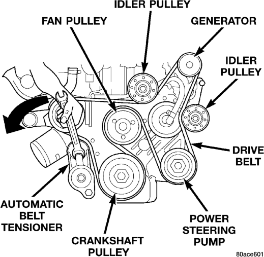
If a defective belt tensioner is suspected, a check of this pivot bracket and pivot pin should be made. Corrosion may have formed at the pin and may cause the pivot bracket to stick. Belt slippage will result.
WARNING: BECAUSE OF HIGH SPRING PRES- SURE, DO NOT ATTEMPT TO DISASSEMBLE THE AUTOMATIC BELT TENSIONER. UNIT IS SERVICED AS AN ASSEMBLY.
DIAGNOSIS AND TESTING
PRELIMINARY CHECKS
ENGINE COOLING SYSTEM OVERHEATING
Establish what driving conditions caused the complaint. Abnormal loads on the cooling system such as the following may be the cause:
(1) PROLONGED IDLE, VERY HIGH AMBIENT TEMPERATURE, SLIGHT TAIL WIND AT IDLE, SLOW TRAFFIC, TRAFFIC JAMS, HIGH SPEED OR STEEP GRADES.
Driving techniques that avoid overheating are: • Idle with A/C off when temperature gauge is at end of normal range.
• Increasing engine speed for more air flow is recommended.
(2) TRAILER TOWING: Consult Trailer Towing section of owners manual. Do not exceed limits.
(3) RECENT SERVICE OR ACCIDENT REPAIR: Determine if any recent service has been performed on vehicle that may effect cooling system. This may be:
• Engine adjustments (incorrect timing) • Slipping engine accessory drive belt • Brakes (possibly dragging) • Changed parts (incorrect water pump) •
Reconditioned radiator or cooling system refilling
(possibly under filled or air trapped in system).
NOTE: If investigation reveals none of the previous items as a cause for an engine overheating complaint, refer to following Cooling System Diagnosis charts.
These charts are to be used as a quick-reference only. Refer to the group text for information.
COOLING SYSTEM DIAGNOSIS-DIESEL
ENGINE
THERMOSTAT
DIAGNOSIS
Diesel engines, due to their inherent efficiency are slower to warm up than gasoline powered engines, and will operate at lower temperatures when the vehicle is unloaded. Because of this, lower temperature gauge readings for diesel versus gasoline engines may, at times be normal.
Typically, complaints of low engine coolant temperature are observed as low heater output when combined with cool or cold outside temperatures.
To help promote faster engine warm-up, an electric engine block heater must be used with cool or cold outside temperatures. This will help keep the engine coolant warm when the vehicle is parked. Use the block heater if the outside temperature is below 4°C (40°F). Do not use the block heater if the outside temperature is above 4°C (40°F).
TESTING
NOTE: The DRB scan tool cannot be used to monitor engine coolant temperature on the diesel engine.
(1) To determine if the thermostat is defective, it must be removed from the vehicle. Refer to Thermostats for removal and installation procedures.
(2) After the thermostat has been removed, examine the thermostat and inside of thermostat housing for contaminants. If contaminants are found, the thermostat may already be in a “stuck open” position. Flush the cooling system before replacing thermostat. Refer to Cooling System Cleaning/Reverse Flushing in this group for additional information. (3) Place the thermostat into a container filled with water.
(4) Place the container on a hot plate or other suitable heating device.
(5) Place a commercially available radiator thermometer into the water.
(6) Apply heat to the water while observing the thermostat and thermometer.
When the water temperature reaches 80°C (176°F)
(7)
the thermostat should start to open (valve will start to move). If the valve starts to move before this temperature is reached, it is opening too early. Replace thermostat. The thermostat should be fully open (valve will stop moving) at approximately 89°C (192°F). If the valve is still moving after the water temperature reaches this
(8) If the valve refuses to move at any time, replace thermostat.
VISCOUS FAN DRIVE
TESTING
If the fan assembly free-wheels without drag (the fan blades will revolve more than five turns when spun by hand), replace the fan drive. This spin test must be performed when the engine is cool.
The cooling system must be in good condition. This is checked prior to performing the following test. It also will ensure against excessively high coolant temperature.
WARNING: BE SURE OF ADEQUATE FAN BLADE CLEARANCE BEFORE DRILLING.
(1) Drill a 3.12-mm (1/8-in) diameter hole in the top center of the fan shroud.
(2) Obtain a dial thermometer with an 8 inch stem (or equivalent). It should have a range of -18°-to- 105°C (0°-to-220° F). Insert thermometer through the hole in the shroud. Be sure that there is adequate clearance from the fan blades.
(3) Block the air flow through the radiator. Secure a sheet of plastic in front of the radiator (or air conditioner condenser). Use tape at the top to secure the plastic and be sure that the air flow is blocked.
(4) Be sure that the air conditioner (if equipped) is turned off.
WARNING: USE EXTREME CAUTION WHEN THE ENGINE IS OPERATING. DO NOT STAND IN A DIRECT LINE WITH THE FAN. DO NOT PUT YOUR HANDS NEAR THE PULLEYS, BELTS OR FAN. DO NOT WEAR LOOSE CLOTHING.
(5)
Start the engine and operate at 2400 rpm. Within should be up to 83° C 200" F) Fan drive should have started to occur at between 82° to 91° C (180° to 195° F). Engagement is distinguishable by a definite increase in fan flow noise (roaring).
engagement
(6) When the air temperature reaches 93° C (200° F), remove the plastic sheet. Fan drive disengagement should have started to occur at between 57° to 79° C (135° to 175° F). A definite decrease of fan flow noise (roaring) should be noticed. If not, replace the defective viscous fan drive unit.
RADIATOR COOLANT FLOW CHECK
There is coolant flow all of the time through the coolant tank (bottle) before and after the thermostat opens. If you remove the vent valve and insert a temperature gauge through the opening, coolant will spill out of the system and the engine will not be filled with coolant up to the heads.
CAUTION: Major damage could happen if you run the engine in this condition.
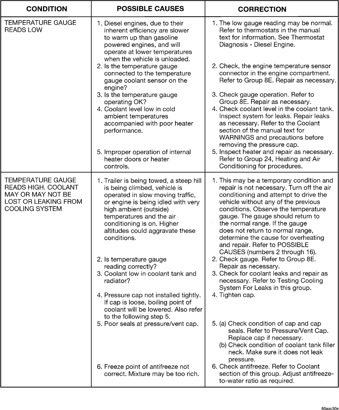
READS LOW inherent efficiency are slower Refer to thermostats in the manual
to warm up than gasoline text for information. See Thermostat
powered engines, and will Diagnosis - Diesel Engine.
operate at lower temperatures
when the vehicle is unloaded.
2. Is the temperature gauge 2. Check, the engine temperature sensor
connected to the temperature connector in the engine compartment.
gauge coolant sensor on the Refer to Group 8E. Repair as necessary.
engine?
3. Is the temperature gauge 3. Check gauge operation. Refer to
operating OK? Group 8E. Repair as necessary.
4. Coolant level low in cold 4. Check coolant level in the coolant tank.
ambient temperatures Inspect system for leaks. Repair leaks
accompanied with poor heater as necessary. Refer to the Coolant
performance. section of the manual text for
WARNINGS and precautions before
removing the pressure cap.
5. Improper operation of internal 5. Inspect heater and repair as necessary.
heater doors or heater Refer to Group 24, Heating and Air
controls. Conditioning for procedures.
TEMPERATURE GAUGE 1. Trailer is being towed, a steep hill | 1. This may be a temporary condition and
READS HIGH. COOLANT is being climbed, vehicle is repair is not necessary. Turn off the air
MAY OR MAY NOT BE operated in slow moving traffic, conditioning and attempt to drive the
LOST OR LEAKING FROM or engine is being idled with very vehicle without any of the previous
COOLING SYSTEM high ambient (outside) conditions. Observe the temperature
temperatures and the air gauge. The gauge should return to
conditioning is on. Higher the normal range. If the gauge
altitudes could aggravate these does not return to normal range,
conditions. determine the cause for overheating
and repair. Refer to POSSIBLE
CAUSES (numbers 2 through 16).
2. Ils temperature gauge 2. Check gauge. Refer to Group 8E.
reading correctly? Repair as necessary.
3. Coolant low in coolant tank and 3. Check for coolant leaks and repair as
radiator? necessary. Refer to Testing Cooling
System For Leaks in this group.
4. Pressure cap not installed tightly. | 4. Tighten cap.
If cap is loose, boiling point of
coolant will be lowered. Also refer
to the following step 5.
5. Poor seals at pressure/vent cap. 5. (a) Check condition of cap and cap
seals. Refer to Pressure/Vent Cap.
Replace cap if necessary.
(6) Check condition of coolant tank filler
neck. Make sure it does not leak
pressure.
6. Freeze point of antifreeze not 6. Check antifreeze. Refer to Coolant
correct. Mixture may be too rich. section of this group. Adjust antifreeze-
to-water ratio as required.
80aac30e
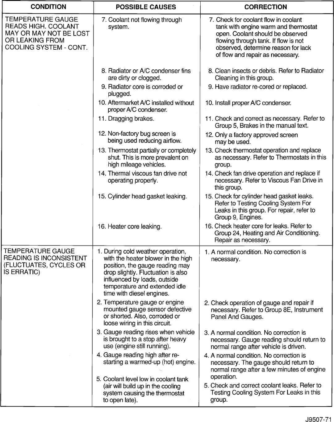
TEMPERATURE GAUGE 7. Coolant not flowing through 7. Check for coolant flow in coolant
READS HIGH. COOLANT system. tank with engine warm and thermostat
MAY OR MAY NOT BE LOST open. Coolant should be observed
OR LEAKING FROM flowing through tank. If flow is not
COOLING SYSTEM - CONT. observed, determine reason for lack
of flow and repair as necessary.
8. Radiator or A/C condenser fins 8. Clean insects or debris. Refer to Radiator
are dirty or clogged. Cleaning in this group.
9. Radiator core is corroded or 9. Have radiator re-cored or replaced.
plugged.
10. Aftermarket A/C installed without | 10. Install proper A/C condenser.
proper A/C condenser.
11. Dragging brakes. 11. Check and correct as necessary. Refer to
Group 5, Brakes in the manual text.
12. Non-factory bug screen is 12. Only a factory approved screen
being used reducing airflow. may be used.
13. Thermostat partially or completely | 13. Check thermostat operation and replace
shut. This is more prevalent on as necessary. Refer to Thermostats in this
high mileage vehicles. group.
14. Thermal viscous fan drive not 14. Check fan drive operation and replace if
operating properly. necessary. Refer to Viscous Fan Drive in
this group.
15. Cylinder head gasket leaking. 15. Check for cylinder head gasket leaks.
Refer to Testing Cooling System For
Leaks in this group. For repair, refer to
Group 9, Engines.
16. Heater core leaking. 16. Check heater core for leaks. Refer to
Group 24, Heating and Air Conditioning.
Repair as necessary.
TEMPERATURE GAUGE 1. During cold weather operation, 1. Anormal condition. No correction is
READING IS INCONSISTENT with the heater blower in the high necessary.
(FLUCTUATES, CYCLES OR position, the gauge reading may
IS ERRATIC) drop slightly. Fluctuation is also
influenced by loads, outside
temperature and extended idle
time with diesel engines.
2. Temperature gauge or engine 2. Check operation of gauge and repair if
mounted gauge sensor defective necessary. Refer to Group 8E, Instrument
or shorted. Also, corroded or Panel And Gauges.
loose wiring in this circuit.
3. Gauge reading rises when vehicle | 3. A normal condition. No correction is
is brought to a stop after heavy necessary. Gauge reading should return to
use (engine still running). normal range after vehicle is driven.
4. Gauge reading high after re- 4, A normal condition. No correction is
starting a warmed-up (hot) engine. necessary. The gauge should return to
~ normal range after a few minutes of engine
5. Coolant level low in coolant tank operation.
(air will build up in the cooling 5. Check and correct coolant leaks. Refer to
system causing the thermostat Testing Cooling System For Leaks in this
to open late). group.
J9507-71
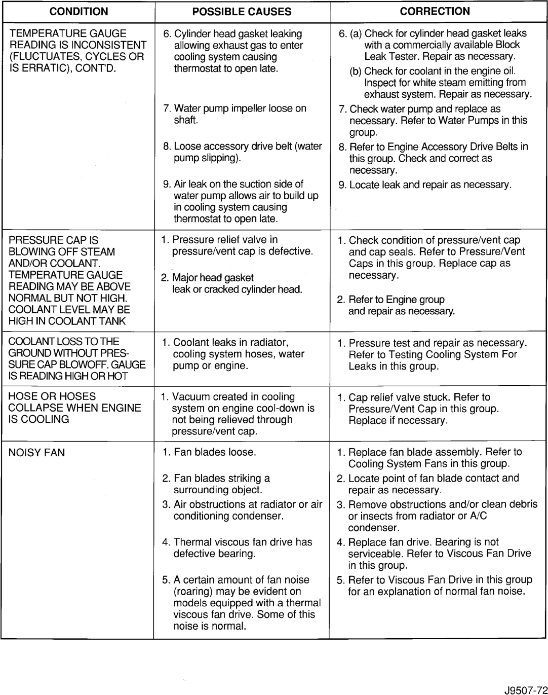
TEMPERATURE GAUGE 6. Cylinder head gasket leaking 6. (a) Check for cylinder head gasket leaks
READING IS INCONSISTENT allowing exhaust gas to enter with a commercially available Block
(FLUCTUATES, CYCLES OR cooling system causing Leak Tester. Repair as necessary.
IS ERRATIC), CONT'D. thermostat to open late. (b) Check for coolant in the engine oil.
Inspect for white steam emitting from
exhaust system. Repair as necessary.
7. Water pump impeller loose on 7. Check water pump and replace as
shaft. necessary. Refer to Water Pumps in this
group.
8. Loose accessory drive belt (water | 8. Refer to Engine Accessory Drive Belts in
pump slipping). this group. Check and correct as
necessary.
9. Air leak on the suction side of 9. Locate leak and repair as necessary.
water pump allows air to build up
in cooling system causing
thermostat to open late.
PRESSURE CAP IS 1. Pressure relief valve in 1. Check condition of pressure/vent cap
BLOWING OFF STEAM pressure/vent cap is defective. and cap seals. Refer to Pressure/Vent
AND/OR COOLANT. Caps in this group. Replace cap as
TEMPERATURE GAUGE 2. Major head gasket necessary.
READING MAY BE ABOVE leak or cracked cylinder head.
NORMAL BUT NOT HIGH. 2. Refer to Engine group
COOLANT LEVEL MAY BE and repair as necessary.
HIGH IN COOLANT TANK
COOLANT LOSS TO THE 1. Coolant leaks in radiator, 1. Pressure test and repair as necessary.
GROUND WITHOUT PRES- cooling system hoses, water Refer to Testing Cooling System For
SURE CAP BLOWOFF. GAUGE pump or engine. Leaks in this group.
IS READING HIGH OR HOT
HOSE OR HOSES 1. Vacuum created in cooling 1. Cap relief valve stuck. Refer to
COLLAPSE WHEN ENGINE system on engine cool-down is Pressure/Vent Cap in this group.
IS COOLING not being relieved through Replace if necessary.
pressure/vent cap.
NOISY FAN 1. Fan blades loose. 1. Replace fan blade assembly. Refer to
Cooling System Fans in this group.
2. Fan blades striking a 2. Locate point of fan blade contact and
surrounding object. repair as necessary.
3. Air obstructions at radiator or air | 3. Remove obstructions and/or clean debris
conditioning condenser. or insects from radiator or A/C
condenser.
4. Thermal viscous fan drive has 4. Replace fan drive. Bearing is not
defective bearing. serviceable. Refer to Viscous Fan Drive
in this group.
5. A certain amount of fan noise 5. Refer to Viscous Fan Drive in this group
(roaring) may be evident on for an explanation of normal fan noise.
models equipped with a thermal
viscous fan drive. Some of this
noise is normal.
J9507-72
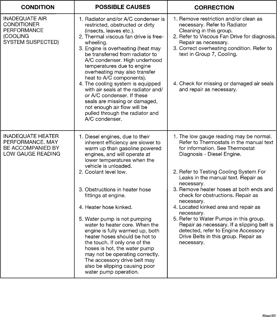
CONDITIONER restricted, obstructed or dirty necessary. Refer to Radiator
PERFORMANCE (insects, leaves etc.). Cleaning in this group.
(COOLING 2. Thermal viscous fan drive is free- | 2. Refer to Viscous Fan Drive for diagnosis.
SYSTEM SUSPECTED) wheeling. Repair as necessary.
3. Engine is overheating (heat may 3. Correct overheating condition. Refer to
be transferred from radiator to text in Group 7, Cooling.
A/C condenser. High underhood
temperatures due to engine
overheating may also transfer
heat to A/C components).
4. The cooling system is equipped 4. Check for missing or damaged air seals
with air seals at the radiator and/ and repair as necessary.
or A/C condenser. If these
seals are missing or damaged,
not enough air flow will be
pulled through the radiator and
A/C condenser.
INADEQUATE HEATER 1. Diesel engines, due to their 1. The low gauge reading may be normal.
PERFORMANCE. MAY inherent efficiency are slower to Refer to Thermostats in the manual text
BE ACCOMPANIED BY warm up than gasoline powered for information. See Thermostat
LOW GAUGE READING engines, and will operate at Diagnosis - Diesel Engine.
lower temperatures when the
vehicle is unloaded.
2. Coolant level low. 2. Refer to Testing Cooling System For
Leaks in the manual text. Repair as
necessary.
3. Obstructions in heater hose 3. Remove heater hoses at both ends and
fittings at engine. check for obstructions. Repair as
necessary.
4. Heater hose kinked. 4. Located kinked area and repair as
necessary.
5. Water pump is not pumping 5. Refer to Water Pumps in this group.
water to heater core. When the Repair as necessary. If a slipping belt is
engine is fully warmed up, both detected, refer to Engine Accessory
heater hoses should be hot to Drive Belts in this group. Repair as
the touch. If only one of the necessary.
hoses is hot, the water pump
may not be operating correctly.
The accessory drive belt may
also be slipping causing poor
water pump operation.
80aac30f