Body — 1998 Jeep Grand Cherokee ZJ Export Service Manual
Pages 1689–1742 · 54 pages · 4 words repaired
GENERAL INFORMATION
BASE COAT/CLEAR COAT FINISH . . . . . . . . . . . . 2 PAINT CODE . . . . . . . . . . . . . . . . . . . . . . . . . . . . 2 PAINTED SURFACE TOUCH-UP . . . . . . . . . . . . . 2
GENERAL INFORMATION
PAINT CODE
Exterior vehicle body colors are identified on the Body Code plate. The plate is located on the top, right side of the dash panel below the cowl grille in the engine compartment. Refer to the Introduction section at the front of this manual for body code plate description. The paint code is also identified on the Vehicle Safety Certification Label which is located on the drivers door shut face. The color names provided in the Paint and Trim Code Description chart are the color names used on most repair product containers.
BASE COAT/CLEAR COAT FINISH
On most vehicles a two-part paint application (base coat/clear coat) is used. Color paint that is applied to primer is called base coat. The clear coat protects the base coat from ultraviolet light and provides a durable high-gloss finish.
WET SANDING, BUFFING, AND POLISHING
Minor acid etching, orange peel, or smudging in clear coat or single-stage finishes can be reduced with light wet sanding, hand buffing, and polishing. If the finish has been wet sanded in the past, it cannot be repeated. Wet sanding operation should be performed by a trained automotive paint technician.
CAUTION: Do not remove clear coat finish, if equipped. Base coat paint must retain clear coat for durability.
PAINT
INDEX
page page
WET SANDING, BUFFING, AND POLISHING . . . . 2 SPECIFICATIONS
AFTER MARKET PAINT REPAIR PRODUCTS . . . 3
PAINTED SURFACE TOUCH-UP
When a painted metal surface has been scratched or chipped, it should be touched-up as soon as possible to avoid corrosion. For best results, use Mopart Scratch Filler/Primer, Touch-Up Paints and Clear Top Coat. Refer to Introduction group of this manual for Body Code Plate information.
TOUCH-UP PROCEDURE
(1) Scrape loose paint and corrosion from inside scratch or chip.
(2) Clean affected area with Mopart Tar/Road Oil Remover, and allow to dry.
(3) Fill the inside of the scratch or chip with a coat of filler/primer. Do not overlap primer onto good surface finish. The applicator brush should be wet enough to puddle-fill the defect without running. Do not stroke brush applicator on body surface. Allow the filler/primer to dry hard.
(4) Cover the filler/primer with color touch-up paint. Do not overlap touch-up color onto the original color coat around the scratch or chip. Butt the new color to the original color, if possible. Do not stroke applicator brush on body surface. Allow touch-up paint to dry hard.
(5) On vehicles without clear coat, the touch-up color can be lightly wet sanded (1500 grit) and polished with rubbing compound. (6) On vehicles with clear coat, apply clear top coat to touch-up paint with the same technique as described in Step 4. Allow clear top coat to dry hard. If desired, Step 5 can be performed on clear top coat.
SPECIFICATIONS
AFTER MARKET PAINT REPAIR PRODUCTS
EXTERIOR COLOR
CHRY CODE
EXTERIOR
COLOR
*
Dark Rosewood
Flame Red Clear
Deep Slate Pearl
Char Gold II Satin
Light Driftwood
Forest Green Pearl
Deep Amethyst
Bright Metallic
Black Clear Coat DX8 9700 15214 99 34858 90-5950 CHA85:DX8
Taupe Frost Pearl
Stone White Clear
AKZO NOBEL SIKKENS
PPG BASF DuPONT SHERWIN- WILLIAMS
Pearl Coat REG 27558 25041 B9519 50266 CHA95:REG
Coat PR4 4679 23043 B9326 46916 CHA93:PR4
Coat VAW 5292 27166 B9774 54118 CHA97:VAW
Glow RJ7 35748 25037 B9532 50278 CHA95:RJ7
Satin Glow MFA 4569 22110 B9623 46579 CHA92:MFA
Coat SG8 47439 26078 B9609 51062 CHA95:SG8
Pearl Coat TCN 5246 27038 B9736 52026 CHA97:TCN
Clear Coat MS4 4820 24082 B9642 48823 CHA94:MS4
Coat TTK 5244 27040 B9750 52567 CHA97:TTK
Coat SW1 83542 26089 B9622 51540 CHA96:SW1
CLADDING COLOR
CHRY CODE
CLADDING
COLOR
*
Medium Driftwood MFD 27360 23054 C9321 48024 CHA93:MFD
Dark Rosewood REG 4966 25041 B9519 50266 CHAREGM
Deep Hunter Green SG8 47439 26078 B9609 51062 CHASG8M
Deep Amethyst TCN 5246 27038 B9736 52026 CHA97:TCN
Dark Neutral Gray HS5 34349 20215 C8923 40392 CHA90:HS5
Bright Platinum MS4 4820 24082 B9462 48823 CHAMS4M
Char Gold II Satin
Stone White SW1 83542 26089 B9622 51539 CHASW1M
NOTE: *Herberts Standox and Spies Hecker use the Chrysler paint code as listed on the Body Code Plate and the Vehicle Safety Certification label.
INTERIOR COLOR
INTERIOR
COLOR
Saddle/ Moss
TJ N/A 26121 25069
Green (RT6/RJ4)
AKZO NOBEL SIKKENS
SHER- WIN-WIL-
PPG BASF DuPONT
LIAMS
Flame Red PR4 4679 23043 B9326 46916 CHAPR4M
Black DX8 9700 15214 F0204 34858 90-5950 CHADX8M
Deep Slate VAW 5292 27166 B9774 54118 CHA97:VAW
Glow RJ7 4975 25037 B9532 50278 CHA95:RJ7
Taupe Frost TTK 5244 27040 B9750 52567 CHA97:TTK
AKZO NOBEL SIKKENS
CHRY CODE PPG BASF DuPONT SHERWIN- WILLIAMS
Agate AZ 9856/2-1461 22135 C9208 45994 CHALAZI
Mist Gray C3 35799/2-1576 25065 C9507 50508 CHARC3I
Saddle T6 27917/2-1594 26121 C9603 51541 CHART6I
C9604 C9513 51542 50512
CHART6I/
CHARJ4I
DESCRIPTION AND OPERATION
SAFETY PRECAUTIONS . . . . . . . . . . . . . . . . . . . 5 REMOVAL AND INSTALLATION
LIFTGATE GLASS . . . . . . . . . . . . . . . . . . . . . . . . 8
DESCRIPTION AND OPERATION
SAFETY PRECAUTIONS
WARNING: DO NOT OPERATE THE VEHICLE WITHIN 24 HOURS OF WINDSHIELD INSTALLATION. IT TAKES AT LEAST 24 HOURS FOR URETHANE ADHESIVE TO CURE. IF IT IS NOT CURED, THE WINDSHIELD MAY NOT PERFORM PROPERLY IN AN ACCIDENT.
URETHANE ADHESIVES ARE APPLIED AS A SYS- TEM. USE GLASS CLEANER, GLASS PREP SOL- VENT, GLASS PRIMER, PVC (VINYL) PRIMER AND PINCHWELD (FENCE) PRIMER PROVIDED BY THE ADHESIVE MANUFACTURER. IF NOT, STRUCTURAL INTEGRITY COULD BE COMPROMISED.
CHRYSLER DOES NOT RECOMMEND GLASS ADHESIVE BY BRAND. TECHNICIANS SHOULD REVIEW PRODUCT LABELS AND TECHNICAL DATA SHEETS, AND USE ONLY ADHESIVES THAT THEIR MANUFACTURES WARRANT WILL RESTORE A VEHICLE TO THE REQUIREMENTS OF FMVSS 212. TECHNICIANS SHOULD ALSO INSURE THAT PRIM- ERS AND CLEANERS ARE COMPATIBLE WITH THE PARTICULAR ADHESIVE USED.
BE SURE TO REFER TO THE URETHANE MANU- FACTURER'S DIRECTIONS FOR CURING TIME SPECIFICATIONS, AND DO NOT USE ADHESIVE AFTER ITS EXPIRATION DATE.
VAPORS THAT ARE EMITTED FROM THE URE- THANE ADHESIVE OR PRIMER COULD CAUSE PERSONAL INJURY. USE THEM IN A WELL-VENTI- LATED AREA.
SKIN CONTACT WITH URETHANE ADHESIVE SHOULD BE AVOIDED. PERSONAL INJURY MAY RESULT.
ALWAYS WEAR EYE AND HAND PROTECTION WHEN WORKING WITH GLASS.
CAUTION: Protect all painted and trimmed surfaces from coming in contact with urethane or primers.
STATIONARY GLASS
INDEX
page page
QUARTER WINDOW GLASS . . . . . . . . . . . . . . . . 7 WINDSHIELD . . . . . . . . . . . . . . . . . . . . . . . . . . . . 5
Be careful not to damage painted surfaces when removing moldings or cutting urethane around windshield.
It is difficult to salvage a windshield during the removal operation. The windshield is part of the structural support for the roof. The urethane bonding used to secure the windshield to the fence is difficult to cut or clean from any surface. If the moldings are set in urethane, it would also be unlikely they could be salvaged. Before removing the windshield, check the availability of the windshield and moldings from the parts supplier.
REMOVAL AND INSTALLATION
WINDSHIELD
REMOVAL
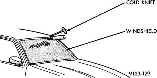
(1) Remove inside rear view mirror. (2) Remove cowl cover. (3) Remove screws attaching windshield side molding to A-pillar (Fig. 1). (4) Remove upper windshield molding. (5) Cut urethane bonding from around windshield using a suitable sharp cold knife. A pneumatic cutting device can be used if available (Fig. 2).
(6) Separate windshield from vehicle.
INSTALLATION
WARNING: REVIEW ALL WARNINGS AND CAU- TIONS IN THIS GROUP BEFORE PRECEDING WITH INSTALLATION.
CAUTION: Open a window before installing windshield. This will avoid pressurizing the passenger compartment. If a door or liftgate is slammed before urethane is cured, water leaks can result.
The windshield fence should be cleaned of old urethane bonding material. Support spacers should be
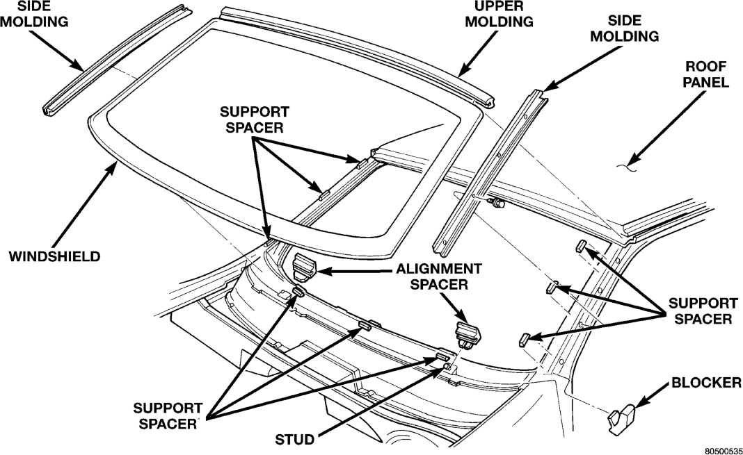
cleaned and properly installed on weld studs or repair screws at bottom of windshield opening.
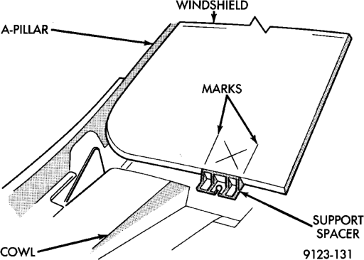
(1) Place replacement windshield into windshield opening. Position glass in the center of the opening against the support spacers. Mark the glass at the support spacers with a grease pencil or masking tape and ink pen to use as a reference for installation. Remove replacement windshield from windshield opening (Fig. 3).
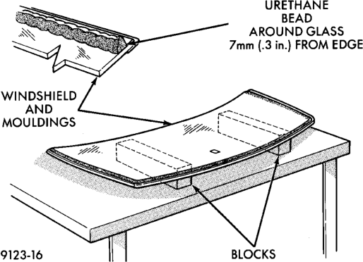
(2) Position the windshield inside up on a suitable work surface with two padded, wood 10 cm by 10 cm by 50 cm (4 in. by 4 in. by 20 in.) blocks, placed parallel 75 cm (2.5 ft.) apart (Fig. 4).
(3) Clean inside of windshield with Mopar Glass Cleaner and lint-free cloth.
(4) Apply clear glass primer 25 mm (1 in.) wide around edge of windshield. Wipe with clean/dry lintfree cloth.
(5) Apply black-out primer 15 mm (.75 in.) wide on top and sides of windshield and 25 mm (1 in.) on bottom of windshield. Allow at least three minutes drying time. (6) Position windshield spacers on lower fence above support spacers at the edge of the windshield opening (Fig. 1).
(7) Apply a 10 mm (0.4 in.) bead of urethane around perimeter of windshield along the inside of the moldings. Apply two beads along the bottom edge.
(8) Install upper molding onto windshield. (9) Apply fence primer around the perimeter of the windshield opening fence. Allow at least 18 minutes drying time.
(10) With aid of a helper, position windshield over windshield opening. Align reference marks at bottom of windshield to support spacers.
(11) Slowly lower windshield glass to windshield opening fence. Guide top molding into proper position if necessary. Push windshield inward to fence spacers at bottom and until top molding is flush to roof line.
(12) Clean excess urethane from exterior with Mopar Super Clean or equivalent.
(13) Install windshield side moldings. (14) Install cowl cover and wipers. (15) Install inside rear view mirror. (16) After urethane has cured, water test windshield to verify repair.
Spacers
QUARTER WINDOW GLASS
REMOVAL
(1) Cut urethane bonding from around quarter window glass using a suitable sharp cold knife. A pneumatic cutting device can be used if available.
(2) Separate glass from vehicle.
INSTALLATION
CAUTION: Open a window before installing glass. This will avoid pressurizing the passenger compartment. If a door or liftgate is slammed before urethane is cured, water leaks can result.
The window opening fence should be cleaned of old urethane bonding material.
(1) Clean inside of glass with Mopar Glass Cleaner and lint-free cloth.
(2) Apply PVC (vinyl) primer 25 mm (1 in.) wide around edge of glass. Wipe with clean/dry lint-free cloth.
(3) Apply fence primer around edge of fence. Allow at least eighteen minutes drying time.
(4) Apply a 10 mm (0.4 in.) bead of urethane around window vinyl border location.
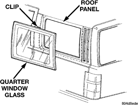
Position glass into window opening and lock clips into place (Fig. 5).
LIFTGATE GLASS
REMOVAL
(1) Cut urethane bonding from around liftgate glass using a suitable sharp cold knife. A pneumatic cutting device can be used if available.
(2) Separate glass from vehicle.
INSTALLATION
CAUTION: Open a window before installing glass. This will avoid pressurizing the passenger compartment. If a door or liftgate is slammed before urethane is cured, water leaks can result.
The window opening fence should be cleaned of old urethane bonding material.
(1) Clean inside of glass with Mopar Glass Cleaner and lint-free cloth.
(2) Apply PVC (vinyl) primer 25 mm (1 in.) wide around edge of glass. Wipe with clean/dry lint-free cloth.
(3) Apply fence primer around edge of fence. Allow at least eighteen minutes drying time.
(4) Apply a 10 mm (0.4 in.) bead of urethane around window vinyl border location.
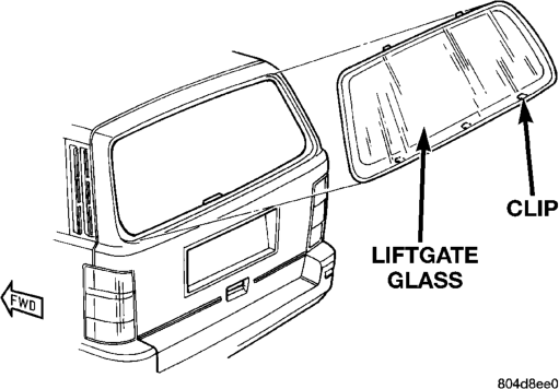
Position glass into window opening and lock clips into place (Fig. 6).
GENERAL INFORMATION
GENERAL INFORMATION . . . . . . . . . . . . . . . . . . 9 REMOVAL AND INSTALLATION
DRAIN CHANNEL . . . . . . . . . . . . . . . . . . . . . . . . 13 DRAIN TUBE . . . . . . . . . . . . . . . . . . . . . . . . . . . 13 DRIVE CABLE LOCATORS . . . . . . . . . . . . . . . . . 13 DRIVE CABLES . . . . . . . . . . . . . . . . . . . . . . . . . 14 GLASS PANEL . . . . . . . . . . . . . . . . . . . . . . . . . . 12
GENERAL INFORMATION
GENERAL INFORMATION
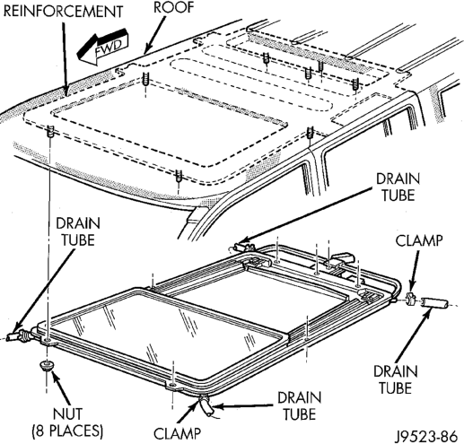
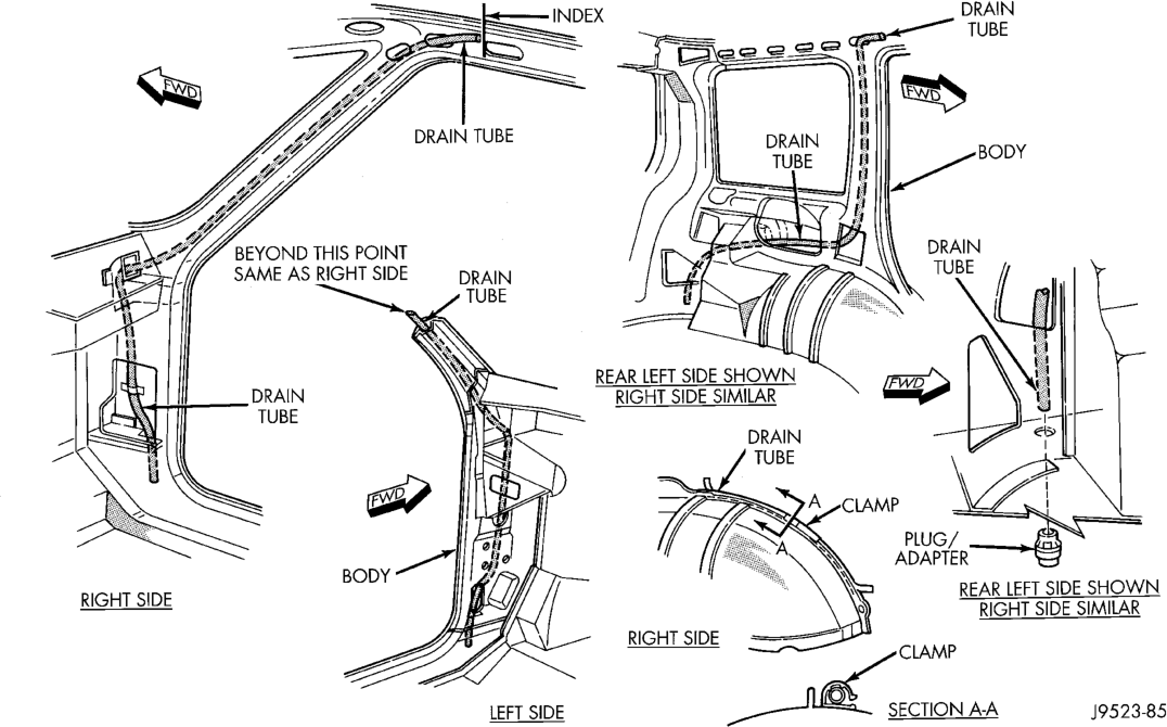
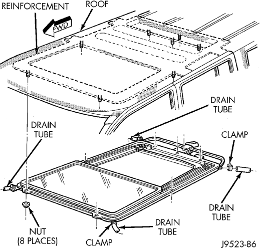
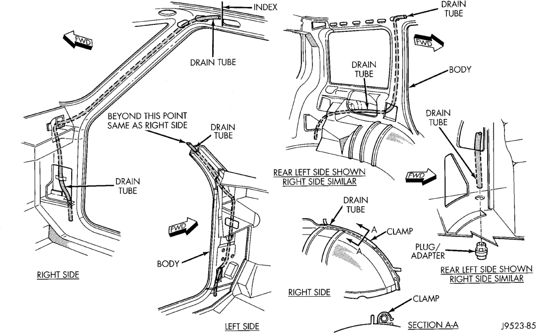
All sunroofs are equipped with drain tubes (Fig. 1) and (Fig. 2). The drain tubes must be kept open to prevent water from entering passenger compartment. When servicing separate components, refer to the Sunroof Component view (Fig. 3) for part description.
POWER SUNROOF
INDEX
page page
GUIDE ASSEMBLY . . . . . . . . . . . . . . . . . . . . . . . 15 MOTOR AND DRIVE GEARS . . . . . . . . . . . . . . . 13 SUNROOF ADJUSTMENT BRACKET . . . . . . . . . 13 SUNSHADE . . . . . . . . . . . . . . . . . . . . . . . . . . . . 15 WIND DEFLECTOR . . . . . . . . . . . . . . . . . . . . . . 12 ADJUSTMENTS
GLASS PANEL VERTICAL HEIGHT
ADJUSTMENT . . . . . . . . . . . . . . . . . . . . . . . . . 16

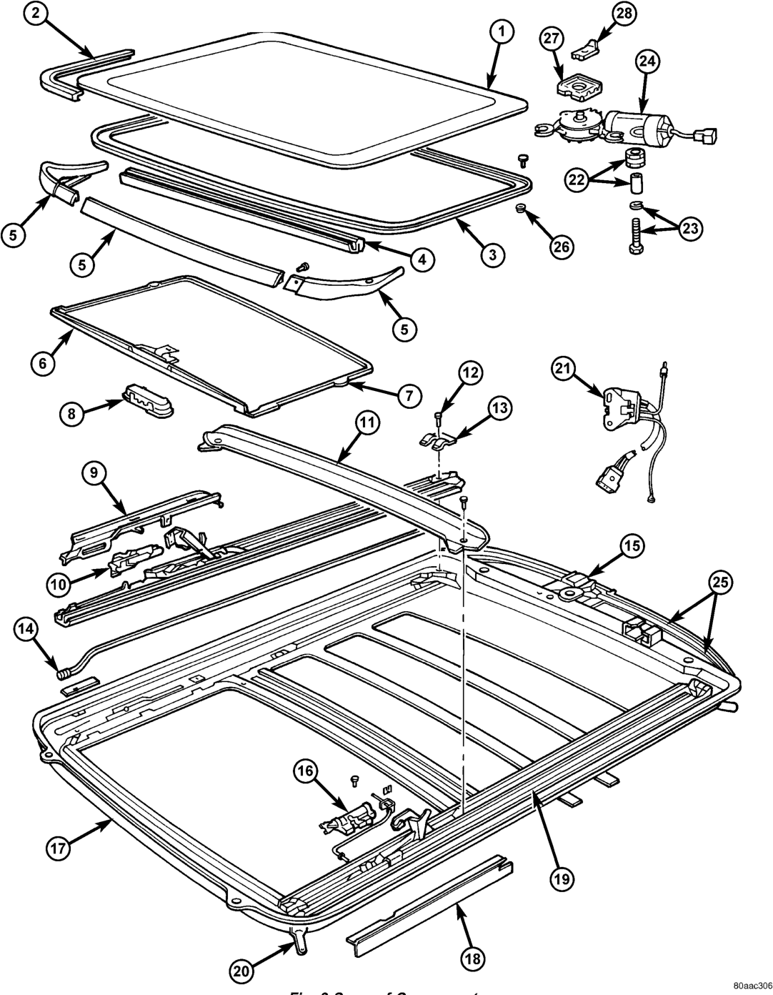

1 Glass Panel 15 Cable & Bracket
2 Seal 16 Locator
3 Reinforcement 17 Tray
4 Support 18 Cover
5 Deflector 19 Track (R) or (L)
6 Sunshade 20 Drain Hose
7 Clip 21 Relay
8 Handle 22 Spacer
9 Bracket (R) or (L) 23 Screw & Washer
10 Locator 24 Motor
11 Drain Channel 25 Cables
12 Screw 26 Nut
13 Bracket 27 Bracket
14 Seal 28 Bracket
REMOVAL AND INSTALLATION
WIND DEFLECTOR
REMOVAL
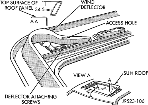
(1) Open sun roof glass panel. (2) Remove screws holding wind deflector to sun roof unit side rail (Fig. 4).
(3) Separate wind deflector from vehicle.
INSTALLATION
(1) Reverse preceding operation.
GLASS PANEL
REMOVAL
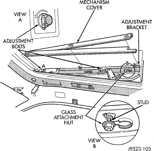
(1) Position glass to vent position. (2) Remove wind deflector mechanism covers (Fig. 5).
Sunroof Components
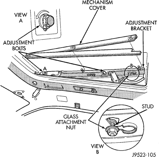
(3) Position sunshade full rearward. (4) Loosen nuts holding glass panel to side adjustment brackets show in View B (Fig. 5).
(5) Slide glass panel rearward 12mm (0.5in.) and separate glass from sunroof unit.
INSTALLATION
(1) Position glass panel in opening with logo rearward and slide panel forward 12 mm (0.5in.).
(2) Verify that attaching nuts are below top surface of glass adjustment brackets.
(3) Close sunroof to center glass panel in roof opening.
(4) Tighten center nuts to hold adjustment. (5) Open glass to vent position and tighten nuts to 8 N·m (70.8 in. lbs.).
(6) Close glass and check alignment. (7) Locate glass to vent position. (8) Install mechanism covers.
SUNROOF ADJUSTMENT BRACKET
REMOVAL
(1) Remove wind deflector, mechanism covers and glass panel.
(2) Move glass carriage to vent position and remove rearward adjustment bolt from adjustment bracket.
(3) Lift rear of adjustment bracket to highest vertical position and disengage front of bracket from unit (Fig. 5).
INSTALLATION
(1) Reverse the preceding operation. Adjust glass as necessary.
DRAIN CHANNEL
REMOVAL
(1) Move glass to vent position. (2) Remove mechanism covers and glass panel. (3) Remove screws holding drain channel to support frame.
INSTALLATION
(1) Reverse preceding operation.
DRAIN TUBE
REMOVAL
(1) Remove the headliner to access clamps attaching drain tube to sunroof. (2) Disengage clamps attaching drain tube to sunroof (Fig. 6).
(3) Tape the end of the old drain tube to the new drain tube. Ensure that the tape build up on the tube ends is not excessive.
(4) Remove front/rear trim panels as necessary to disengage clamps securing drain tube to body (Fig. 7).
(5) Remove the drain tube plug from the underside of the vehicle.
(6) From the underside of the vehicle carefully, pull/route the drain tube through the body panel. Applying a soapy water solution to the new tube may aid in this procedure.
INSTALLATION
(1) Install the plug adapter to the bottom of the drain tube.
(2) Engage clamps securing drain tube to body. (3) Install front/rear trim panels as necessary. (4) Install drain tube to sunroof and engage clamp. (5) Install the headliner.
DRIVE CABLE LOCATORS
REMOVAL
(1) Position glass 19 mm (0.75 in.) until rearward cable locator is visible.
(2) Remove screws holding drive cable locator to unit.
(3) Remove travel limiting micro switch grommet and disconnect wire connector.
(4) Insert a small screwdriver under rear edge of locator and pry locator from track (Fig. 8).
INSTALLATION
(1) Reverse preceding operation. The small outboard lip underneath cable locator slips under bottom slot on guide track. After locator is seated, install screws.
MOTOR AND DRIVE GEARS
REMOVAL
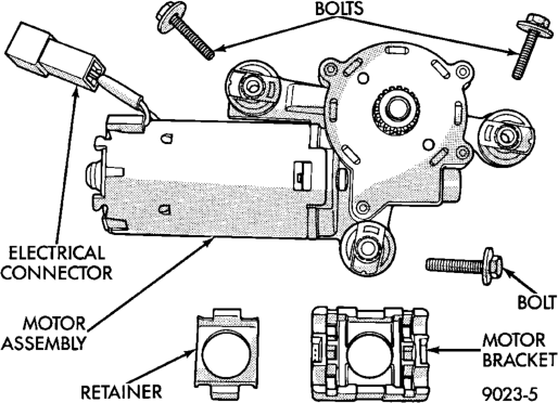
(1) Open sunroof to vent position. (2) Remove headlining. (3) Remove bolts holding sunroof motor to motor bracket.
(4) Disconnect wire connector. (5) Separate motor and drive gear from drive cables (Fig. 9).
Fig. 7 Drain Tube Clamps
INSTALLATION
(1) Verify that sunroof is in vent position. Push mechanism forward on both sides to align drive cables.
(2) Engage drive gears onto drive cables. (3) Install motor and drive gear screws and tighten to 5 N·m (44in-lbs.).
(4) Install headlining.
DRIVE CABLES
REMOVAL
(1) Open sunroof to vent position.
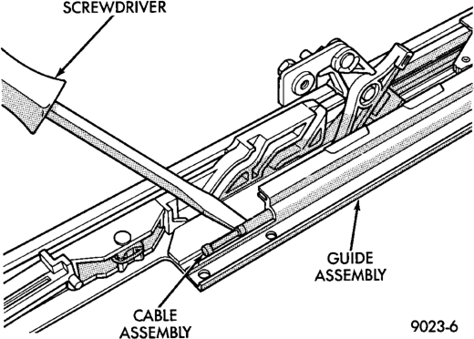
(2) Remove headlining, wind deflector, mechanism covers, glass panel, side glass adjustment brackets, motor and drive cable locators.
(3) Lift cable out of cable retainer and pull forward. Separate cable from assembly (Fig. 10).
INSTALLATION
Verify sunroof is in vent position. Push mechanism forward on both sides to align drive cables. Reverse the preceding operation.
SUNSHADE
REMOVAL
(1) Remove wind deflector, mechanism covers and glass panel.
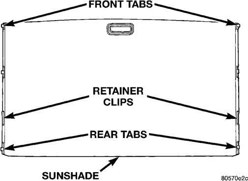
(2) Position system to full rearward position. (3) Slide sunshade panel full forward and release the front tabs from track assembly.
(4) Pull front and rear retaining clips inboard and lift sunshade out (Fig. 11).
INSTALLATION
(1) Reverse removal procedure.
GUIDE ASSEMBLY
REMOVAL
(1) Remove wind deflector, mechanism covers, glass panel, drain channel, sunshade and drive cable locator as necessary.
(2) Move glass carriage to vent position. (3) Remove front slide from guide assembly. (4) Remove screws holding front and center guide track to unit.
(5) Pull cable out of groove for cable end. (6) Pull guide outward to release from housing. Separate rear end of guide from clips. Slide guide out of unit (Fig. 12).
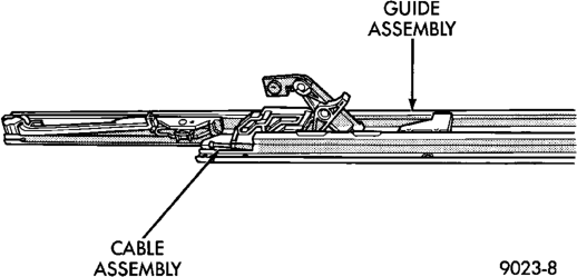
INSTALLATION
(1) Install guide cable into rear of guide assembly. (2) Install guide assembly at an angle so the rear portion slips under finger clips at rear of module housing.
(3) Place cable in groove of cable holder. (4) Install screws in track assembly. (5) Install wind deflector, mechanism covers, glass panel, drain channel, sunshade and drive cable locator as necessary.
ADJUSTMENTS
GLASS PANEL VERTICAL HEIGHT ADJUSTMENT
(1) Open glass to vent position. (2) Slide upper half of mechanism covers rearward until clips disengage and separate covers from vehicle (Fig. 13).
(3) Close glass panel. Separately loosen adjusting bolts shown in View A (Fig. 13) and individually adjust the corners of the glass.
(4) Adjust front of glass panel to 1.0 mm (0.040 in.) below top surface of roof panel. (5) Adjust rear of glass to 1.0 mm (0.040 in.) above top surface of roof panel.
(6) Tighten adjustment bolts and install covers.
REMOVAL AND INSTALLATION
BUCKET SEAT BACK COVER . . . . . . . . . . . . . . 17 BUCKET SEAT BACK . . . . . . . . . . . . . . . . . . . . . 17 BUCKET SEAT CUSHION COVER . . . . . . . . . . . 18
REMOVAL AND INSTALLATION
BUCKET SEAT BACK
REMOVAL
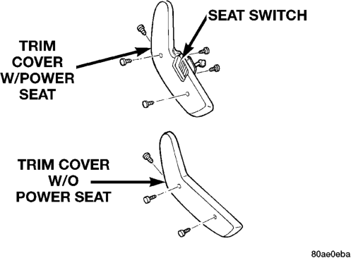
(1) Position seat back into full recline. (2) Remove seat cushion outboard trim cover (Fig. 1).
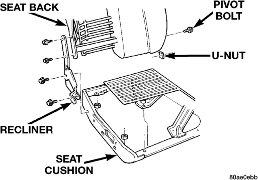
(3) Remove bolts attaching recliner to seat cushion frame (Fig. 2).
(4) Remove inboard pivot bolt. (5) Disengage electrical connectors for power lumbar, power recliner and seat heater element, if equipped.
(6) Separate seat back from vehicle.
INSTALLATION
(1) Position seat back in vehicle. (2) Engage electrical connectors for power lumbar, power recliner and seat heater element, if equipped.
(3) Install inboard pivot bolt. Tighten bolt to 40 N·m (29 ft. lbs.) torque.
(4) Install bolts attaching recliner to seat cushion frame. Tighten bolts to 28 N·m (20 ft. lbs.) torque.
(5) Install seat cushion outboard trim cover.
SEATS
INDEX
page page
BUCKET SEAT TRACK . . . . . . . . . . . . . . . . . . . . 19 LUMBAR SUPPORT . . . . . . . . . . . . . . . . . . . . . . 18 REAR SEAT BACK COVER . . . . . . . . . . . . . . . . 20 REAR SEAT CUSHION COVER . . . . . . . . . . . . . 20
BUCKET SEAT BACK COVER
REMOVAL
(1) Remove head restraint. (2) Remove seat back. (3) Unfasten seat back cover zipper. (4) Route zipper over power recliner motor, if equipped.
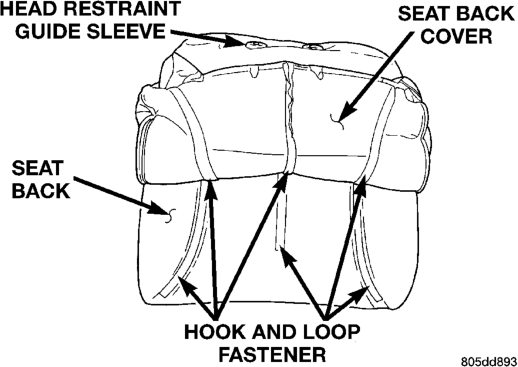
(5) Slide hand between the face of the seat back cushion and the cushion cover and carefully separate hook and loop fastener (Fig. 3).
(6) Roll cover upward to top of seat back. (7) Carefully slide cover over head restraint guide sleeves.
(8) Separate cover from seat back.
INSTALLATION
(1) Position cover at the top of seat back. (2) Carefully slide cover over head restraint guide sleeves.
(3) Roll cover downward. (4) Route zipper over power recliner motor, if equipped.
(5) Fasten seat back cover zipper. (6) Install seat back. (7) Install head restraint.
LUMBAR SUPPORT
REMOVAL
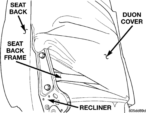
(1) Remove seat back. (2) Remove seat back cover. (3) Slide Duont cover upward to access bolts attaching recliner to seat back frame (Fig. 4) and remove recliner.
(4) Disengage hog rings at base of seat back. (5) Slide seat back frame out of seat back foam cushion.
(6) Remove Duon cover.
INSTALLATION
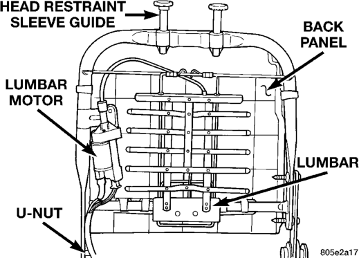
(1) Transfer components (Fig. 5): • Back panel. • Head restraint sleeves. • U-nut on inboard pivot location. (2) Install recliner. Tighten to 28 N·m (20 ft. lbs.) torque.
(3) Slide on Duon cover. (4) Slide on seat back foam cushion
(5) Install hog rings at seat back base. (6) Install seat back cover. (7) Route lumbar and heater harness, if equipped.
BUCKET SEAT CUSHION COVER
REMOVAL
(1) Remove seat from vehicle. (2) Remove seat back. (3) Using a trim stick, carefully pry knobs from seat function switches, if equipped.
(4) Remove screws attaching seat function switch to seat trim panel.
(5) Disengage J-strap attaching seat cover to front of seat cushion frame.
(6) Using a trim stick or small flat blade, disengage clips attaching seat cover to each side of seat cushion frame.
(7) Disengage hog rings attaching seat cover to rear of seat cushion frame.
(8) Route seat function switches through access hole on outboard side of seat cushion, if equipped.
(9) Disengage seat cushion heater element connector, if equipped.
(10) Slide hand between seat cushion cover and seat cushion. Carefully separate hook and loop fastener (Fig. 6).
(11) Separate seat cushion cover from seat cushion.
INSTALLATION
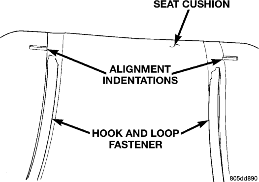
(1) Position seat cover on cushion. (2) Align seat cover with cushion alignment indentations (Fig. 7).
(3) Engage seat cushion heater element connector, if equipped. (4) Route seat function switches through access hole on outboard side of seat cushion, if equipped.
(5) Engage J-strap attaching seat cover to front of seat cushion frame.
(6) Engage hog rings attaching seat cover to rear of seat cushion frame.
(7) Engage clips attaching seat cover to each side of seat cushion frame.
(8) Install screws attaching seat function switch to seat trim panel.
(9) Install seat back. (10) Position knobs onto seat function switches and press into place.
(11) Install seat.
BUCKET SEAT TRACK
REMOVAL
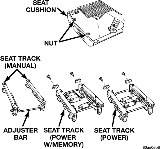
(1) Remove seat. (2) Remove nuts attaching seat track to seat cushion frame (Fig. 8). (3) Disengage seat memory module connector, if equipped.
(4) Separate seat track from seat cushion frame.
INSTALLATION
(1) Transfer seat memory module, if equipped. (2) Position seat track on seat cushion frame. (3) Engage seat memory module connector, if equipped.
(4) Install nuts attaching seat track to seat cushion frame. Tighten nuts to 20 N·m (15 ft. lbs.) torque.
REAR SEAT BACK COVER
REMOVAL
(1) Remove seatback from vehicle. If necessary, refer to removal procedure.
(2) Remove headrest. Twist knob under headrest and pull up and out of cylinders in seatback.
(3) Unfasten zipper (Fig. 9) on trim cover. and peel cover off pad by turning inside-out.
(4) If necessary, headrest cylinders may be removed from seatback frame. Squeeze locking tabs on cylinder and slide cylinder upward and remove from frame bracket.
INSTALLATION
Reverse removal procedure.
REAR SEAT CUSHION COVER
REMOVAL
(1) Remove seat cushion from vehicle. If necessary, refer to removal procedure.
(2) Using a trim tool, disengage seat cover retainers that hold trim cover to flange of cushion pan.
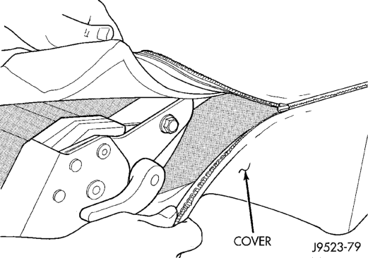
(3) Remove pad and cover from pan. (4) Separate cover from pad by turning inside-out and opening hogrings along 3 grooves in pad.
INSTALLATION
Reverse removal procedure.
DIAGNOSIS AND TESTING
UNIVERSAL TRANSMITTER . . . . . . . . . . . . . . . . 23 WATER LEAKS . . . . . . . . . . . . . . . . . . . . . . . . . . 22 WIND NOISE . . . . . . . . . . . . . . . . . . . . . . . . . . . 23 SERVICE PROCEDURES
BODY LUBRICATION . . . . . . . . . . . . . . . . . . . . . 23 REMOVAL AND INSTALLATION
A-PILLAR TRIM . . . . . . . . . . . . . . . . . . . . . . . . . 39 ASSIST HANDLE . . . . . . . . . . . . . . . . . . . . . . . . 39 BODY SIDE CLADDING . . . . . . . . . . . . . . . . . . . 38 BODY STRIPES/DECALS . . . . . . . . . . . . . . . . . . 27 C-PILLAR TRIM . . . . . . . . . . . . . . . . . . . . . . . . . 41 CARGO CARPET/MAT . . . . . . . . . . . . . . . . . . . . 44 COWL GRILLE AND SCREEN . . . . . . . . . . . . . . 26 D-PILLAR TRIM . . . . . . . . . . . . . . . . . . . . . . . . . 41 EXTERIOR NAMEPLATES . . . . . . . . . . . . . . . . . 27 FLIP-UP GLASS SWITCH . . . . . . . . . . . . . . . . . . 50 FLOOR CONSOLE . . . . . . . . . . . . . . . . . . . . . . . 43 FRONT BUCKET SEAT . . . . . . . . . . . . . . . . . . . . 42 FRONT CARPET/MAT . . . . . . . . . . . . . . . . . . . . 44 FRONT DOOR HINGE . . . . . . . . . . . . . . . . . . . . 31 FRONT DOOR INNER BELT SEAL . . . . . . . . . . . 32 FRONT DOOR INSIDE HANDLE ACTUATOR . . . 32 FRONT DOOR LATCH STRIKER . . . . . . . . . . . . 32 FRONT DOOR LATCH . . . . . . . . . . . . . . . . . . . . 32 FRONT DOOR LOCK CYLINDER . . . . . . . . . . . . 31 FRONT DOOR OPENING WEATHERSTRIP . . . . 33 FRONT DOOR OUTER BELT SEAL . . . . . . . . . . 32 FRONT DOOR OUTSIDE HANDLE . . . . . . . . . . . 31
. . 33 FRONT DOOR SCUFF PLATE . . . . . . . . . . . . . . 39 FRONT DOOR TRIM PANEL . . . . . . . . . . . . . . . . 29 FRONT DOOR WATERDAM . . . . . . . . . . . . . . . . 30 FRONT DOOR WINDOW GLASS . . . . . . . . . . . . 34 FRONT DOOR WINDOW REGULATOR . . . . . . . 33 FRONT DOOR . . . . . . . . . . . . . . . . . . . . . . . . . . 30 FRONT FENDER . . . . . . . . . . . . . . . . . . . . . . . . 29 FRONT SHOULDER BELT/BUCKLE . . . . . . . . . . 42 FUEL DOOR . . . . . . . . . . . . . . . . . . . . . . . . . . . . 38 GRILLE OPENING REINFORCEMENT (GOR) . . . 24 GRILLE . . . . . . . . . . . . . . . . . . . . . . . . . . . . . . . 24 HEADLINER . . . . . . . . . . . . . . . . . . . . . . . . . . . . 46 HOOD HINGE . . . . . . . . . . . . . . . . . . . . . . . . . . 25 HOOD INSULATION PANEL . . . . . . . . . . . . . . . . 25 HOOD LATCH STRIKER . . . . . . . . . . . . . . . . . . . 26 HOOD LATCH . . . . . . . . . . . . . . . . . . . . . . . . . . 25 HOOD LOUVER . . . . . . . . . . . . . . . . . . . . . . . . . 25 HOOD RELEASE CABLE . . . . . . . . . . . . . . . . . . 26 HOOD . . . . . . . . . . . . . . . . . . . . . . . . . . . . . . . . 24 LICENSE PLATE LAMP HOUSING . . . . . . . . . . . 51
FRONT DOOR RUN CHANNEL WEATHERSTRIP
BODY COMPONENTS
INDEX
page page
LIFTGATE FLIP-UP GLASS LATCH HANDLE/
STRIKER . . . . . . . . . . . . . . . . . . . . . . . . . . . . . 50 LIFTGATE FLIP-UP GLASS LATCH . . . . . . . . . . . 50 LIFTGATE FLIP-UP GLASS WEATHERSTRIP . . . 50 LIFTGATE FLIP-UP GLASS . . . . . . . . . . . . . . . . 49 LIFTGATE HINGE . . . . . . . . . . . . . . . . . . . . . . . . 48 LIFTGATE LATCH STRIKER . . . . . . . . . . . . . . . . 49 LIFTGATE LATCH . . . . . . . . . . . . . . . . . . . . . . . . 48 LIFTGATE LOCK CYLINDER . . . . . . . . . . . . . . . 48 LIFTGATE OPENING WEATHERSTRIP . . . . . . . . 49 LIFTGATE OUTSIDE HANDLE . . . . . . . . . . . . . . 48 LIFTGATE TRIM PANEL . . . . . . . . . . . . . . . . . . . 46 LIFTGATE . . . . . . . . . . . . . . . . . . . . . . . . . . . . . 47 LOWER B-PILLAR TRIM PANEL . . . . . . . . . . . . . 39 LUGGAGE RACK . . . . . . . . . . . . . . . . . . . . . . . . 51 LUGGAGE RACK—LIMITED PLUS . . . . . . . . . . . 52 QUARTER TRIM PANELS . . . . . . . . . . . . . . . . . . 41
. 51 REAR DOOR HINGE . . . . . . . . . . . . . . . . . . . . . 35 REAR DOOR INNER BELT SEAL . . . . . . . . . . . . 36 REAR DOOR INSIDE HANDLE ACTUATOR . . . . 36 REAR DOOR LATCH STRIKER . . . . . . . . . . . . . 36 REAR DOOR LATCH . . . . . . . . . . . . . . . . . . . . . 35 REAR DOOR OPENING WEATHERSTRIP . . . . . 37 REAR DOOR OUTER BELT SEAL . . . . . . . . . . . 37 REAR DOOR OUTSIDE HANDLE . . . . . . . . . . . . 35 REAR DOOR SCUFF PLATE . . . . . . . . . . . . . . . 41 REAR DOOR TRIM PANEL . . . . . . . . . . . . . . . . . 34 REAR DOOR WINDOW GLASS . . . . . . . . . . . . . 38 REAR DOOR WINDOW REGULATOR . . . . . . . . 37 REAR DOOR . . . . . . . . . . . . . . . . . . . . . . . . . . . 35 REAR SEAT CUSHION . . . . . . . . . . . . . . . . . . . . 43 REAR SEATBACK . . . . . . . . . . . . . . . . . . . . . . . 43 REAR SHOULDER/LAP BELT/BUCKLE . . . . . . . . 42 REARVIEW MIRROR SUPPORT BRACKET . . . . 45 REARVIEW MIRROR . . . . . . . . . . . . . . . . . . . . . 45 SAFETY LATCH STRIKER . . . . . . . . . . . . . . . . . 26 SIDE VIEW MIRRORS . . . . . . . . . . . . . . . . . . . . 28 SUNVISOR . . . . . . . . . . . . . . . . . . . . . . . . . . . . . 45 UPPER B-PILLAR TRIM PANEL . . . . . . . . . . . . . 39 ADJUSTMENTS
QUARTER WINDOW APPLIQUE/AIR EXHAUSTER
DOOR LATCH ADJUSTMENT . . . . . . . . . . . . . . . 53 DOOR . . . . . . . . . . . . . . . . . . . . . . . . . . . . . . . . 53 HOOD ADJUSTMENT . . . . . . . . . . . . . . . . . . . . . 52 LIFTGATE . . . . . . . . . . . . . . . . . . . . . . . . . . . . . 53 SPECIFICATIONS
BODY LUBRICANTS . . . . . . . . . . . . . . . . . . . . . 54 SPECIAL TOOLS
Body . . . . . . . . . . . . . . . . . . . . . . . . . . . . . . . . . 54
DIAGNOSIS AND TESTING
WATER LEAKS
Water leaks can be caused by poor sealing, improper body component alignment, body seam porosity, missing plugs, or blocked drain holes. Centrifugal and gravitational force can cause water to drip from a location away from the actual leak point, making leak detection difficult. All body sealing points should be water tight in normal wet-driving conditions. Water flowing downward from the front of the vehicle should not enter the passenger or luggage compartment. Moving sealing surfaces will not always seal water tight under all conditions. At times, side glass or door seals will allow water to enter the passenger compartment during high pressure washing or hard driving rain (severe) conditions. Overcompensating on door or glass adjustments to stop a water leak that occurs under severe conditions can cause premature seal wear and excessive closing or latching effort. After completing a repair, water-test vehicle to verify leak has stopped before returning vehicle to use.
VISUAL INSPECTION BEFORE WATER LEAK
TESTS
Verify that floor and body plugs are in place, body drains are clear, and body components are properly aligned and sealed. If component alignment or sealing is necessary, refer to the appropriate section of this group for proper procedures.
WATER LEAK TESTS
WARNING: DO NOT USE ELECTRIC SHOP LIGHTS OR TOOLS IN WATER TEST AREA. PERSONAL INJURY CAN RESULT.
When the conditions causing a water leak have been determined, simulate the conditions as closely as possible.
• If a leak occurs with the vehicle parked in a steady light rain, flood the leak area with an openended garden hose.
• If a leak occurs while driving at highway speeds in a steady rain, test the leak area with a reasonable velocity stream or fan spray of water. Direct the spray in a direction comparable to actual conditions.
• If a leak occurs when the vehicle is parked on an incline, hoist the end or side of the vehicle to simulate this condition. This method can be used when the leak occurs when the vehicle accelerates, stops or turns. If the leak occurs on acceleration, hoist the front of the vehicle. If the leak occurs when braking, hoist the back of the vehicle. If the leak occurs on left turns, hoist the left side of the vehicle. If the leak occurs on right turns, hoist the right side of the vehicle. For hoisting recommendations refer to Group 0, Lubrication and Maintenance, General Information section.
WATER LEAK DETECTION
To detect a water leak point-of-entry, do a water test and watch for water tracks or droplets forming on the inside of the vehicle. If necessary, remove interior trim covers or panels to gain visual access to the leak area. If the hose cannot be positioned without being held, have someone help do the water test.
Some water leaks must be tested for a considerable length of time to become apparent. When a leak appears, find the highest point of the water track or drop. The highest point usually will show the point of entry. After leak point has been found, repair the leak and water test to verify that the leak has stopped.
Locating the entry point of water that is leaking into a cavity between panels can be difficult. The trapped water may splash or run from the cavity, often at a distance from the entry point. Most water leaks of this type become apparent after accelerating, stopping, turning, or when on an incline.
MIRROR INSPECTION METHOD
When a leak point area is visually obstructed, use a suitable mirror to gain visual access. A mirror can also be used to deflect light to a limited-access area to assist in locating a leak point.
BRIGHT LIGHT LEAK TEST METHOD
Some water leaks in the luggage compartment can be detected without water testing. Position the vehicle in a brightly lit area. From inside the darkened luggage compartment inspect around seals and body seams. If necessary, have a helper direct a drop light over the suspected leak areas around the luggage compartment. If light is visible through a normally sealed location, water could enter through the opening.
PRESSURIZED LEAK TEST METHOD
When a water leak into the passenger compartment cannot be detected by water testing, pressurize the passenger compartment and soap test exterior of the vehicle. To pressurize the passenger compartment, close all doors and windows, start engine, and set heater control to high blower in HEAT position. If engine can not be started, connect a charger to the battery to ensure adequate voltage to the blower. With interior pressurized, apply dish detergent solution to suspected leak area on the exterior of the vehicle. Apply detergent solution with spray device or soft bristle brush. If soap bubbles occur at a body seam, joint, seal or gasket, the leak entry point could be at that location.
WIND NOISE
Wind noise is the result of most air leaks. Air leaks can be caused by poor sealing, improper body component alignment, body seam porosity, or missing plugs in the engine compartment or door hinge pillar areas. All body sealing points should be airtight in normal driving conditions. Moving sealing surfaces will not always seal airtight under all conditions. At times, side glass or door seals will allow wind noise to be noticed in the passenger compartment during high crosswinds. Over compensating on door or glass adjustments to stop wind noise that occurs under severe conditions can cause premature seal wear and excessive closing or latching effort. After a repair procedure has been performed, test vehicle to verify noise has stopped before returning vehicle to use.
Wind noise can also be caused by improperly fitted exterior moldings or body ornamentation. Loose moldings can flutter, creating a buzzing or chattering noise. An open cavity or protruding edge can create a whistling or howling noise. Inspect the exterior of the vehicle to verify that these conditions do not exist.
VISUAL INSPECTION BEFORE TESTS
Verify that floor and body plugs are in place and body components are aligned and sealed. If component alignment or sealing is necessary, refer to the appropriate section of this group for proper procedures.
ROAD TESTING WIND NOISE
(1) Drive the vehicle to verify the general location of the wind noise.
(2) Apply 50 mm (2 in.) masking tape in 150 mm (6 in.) lengths along weatherstrips, weld seams or moldings. After each length is applied, drive the vehicle. If noise goes away after a piece of tape is applied, remove tape, locate, and repair defect.
POSSIBLE CAUSE OF WIND NOISE
• Moldings standing away from body surface can catch wind and whistle.
• Gaps in sealed areas behind overhanging body flanges can cause wind-rushing sounds.
• Misaligned movable components. • Missing or improperly installed plugs in pillars. • Weld burn through holes.
UNIVERSAL TRANSMITTER
Universal Transmitter will operate most: • Garage door opener • Gate opener • Home/Office lighting and/or security system(s) The transmitter is powered by the M1 circuit that supplies voltage to the driver side visor/vanity lamp.
TRAINING THE UNIVERSAL TRANSMITTER
To train the transmitter refer to the Owner's Manual.
TESTING TRANSMITTER
(1) Check for battery voltage at the Universal Transmitter by pressing a button and seeing if a red lamp comes on. If OK, go to Step 6. If not OK, go to Step 2.
(2) Check if visor/vanity lamp lights. If lamp lights, replace visor. If lamp does not light go to Step 3.
(3) Check fuse. If OK, go to Step 4. If not OK, repair as necessary.
(4) Remove visor and test M1 wire for battery voltage at the visor connector. If voltage is OK, go to Step 5. If no voltage repair wire as necessary. Refer to Group 8W, Wiring Diagrams for proper terminals.
(5) Test Z1 wire for ground at the visor connector. If ground is OK, replace visor. If no ground repair wire as necessary.
(6) Check the instructions in the Owner's Manual and retrain the transmitter. If the transmitter can not be trained replace visor.
SERVICE PROCEDURES
BODY LUBRICATION
All mechanisms and linkages should be lubricated when necessary. This will maintain ease of operation and provide protection against rust and excessive wear. The weatherstrip seals should be lubricated to prolong their life as well as to improve door sealing.
All applicable exterior and interior vehicle operating mechanisms should be inspected and cleaned. Pivot/sliding contact areas on the mechanisms should then be lubricated.
(1) When necessary, lubricate the operating mechanisms with the specified lubricants.
(2) Apply silicone lubricant to a cloth and wipe it on door seals to avoid over-spray that can soil passenger's clothing.
(3) Before applying lubricant, the component should be wiped clean. After lubrication, any excess lubricant should be removed.
(4) The hood latch, latch release mechanism, latch striker, and safety latch should be lubricated periodically. (5) The door lock cylinders should be lubricated twice each year (preferably autumn and spring):
• Spray a small amount of lock cylinder lubricant directly into the lock cylinder.
• Apply a small amount to the key and insert it into the lock cylinder. • Rotate it to the locked position and then back to the unlocked position several times.
• Remove the key. Wipe the lubricant from it with a clean cloth to avoid soiling of clothing.
REMOVAL AND INSTALLATION
GRILLE
REMOVAL
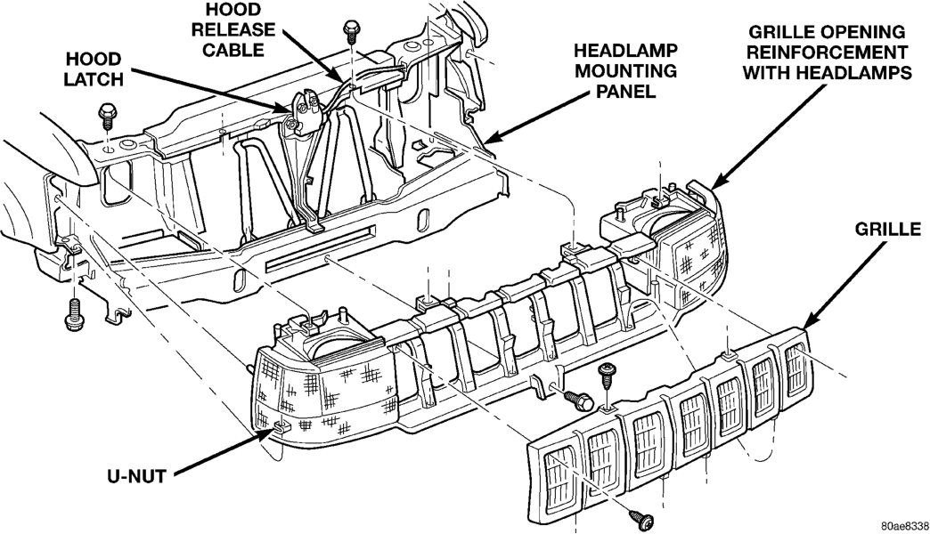
(1) Open hood. (2) Remove screws attaching grille to grille opening reinforcement (Fig. 1). (3) Separate grille from vehicle.
INSTALLATION
(1) Position grille at grille opening panel. (2) Install screws.
GRILLE OPENING REINFORCEMENT (GOR)
REMOVAL
(1) Open hood. (2) Remove grille. (3) Remove front fascia. Refer to Group 13, Frame and Bumpers for Removal/Installation procedures.
(4) If equipped, remove license plate bracket from bumper fascia/crossmember.
(5) Remove side marker and turn signal lamps. Refer to Group 8L, for Removal/Installation procedures.
(6) Remove headlamps.
(7) Remove bolts that attach grille opening reinforcement (GOR) to the upper and lower crossmember (Fig. 1).
(8) Remove grille opening reinforcement. (9) If necessary, remove air seals located at headlamp wiring inlets.
INSTALLATION
(1) If necessary, install air seals located at headlamp wiring inlets.
(2) Position grille opening reinforcement on vehicle.
(3) Install bolts that attach grille opening reinforcement (GOR) to the upper and lower crossmember (Fig. 1).
(4) Install headlamps. (5) Install side marker and turn signal lamps. Refer to Group 8L, for Removal/Installation procedures.
(6) If removed, install license plate bracket to bumper fascia/crossmember.
(7) Install front fascia. Refer to Group 13, Frame and Bumpers for Removal/Installation procedures.
(8) Install grille.
HOOD
REMOVAL
(1) Raise hood.
(2) If equipped, disconnect underhood lamp connector.
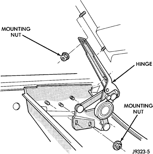
(3) Mark location of the hood hinges and hinge shims (Fig. 2) for installation alignment.
(4) Remove nuts that attach hinges to hood. Remove hood from vehicle with aid of a helper.
INSTALLATION
(1) Position hood on shims and hinges. Fingertighten hinge nuts.
(2) Align hinges and shims with installation reference marks. Tighten hinge nuts to 23 N·m (17 ft-lbs) torque.
(3) Test latch release cable and latches for proper operation.
(4) Connect underhood lamp connector. (5) Inspect hood for proper alignment and adjust as necessary.
HOOD INSULATION PANEL
REMOVAL
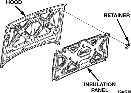
(1) Raise hood. (2) Remove the insulation panel fasteners (Fig. 3). (3) Remove the insulation panel from the hood.
INSTALLATION
(1) Position the insulation panel on the hood. (2) Install the insulation panel fasteners. (3) Close hood.
HOOD LOUVER
REMOVAL
(1) Raise hood. (2) Remove the nuts attaching the louver to the hood.
(3) Separate the louver from the hood.
INSTALLATION
(1) Position the louver on the hood. (2) Install the nuts attaching the louver to the hood.
(3) Close hood.
HOOD HINGE
(1) Remove hood from vehicle. (2) Remove hinge retaining nuts from studs (Fig. 2).
(3) Remove hinge from inner cowl side panel.
INSTALLATION
(1) Position hinge over studs. (2) Install hinge retaining nuts on studs. Tighten retaining nuts to 23 N·m (17 ft. lbs.) torque.
(3) Install hood. (4) Adjust hood as necessary. If necessary, refer to adjustment procedure.
HOOD LATCH
REMOVAL
(1) Remove nuts that attach latch to radiator crossmember support (Fig. 4).
(2) Disconnect latch from the hood release cable. Remove latch.
INSTALLATION
(1) Connect latch to latch release cable. Position it on radiator crossmember support.
(2) Install nuts. Tighten nuts to 11 N·m (8 ft-lbs) torque.
(3) Test operation of latch release cable and latch.
HOOD LATCH STRIKER
REMOVAL
(1) Remove bolts attaching striker to hood. (2) Remove striker from hood.
INSTALLATION
(1) Position striker on hood. (2) Install bolts. Tighten bolts to 11 N·m (8 ft-lbs) torque.
(3) Test striker/hood alignment by opening and closing hood several times. Adjust striker, if necessary.
HOOD RELEASE CABLE
REMOVAL
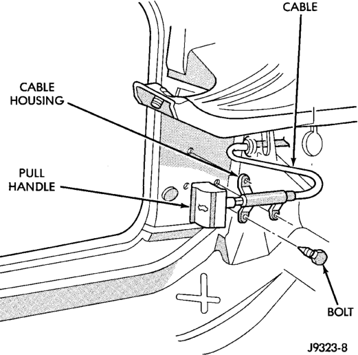
(1) Disconnect cable from hood latch. (2) Disconnect cable from retaining clips. (3) Remove left cowl side (kick) trim panel. (4) Remove cable bracket attaching screws from cowl side panel (Fig. 5).
(5) Pull cable through dash panel and remove it from under instrument panel.
INSTALLATION
(1) Insert replacement cable end through hole in dash panel into engine compartment.
(2) Pull cable forward and seat grommet in dash panel.
(3) Position cable bracket on cowl side panel and install screws. Tighten screws to 11 N·m (8 ft-lbs) torque.
(4) Install left cowl side trim panel. (5) Route cable into retaining clips. (6) Attach cable to hood latch. (7) Test release cable for proper operation.
SAFETY LATCH STRIKER
REMOVAL
(1) Remove latch striker screw from hood. (2) Remove striker from hood.
INSTALLATION
(1) Position striker on hood. Install screw. (2) Test safety latch operation.
COWL GRILLE AND SCREEN
REMOVAL
(1) Remove wiper arms. Refer to Group 8K, Wiper and Washer Systems for Removal/Installation procedures.
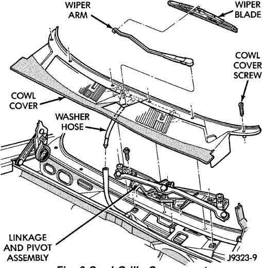
(2) Remove screws that attach grille to cowl (Fig. 6).
(3) Remove windshield washer tubes at connector. (4) Remove cowl grille and screen from cowl.
INSTALLATION
(1) Position cowl grille on cowl. Install windshield washer tubes at connector.
(2) Install cowl grille retaining screws. (3) Install windshield wiper arms.
EXTERIOR NAMEPLATES
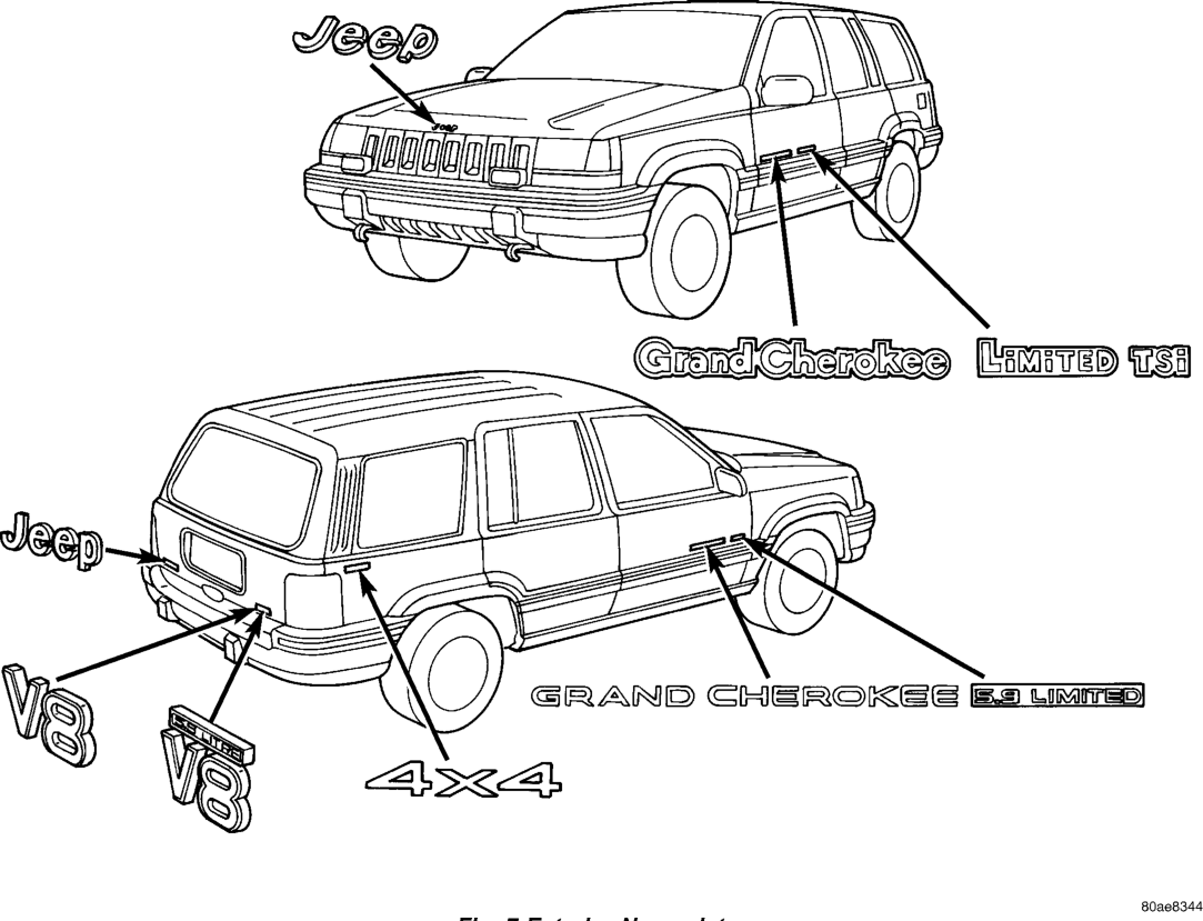
All of the vehicle exterior nameplates (Fig. 7), are attached to the vehicle panels with adhesive.
REMOVAL
(1) Using a trim stick or suitable tool, carefully pry nameplate from body panel.
INSTALLATION
(1) Clean panel surface. (2) Position replacement nameplate on panel and push inward to seat it.
BODY STRIPES/DECALS
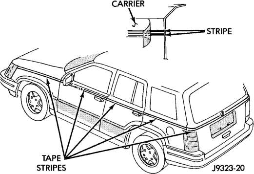
Body stripes are durable, weather-resistant tape stripes with pressure-sensitive backing. The tape stripe is protected by a carrier until installed on a body panel. Carrier also is an installation alignment aid.
REMOVAL
(1) Remove exterior trim as necessary to clear captured edges of tape stripe being removed
(2) Remove tape stripe using a suitable heat gun or lamp. This will soften adhesive backing.
(3) Clean adhesive residue from body finish using a suitable adhesive remover.
INSTALLATION
The painted surface of the body panel to be covered by a tape stripe must be smooth and completely cured before stripe can be applied. If painted surface is not smooth, wet sand with 600 grit wet/dry sand paper until surface is smooth.
Ripples and feather edges will read through stripe if surface is not properly prepared. Installation Equipment: • Bucket filled with a mild dish soap solution. • Lint free applicator cloth or sponge. • Body putty applicator squeegee. • Heat gun or sun lamp. • Razor knife. (1) With backing still in place, position stripe across panel to receive the stripe. Apply masking at top of stripe to hold it in position.
(2) Mark outside edge of panel on stripe with grease pencil.
(3) Trim stripe to within 17 mm (0.750 in.) of outline marks.
(4) Spread stripe across a smooth flat work surface, stripe side down.
(5) Peel paper backing away from stripe exposing adhesive backing of stripe (Fig. 8).
(6) Apply soap solution liberally to adhesive backing of stripe. (7) Apply soap solution to body panel surface. (8) Place stripe into position on body panel. Smooth out wrinkles by pulling lightly on edges of tape stripe until it lays flat on panel surface.
(9) Push air pockets from under tape stripe to perimeter of panel from center of the tape stripe out.
(10) Remove air bubbles from under tape stripe using a body putty squeegee.
CAUTION: Do nut cut into painted surface of body when trimming tape stripe to size.
(11) Trim tape stripe to size using a razor knife. Leave at least 13 mm (0.5 in.) for edges of doors and openings.
CAUTION: Do not overheat tape stripe when performing step 12.
(12) Apply heat to tape stripe to evaporate residual moisture from edges of tape stripe. This will also allow tape stripe to be stretched into concave surfaces.
(13) Edge turn tape stripe around doors or fenders. (14) Install exterior trim if necessary. Small air or water bubbles under tape stripe can be pierced with a pin and smoothed out.
SIDE VIEW MIRRORS
REMOVAL
(1) Remove door trim panel. (2) Disengage power mirror connector from trim panel.
(3) If equipped, disengage two-way electrochromic mirror connector from wiring harness.
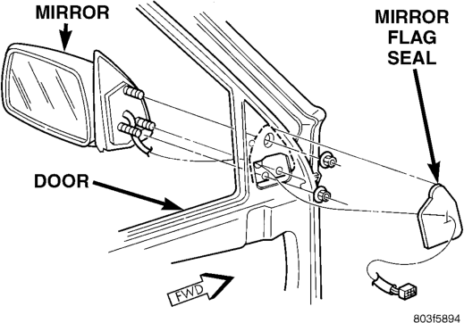
(4) Remove clips attaching mirror harness to door inner panel. (5) Remove mirror flag seal. (6) Remove mirror retaining nuts (Fig. 9). (7) Remove mirror from door. Refer to Group 8, Electrical for additional information involving power mirrors.
INSTALLATION
(1) Position mirror on door. Verify that the gasket seal is properly positioned.
(2) Install mirror retaining nuts. (3) Install mirror flag seal. (4) Install clips attaching mirror harness to door inner panel. (5) If equipped, engage two-way electrochromic mirror connector to wiring harness.
(6) Engage power mirror connector at trim panel. (7) Install door trim panel.
FRONT FENDER
REMOVAL
(1) Remove headlamp, side marker and turn signal lamp. Refer to Group 8L, Lamps for service information.
(2) Remove front bumper fascia. Refer to Group 13, Frame and Bumpers for service information.
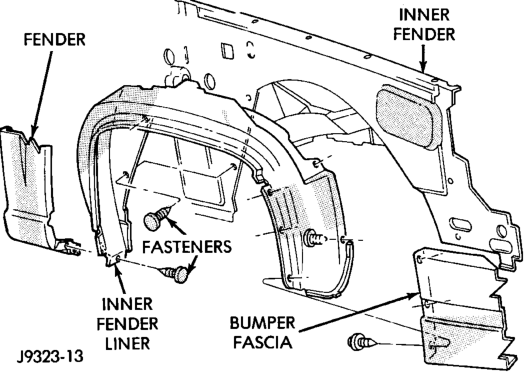
(3) Remove front wheel. (4) Remove fasteners attaching inner front fender liner to fender and inner fender (Fig. 10).
(5) Remove inner fender liner. (6) Right fender only:
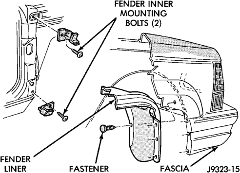
(a) If equipped, remove radio antenna mast, nut, pad and base from fender. Refer to group 8F, Audio Systems for Removal/Installation procedures. (7) From inside wheel well, remove bolts at rear of fender reinforcements (Fig. 11).
(8) Remove bolts at front fender bracket (Fig. 12). (9) Remove bolts at lower rear of fender at A-pillar. (10) Remove upper mounting bolts at top of fender. (11) Remove fender from inner fender.
INSTALLATION
(1) Position fender on inner fender panel. (2) Install all of fender attaching screws fingertight.
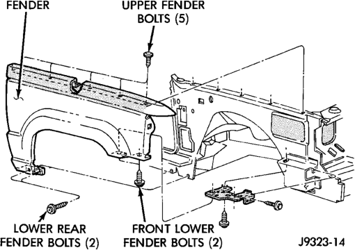
(3) Align fender with adjacent body panels. Tighten fender bolts to 9 N·m (80 in-lbs) torque.
(4) Install inner fender liner. (5) Install front wheel. (6) Install front bumper fascia. If necessary refer to Group 13, Frame and Bumpers for installation instructions. (7) Install front headlamp, side marker and turn signal lamp. If necessary refer to Group 8L, Lamps for service information.
FRONT DOOR TRIM PANEL
REMOVAL
(1) Remove screw attaching trim panel to inside release handle (Fig. 13).
(2) Remove screw at armrest. (3) Remove screw at the upper mirror bezel. (4) Remove the screw in the trim panel depression. (5) Using trim remover (C-4829 or equivalent), detach trim panel perimeter push-in fasteners from door inner panel.
(6) If equipped, disconnect the wiring connectors from power switch panel.
(7) Lift trim panel over inside release handle and remove trim panel from door.
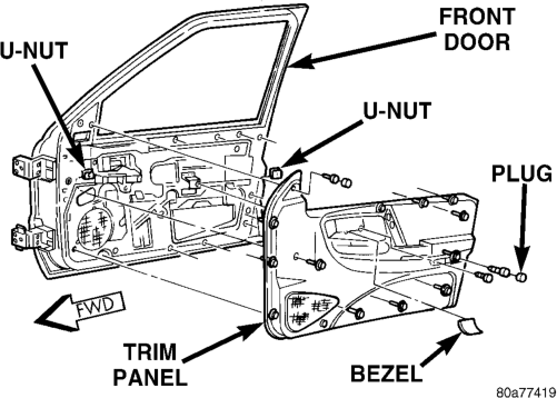
INSTALLATION
(1) If equipped, connect the wiring connectors to power switch panel.
(2) Position trim panel on door inner panel. (3) Press push-in fasteners inward around perimeter of door to attach it to inner panel.
(4) Install armrest screw. (5) Install mirror bezel screw. (6) Install the screw in the trim panel depression. (7) Install screw attaching trim panel to inside release handle.
FRONT DOOR WATERDAM
REMOVAL
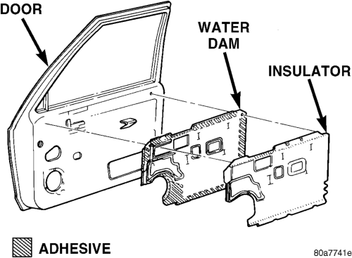
(1) Remove the door trim panel. (2) Peel the insulator and waterdam from the door. (3) Route all harnesses through waterdam as necessary.
(4) Separate insulator and waterdam from door (Fig. 14).
INSTALLATION
(1) Waterdam contact surface must be free of contaminants. Clean as necessary.
(2) Route all harnesses through waterdam as necessary.
(3) Position waterdam and insulator on door and align all holes.
(4) Press waterdam and insulator on door. (5) Install the door trim panel.
FRONT DOOR
REMOVAL
(1) Remove trim panel. (2) If equipped, disconnect power window regulator, power door lock motor and all other wire harness connectors.
(3) Slide wire harness out of boot and door (4) Mark an outline around door hinges for installation alignment reference.
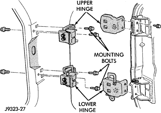
(5) Remove door hinge, retaining bolts, plates and shims (Fig. 15).
(6) Identify and retain door hinge plates and shims for correct installation.
(7) Separate door from vehicle.
INSTALLATION
(1) If a replacement front door is being installed, coat door interior with anti-corrosion wax. Also, seal door hem flange with sealant.
(2) Transfer original hardware. If necessary, refer to applicable procedures.
(3) Position door in body opening. (4) Align door hinges, plates and shims with bolt holes. Install (but do not tighten) hinge bolts.
(5) Adjust door to reference marks. If necessary, refer to adjustment procedure. Tighten hinge bolts to 35 N·m (26 ft-lbs) torque.
(6) Adjust latch striker as necessary. (7) If applicable, route and connect harness connectors to door and vehicle body wire harness connectors.
(8) Install door waterdam (if removed), trim panel.
FRONT DOOR HINGE
REMOVAL
(1) Open and support door. (2) Remove bolts attaching hinge to B-pillar (Fig. 16).
(3) Separate door from vehicle.
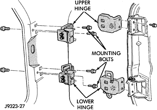
INSTALLATION
(1) Support door. (2) Position door at B-pillar. (3) Install bolts attaching hinge to B-pillar. Tighten outer bolts to 40 N·m (360 in. lbs.) and inner bolts 34 N·m (300 in. lbs.) torque.
FRONT DOOR OUTSIDE HANDLE
REMOVAL
(1) Remove door trim panel and waterdam. (2) Remove access hole cover and door handle retaining nuts.
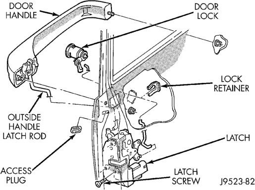
(3) Disconnect handle latch rod from latch (Fig. 17).
INSTALLATION
(1) Reverse removal procedure.
FRONT DOOR LOCK CYLINDER
REMOVAL
(1) Remove door trim panel and waterdam. If necessary. refer to removal procedure.
(2) Disconnect door latch lock cylinder rod at door latch (Fig. 17).
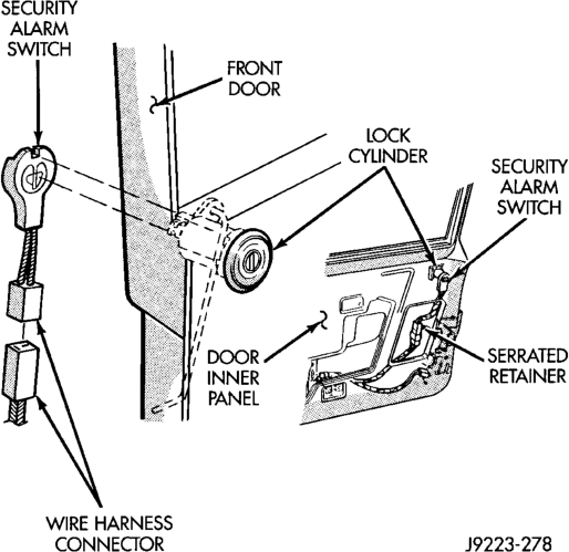
(3) If equipped, disconnect security alarm switch connector from lock cylinder (Fig. 18).
(4) Remove key lock cylinder retainer clip. Remove lock cylinder, gasket and clip from door.
(5) If applicable, remove door latch lock cylinder rod from original lock cylinder. Connect it to replacement lock cylinder.
INSTALLATION
(1) Reverse removal procedure.
FRONT DOOR LATCH
REMOVAL
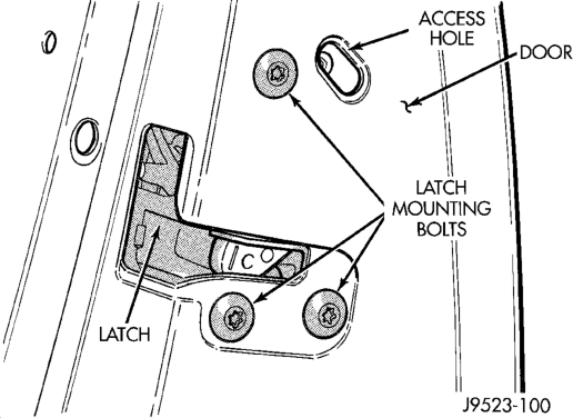
(1) Remove door trim panel and waterdam. (2) Remove door latch retaining screws (Fig. 19). (3) Disconnect all rods from door latch (Fig. 20). (4) Disconnect wire connector, if equipped. (5) Remove door latch from door.
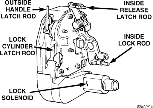
INSTALLATION
(1) Reverse removal procedure. Tighten latch screws to 10 N·m (95 in. lbs.) torque.
FRONT DOOR LATCH STRIKER
REMOVAL
(1) Remove screws attaching striker to B-pillar. (2) Separate striker from B-pillar.
INSTALLATION
(1) Position striker on B-pillar. (2) Install screws attaching striker to B-pillar. Tighten screws to 5 N·m (45 in. lbs.) torque.
FRONT DOOR INSIDE HANDLE ACTUATOR
REMOVAL
(1) Remove door trim panel and waterdam. If necessary, refer to removal procedure.
(2) Remove door inside latch release handle screws (Fig. 21).
(3) Move door release handle outward. Disconnect handle latch and lock rods.
(4) Remove door inside handle actuator from door.
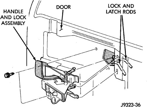
INSTALLATION
(1) Reverse removal procedure.
FRONT DOOR INNER BELT SEAL
REMOVAL
(1) Remove door trim panel. (2) Using a trim stick, carefully pry rear inner edge of seal upward.
(3) Grasp seal and pull upward to separate from door flange (Fig. 22).
INSTALLATION
(1) Position seal on door flange. (2) Firmly press downward to seat seal on flange. (3) Install trim panel.
FRONT DOOR OUTER BELT SEAL
REMOVAL
(1) Lower window glass. (2) Remove screw from inner door panel attaching seal to outer door panel (Fig. 23).
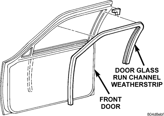
(3) Grasp seal and pull rearward to release it from side view mirror bezel.
(4) Lift seal upward and separate from door.
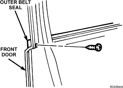
INSTALLATION
(1) Lightly lubricate the front of the seal (2) Position the seal onto the door flange. (3) Slide the front of the seal behind the side view mirror bezel. Force the seal onto door flange. Continue rearward until it is seated on flange.
(4) Install the screw securing the seal to the outer door panel.
FRONT DOOR RUN CHANNEL WEATHERSTRIP
REMOVAL
(1) Lower window glass. (2) Grasp seal from upper run channel corner and firmly separate weatherstrip from flange (Fig. 24).
INSTALLATION
NOTE: Soapy water may be used to aid in installation.
(1) Position weatherstrip on flange aligning notches in each corner.
(2) Press weatherstrip into position.
FRONT DOOR OPENING WEATHERSTRIP
REMOVAL
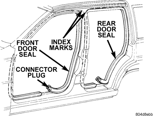
(1) Remove A-pillar trim panel. (2) Remove B-pillar upper trim panel. (3) Remove B-pillar lower trim panel. (4) Grasp seal and separate from door opening.
INSTALLATION
(1) Position weatherstrip at corners using paint dots as alignment points.
(2) Move upward and around edge of door opening. Seat seal on flange (Fig. 25).
(3) Engage connector plug with each end of weatherstrip at bottom of door opening.
(4) Install B-pillar lower trim panel. (5) Install B-pillar upper trim panel. (6) Install A-pillar trim panel.
FRONT DOOR WINDOW REGULATOR
REMOVAL
(1) Remove door trim panel and waterdam. If necessary, refer to removal procedure.
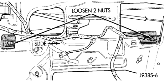
(2) Position window glass to access window track nuts (Fig. 26).
(3) Loosen window track nuts and slide track off of the window.
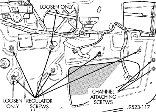
(4) Remove window regulator retaining screws (Fig. 27).
(5) Lift window upward and separate it from regulator. Support window.
(6) Remove window regulator from door.
INSTALLATION
(1) Reverse removal procedure.
FRONT DOOR WINDOW GLASS
REMOVAL
(1) Remove door trim panel and waterdam. If necessary, refer to removal procedure.
(2) Remove beltline molding and weatherstrip seals.
(3) Remove window track retaining nuts. (4) Lift window glass upward and out of door.
INSTALLATION
(1) Lower window glass into position. (2) Install window track retaining nuts. (3) Install beltline molding and weatherstrip seals. (4) Install door trim panel and waterdam.
REAR DOOR TRIM PANEL
REMOVAL
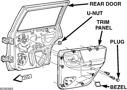
(1) Remove screw attaching trim panel to inside release handle (Fig. 28).
(2) Remove screw at armrest. (3) Using trim remover (C-4829 or equivalent), detach trim panel perimeter push-in fasteners from door inner panel.
(4) If equipped, disconnect the wiring connectors from power switch panel.
(5) Lift trim panel over inside release handle and remove trim panel from door.
INSTALLATION
(1) If equipped, connect the wiring connectors to power switch panel.
(2) Position trim panel on door inner panel. (3) Press push-in fasteners inward around perimeter of door to attach it to inner panel.
(4) Install armrest screw. (5) Install mirror bezel screw. (6) Install screw attaching trim panel to inside release handle.
REAR DOOR
REMOVAL
(1) Remove door trim panel. (2) Disconnect power window regulator, power door lock motor and all other wire harness connectors.
(3) Slide wire harness out of boot and door. (4) Mark an outline around door hinges for installation alignment reference.
(5) Remove door hinge, retaining bolts, plates and shims (Fig. 29). Remove door from vehicle.
(6) Identify and retain door hinge plates and shims for correct installation.
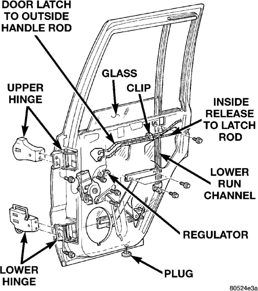
INSTALLATION
(1) If a replacement front door is being installed, coat door interior with anti-corrosion wax. Also, seal door hem flange with sealant.
(2) Before installing a replacement door, transfer original hardware. If necessary, refer to applicable procedures.
(3) Position door in body opening. (4) Align door hinges, plates and shims with bolt holes. Install (but do not tighten) hinge bolts.
(5) Adjust door to reference marks. If necessary, refer to adjustment procedure. Tighten hinge bolts to 28 N·m (250 in. lbs.) torque.
(6) Adjust latch striker as necessary. (7) If applicable, route and connect harness connectors to door and vehicle body wire harness connectors.
(8) Install door waterdam (if removed), trim panel, armrest and window glass regulator handle.
REAR DOOR HINGE
REMOVAL
(1) Open and support door. (2) Remove bolts attaching hinge to C-pillar (Fig. 30).
(3) Separate door from vehicle.
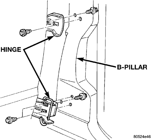
INSTALLATION
(1) Support door. (2) Position door at C-pillar. (3) Install bolts attaching hinge to C-pillar. Tighten outer bolts to 40 N·m (360 in. lbs.) and inner bolts 34 N·m (300 in. lbs.) torque.
REAR DOOR OUTSIDE HANDLE
REMOVAL
(1) Remove door trim panel and waterdam. If necessary, refer to removal/installation procedure.
(2) Remove access hole cover and door handle retaining nuts (Fig. 31).
(3) Disconnect handle latch rod from latch.
INSTALLATION
(1) Reverse removal procedure.
REAR DOOR LATCH
REMOVAL
(1) Remove door trim panel and waterdam. If necessary, refer to removal procedure.
(2) Remove door latch retaining screws (Fig. 31). (3) Disconnect all rods from door latch.
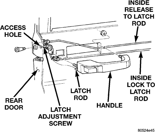
(4) Remove door latch from door.
INSTALLATION
(1) Reverse removal procedure.
REAR DOOR LATCH STRIKER
REMOVAL
(1) Open door. (2) Remove screws attaching striker to C-pillar (Fig. 32).
(3) Separate striker and spacer from vehicle.
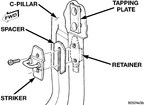
INSTALLATION
(1) Position striker and spacer on C-pillar. (2) Install screws. Tighten to 28 N·m (250 in. lbs.) torque.
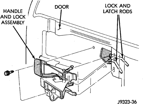
REAR DOOR INSIDE HANDLE ACTUATOR
REMOVAL
(1) Remove door trim panel and waterdam. (2) Remove door inside handle actuator screws (Fig. 33).
(3) Move actuator handle outward. Disconnect handle latch and lock rods.
(4) Remove door inside release handle from door.
INSTALLATION
Reverse removal procedure.
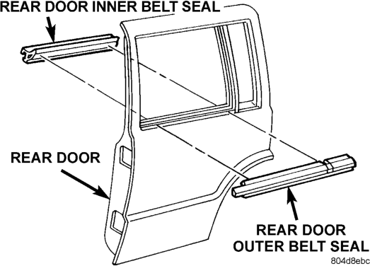
REAR DOOR INNER BELT SEAL
REMOVAL
(1) Remove door trim panel. (2) Using a trim stick, carefully pry rear inner edge of seal upward.
(3) Grasp seal and pull upward to separate from door flange (Fig. 34).
INSTALLATION
(1) Position seal on door flange. (2) Firmly press downward to seat seal on flange. (3) Install trim panel.
REAR DOOR OUTER BELT SEAL
REMOVAL
(1) Lower window glass. (2) Remove screw from inner door panel attaching seal to outer door panel (Fig. 35).
(3) Lift seal upward and separate from door.

INSTALLATION
(1) Position the seal onto the door flange. (2) Tuck outer belt sealing lips inside glass run channel and around division bar.
(3) Force the seal onto door flange. Continue rearward until it is seated on flange.
(4) Install the screw securing the seal to the outer door panel.
REAR DOOR OPENING WEATHERSTRIP
REMOVAL
(1) Remove C-pillar trim panel. (2) Remove B-pillar upper trim panel. (3) Remove B-pillar lower trim panel. (4) Remove screws at the front of the quarter trim panel.
(5) Grasp seal and separate from door opening.
INSTALLATION
(1) Position weatherstrip at corners using paint dots as alignment points.
(2) Move upward and around edge of door opening. Seat seal on flange (Fig. 25).
(3) Engage connector plug with each end of weatherstrip at bottom of door opening.
(4) Install screws at the front of the quarter trim panel.
(5) Install B-pillar lower trim panel. (6) Install B-pillar upper trim panel. (7) Install C-pillar trim panel.
REAR DOOR WINDOW REGULATOR
REMOVAL
(1) Remove door trim panel and waterdam. If necessary, refer to removal procedure.
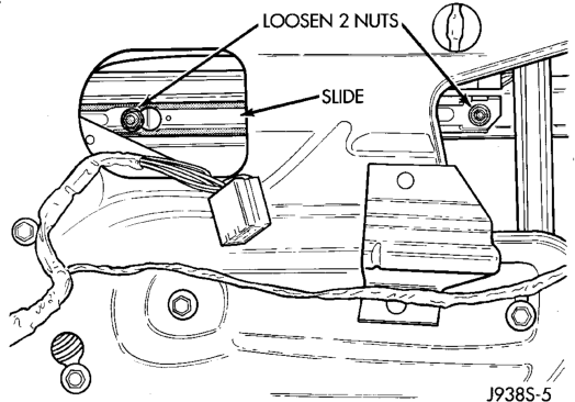
(2) Position window glass to access window track nuts (Fig. 36).
(3) Loosen window track nuts and slide track off of window.
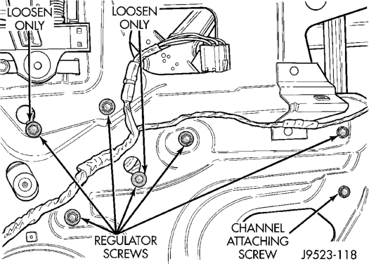
(4) Remove window regulator retaining screws (Fig. 37).
(5) Lift window upward and separate it from regulator. Support window.
(6) Remove window regulator from door.
INSTALLATION
(1) Reverse removal procedure.
REAR DOOR WINDOW GLASS
REMOVAL
(1) Lower window glass. (2) Remove trim panel and waterdam from door inner panel. If necessary, refer to removal procedure. (3) Pry window beltline molding from flange. Remove molding from door.
(4) Remove window weatherstrip seals from door. (5) Remove window track nuts and slide track off of window.
(6) Remove division bar upper attaching screw and belt line screw (Fig. 38).
(7) Tilt stationary glass channel assembly forward and remove it from door.
(8) Remove window glass from door.
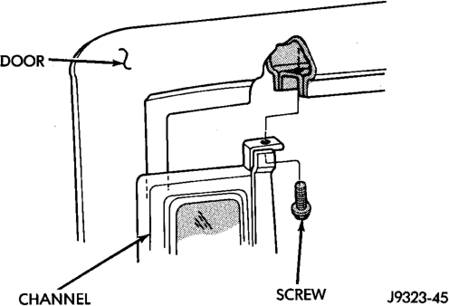
INSTALLATION
(1) Install window glass in door. (2) Tighten glass track nuts to 6 N·m (53 in-lbs) torque.
(3) Install stationary glass channel in door. (4) Install stationary glass channel screws. Tighten screw to 6 N·m (5 ft-lbs) torque.
(5) Install window glass channel and belt weatherstrip seals.
(6) Install window beltline molding. (7) Install door waterdam and trim panel. If necessary, refer to installation procedure.
FUEL DOOR
REMOVAL
(1) Open fuel door. (2) Remove rear quarter trim panel. (3) Remove screw attaching fuel door to body panel (Fig. 39).
(4) Separate fuel door from vehicle.
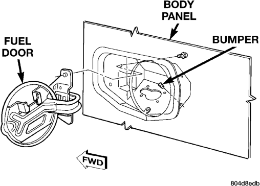
INSTALLATION
(1) Position fuel door at vehicle. (2) Install screw attaching fuel door to body panel. (3) Install rear quarter trim panel. (4) Close fuel door.
BODY SIDE CLADDING
REMOVAL—FRONT DOOR
(1) Using a trim stick, gently lift up from bottom of cladding. Unsnap molding from retaining clips (Fig. 40).
(2) Lift upward and remove molding.
INSTALLATION—FRONT DOOR
(1) Replace all retaining clips. (2) Install molding over top of retaining clips. (3) Align molding to door edges. (4) Snap molding down over retaining clips.
REMOVAL—REAR DOOR
(1) Open rear door. (2) Remove acorn nut at rear dogleg (Fig. 40). (3) Using a trim stick, gently lift up from bottom of cladding. Unsnap molding from retaining clips.
INSTALLATION—REAR DOOR
(1) Replace all retaining clips. (2) Install molding retainer into hole at dogleg. (3) Install molding over top of retaining clips. (4) Snap molding down over top of retaining clips. (5) Install acorn nut onto retainer.
REMOVAL—FENDER/QUARTER PANEL
(1) Remove screws at wheel opening. (2) Using a trim stick, Gently pry upward from bottom of cladding.
(3) Unsnap cladding from retainers.
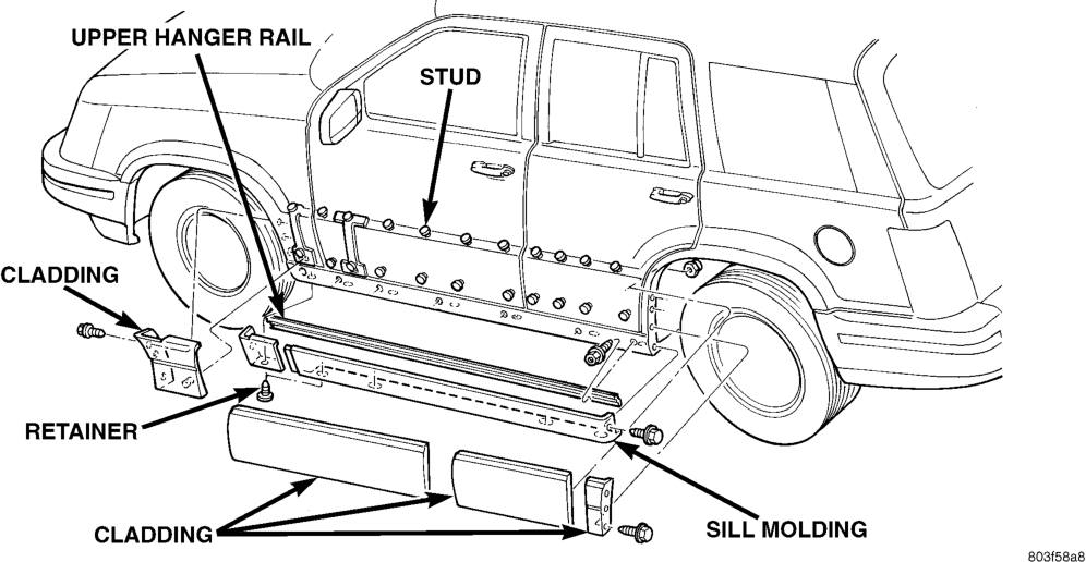
INSTALLATION—FENDER/QUARTER PANEL
(1) Replace all retaining clips. (2) Install molding over top of retainer clips. (3) Snap molding down over retaining clips. (4) Install screws into wheel opening.
A-PILLAR TRIM
REMOVAL
(1) Using a trim stick, carefully pry A-pillar trim from A-pillar (Fig. 41).
INSTALLATION
(1) Position A-pillar trim panel at A-pillar and snap into place.
(2) Ensure that the A-pillar covers the inner edge of the door opening weatherstrip.
ASSIST HANDLE
REMOVAL
(1) Remove the screws attaching the handle to the headliner (Fig. 42).
(2) Remove assist handle from roof panel.
INSTALLATION
(1) Position handle on the roof panel. (2) Install the screws. Tighten screws to 3 N·m (22 in-lbs) torque.
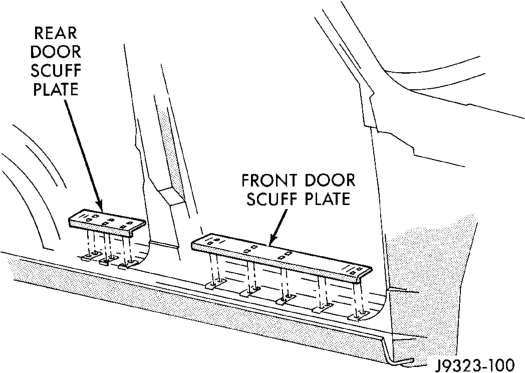
FRONT DOOR SCUFF PLATE
REMOVAL
The front door scuff plate is attached with molded-in snap retainers.
(1) Using a trim stick or similar tool, carefully pry scuff plate from sill. Detach scuff plate from sill (Fig. 43).
INSTALLATION
(1) Position scuff plate on sill and snap into place.
UPPER B-PILLAR TRIM PANEL
REMOVAL
(1) Remove the A-pillar trim panel. (2) Remove front seat belt turning loop. (3) Detach and remove upper B-pillar trim panel.
INSTALLATION
(1) Position trim panel on B-pillar. (2) Ensure the trip panel covers the inner edge of the door opening weatherstrip.
(3) Install front seat belt turning loop. (4) Install the A-pillar trim panel.
LOWER B-PILLAR TRIM PANEL
REMOVAL
(1) Remove the A-pillar trim panel. (2) Remove upper B-pillar trim panel. (3) Remove screws attaching lower B-pillar trim panel to B-pillar (Fig. 44).
(4) Remove screws attaching cowl trim panel.
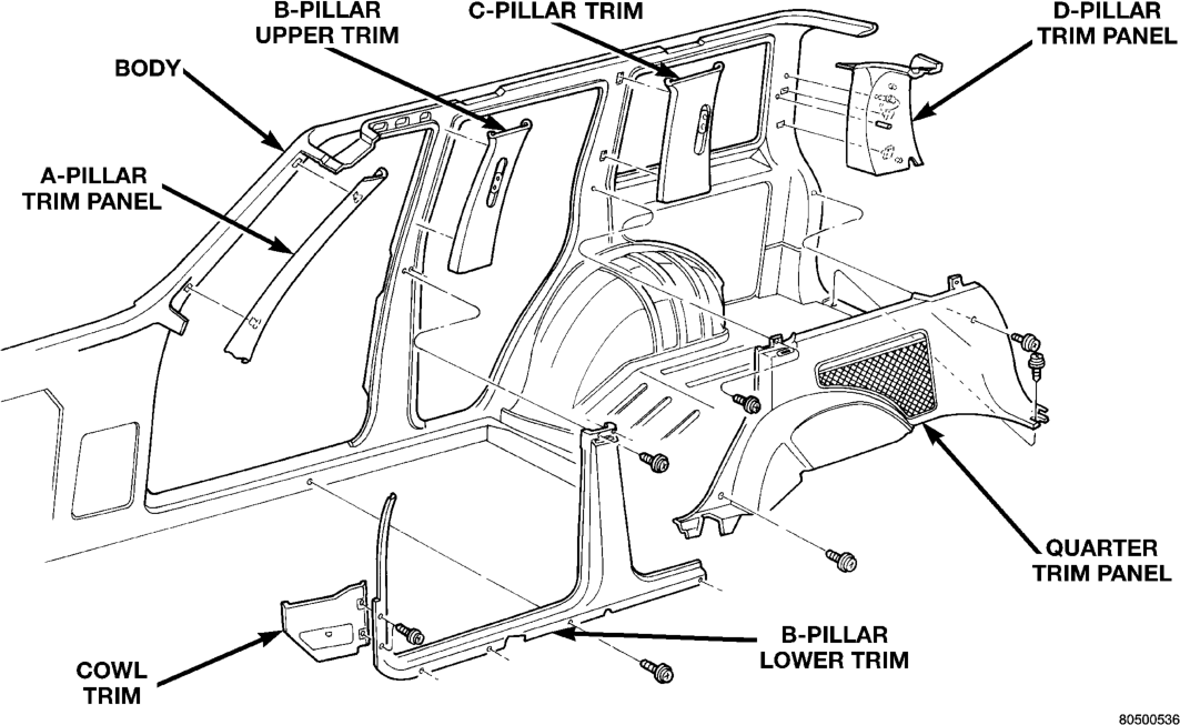
(5) Separate lower B-pillar trim panel from B-pillar.
(6) Route seat/shoulder belt through access slot in lower B-pillar trim panel.
(7) Remove lower B-pillar trim panel (Fig. 41).
INSTALLATION
(1) Position lower B-pillar trim panel on vehicle. (2) Route seat/shoulder belt through access slot in lower B-pillar trim panel.
(3) Install screws that attach lower B-pillar trim panel to B-pillar.
(4) Install screws attaching cowl trim panel. (5) Slide upper B-pillar trim panel downward into place.
(6) Install the A-pillar trim panel.
REAR DOOR SCUFF PLATE
REMOVAL
The rear door scuff plate is attached with molded-in snap retainers.
(1) Using a trim stick or similar tool, carefully pry scuff plate from sill. Detach scuff plate from sill (Fig. 43).
INSTALLATION
(1) Position scuff plate on sill and snap into place.
C-PILLAR TRIM
REMOVAL
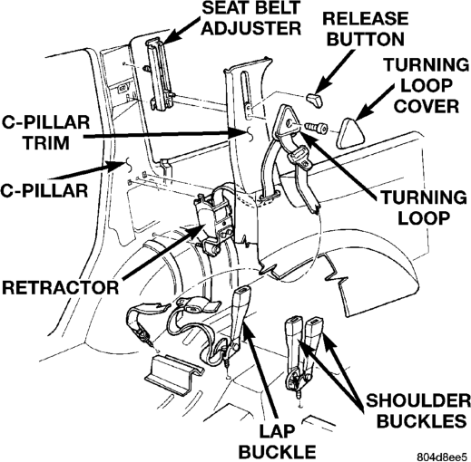
(1) Remove rear seat belt turning loop. (2) Using a trim stick, carefully pry C-pillar trim panel from vehicle (Fig. 41).
INSTALLATION
(1) Position C-pillar trim panel on C-pillar. Ensure the adjustable turning loop is aligned with the trim panel slider and snap into place.
(2) Install rear seat belt turning loop.
QUARTER TRIM PANELS
(1) Pull rear seat bottom forward and fold down rear seat.
(2) Remove lower retaining screw at rear door opening (Fig. 41).
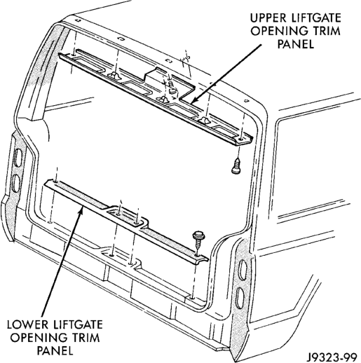
(3) If equipped, remove sunshade cover. (4) Remove C-pillar trim panel. (5) Remove screws retaining upper liftgate opening trim panel.
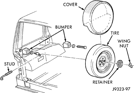
(6) Disconnect wiring to cargo lamp. (7) Remove lower liftgate opening trim panel. (8) Remove D-pillar upper trim panel. (9) Remove quarter trim panel mounting screws. (10) If necessary, remove spare tire and tire standoffs from left quarter trim panel (Fig. 45).
(11) Remove rear quarter trim panel.
INSTALLATION
(1) Reverse removal procedure.
D-PILLAR TRIM
REMOVAL
(1) Remove liftgate opening upper trim panel (Fig. 46).
(2) Detach and remove trim panel from D-pillar (Fig. 41).
INSTALLATION
(1) Position D-pillar trim panel on D-pillar and snap in place.
(2) Install upper liftgate opening trim panel.
FRONT SHOULDER BELT/BUCKLE
REMOVAL—BUCKLE
(1) Slide front seats all the way forward for access to buckle anchor bolt.
(2) Remove anchor bolt cover. (3) Remove buckle anchor bolt. (4) Remove shoulder belt buckle from transmission tunnel.

(1) Position seat belt buckle in position and anchor bolt.
(2) Install anchor bolt cover.
REMOVAL—SHOULDER BELT
(1) Unsnap turning loop cover. (2) Remove upper anchor bolt (Fig. 47). (3) Remove B-pillar trim panels. (4) Remove bolt attaching retractor to B-pillar. (5) Remove bolt attaching belt anchor to B-pillar. (6) Disconnect retractor wire harness connector. (7) Remove shoulder belt and retractor.
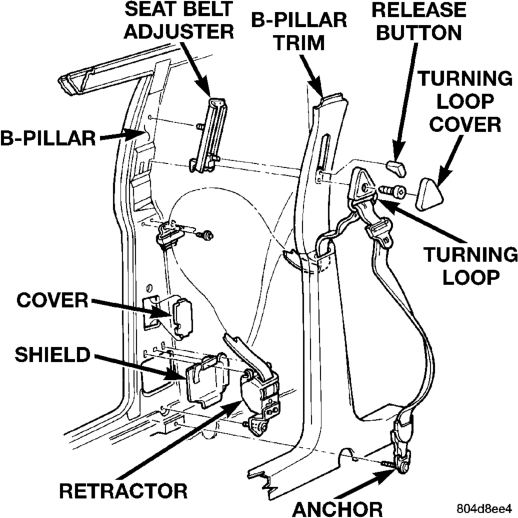

(1) Reverse removal procedure. Tighten anchor bolts to 37 N·m (27 ft-lbs)
REAR SHOULDER/LAP BELT/BUCKLE
REMOVAL—LAP BELT/BUCKLE
(1) Pull rear seat release loop and tilt seat bottom forward. Remove seat bottom from lower latch.
(2) Unlatch seat back and tilt forward.
(3)
Remove shoulder belt buckle and lap belt/buckle anchor plate bolts from the floor panel (Fig. 48).
INSTALLATION—LAP BELT/BUCKLE
(1) Position shoulder belt buckle and lap belt/ buckle on the floor panel.
(2) Install bolts attaching lap belt/buckle to floor panel. Tighten anchor bolts to 37 N·m (27 ft-lbs).
REMOVAL—SHOULDER BELT
(1) Unsnap turning loop cover. (2) Remove turning loop anchor bolt (Fig. 48). (3) Remove C-pillar and quarter trim panel. (4) Remove belt retractor anchor bolt from rear quarter rail.
(5) Remove retractor and shoulder belt from panel.

(1) Position retractor and shoulder belt on panel. (2) Install belt retractor anchor bolt in rear quarter rail. Tighten anchor bolts to 37 N·m (27 ft-lbs).
(3) Install C-pillar and quarter trim panel. (4) Install turning loop anchor bolt. Tighten anchor bolt to 37 N·m (27 ft-lbs).
(5) Install turning loop cover.
FRONT BUCKET SEAT
REMOVAL
Remove bolts attaching seat to floor pan (Fig. 49).
(1)
(2) If equipped, disconnect power seat wire harness connector.
(3) Remove seat from floor panel.
INSTALLATION
(1) Position seat on floor pan. (2) If equipped, connect power seat wire harness connector.
(3) Install bolts attaching seat to floor pan. Tighten front bolts to 27 N·m (20 ft. lbs.) torque, tighten rear bolts to 27 N·m (20 ft. lbs.) torque.
FLOOR CONSOLE
REMOVAL
(1) With the engine off, position the transmission shift lever in first gear.
(2) Grasp transmission shift lever handle and firmly pull straight up.
(3) Separate transmission shift lever handle from shift lever.
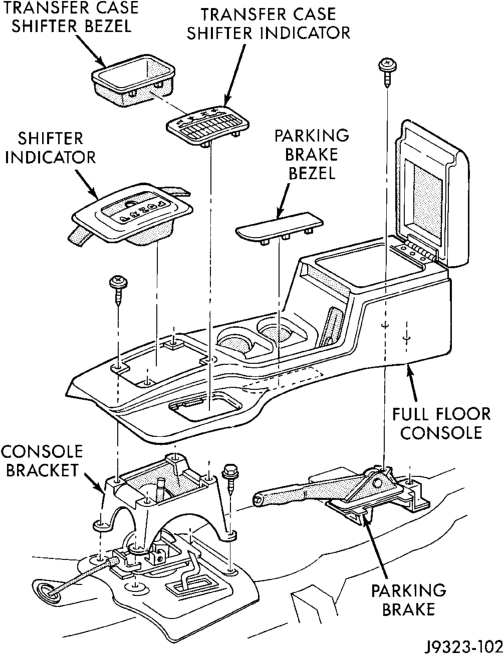
(4) Remove transmission and transfer case shift indicator bezels by prying upward to release them. Position flat screwdriver between bezel and console to remove indicator bezel.
(5) Disconnect lamp sockets from bezels. (6) Remove screws attaching console to the console bracket (Fig. 50).
(7) Remove console from floor.
INSTALLATION
(1) Position console in the vehicle. (2) Install screws attaching console to console bracket.
(3) Connect lamp sockets in bezels. (4) Install transmission and transfer case shift indicator bezels (Fig. 50). (5) Position transmission shift lever handle on shift lever and press firmly downward to lock into place.
REAR SEAT CUSHION
REMOVAL
(1) Disengage seat cushion at rear by pulling upward on release strap.
(2) Tilt cushion forward. (3) Disengage seat cushion by pulling upward and out.
(4) Remove seat cushion from vehicle.
INSTALLATION
(1) Position seat cushion in vehicle. (2) Insert hinge into lower pivot. (3) Push downward to engage hinge into pivot. (4) Rotate cushion downward into seating position. (5) Lock seat cushion down by pressing firmly on center of cushion until latch engages.
REAR SEATBACK
REMOVAL
(1) Remove lower seat cushion. Refer to removal procedure.
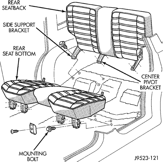
(2) Remove bolts holding seatback side support brackets (left side) (Fig. 51).
(3) Tilt seatback forward, and slide it outboard to detach it from pin on center pivot bracket.
(4) Remove left side (60%) seatback from vehicle.
(5) Remove bolts holding seatback side support brackets (right side) (Fig. 51).
(6) Remove right side (40%) seatback from vehicle.
INSTALLATION
(1) Position right side (40%) seatback in vehicle. (2) Position right side support brackets with bolt holes aligned and install support bracket bolts. Tighten bolts to 27 N·m (20 ft. lbs.) torque.
(3) Position left side (60%) seatback in vehicle. (4) Install seatback onto center pivot bracket pin. Ensure seat back is properly engaged on the center pivot pin.
(5) Position left side support brackets with bolt holes aligned and install support bracket bolts. Tighten bolts to 27 N·m (20 ft. lbs.) torque.
(6) Install lower seat cushion. Refer to installation procedure.
FRONT CARPET/MAT
REMOVAL
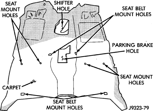
(1) Remove lower B-pillar trim panels. (2) Remove front and rear seats (as applicable). (3) As necessary, remove trim panels and moldings. (4) Remove floor console. (5) Remove all other interfering components. (6) Remove carpet and mat from floor panel (Fig. 52).
INSTALLATION
(1) Reverse removal procedure.
CARGO CARPET/MAT
REMOVAL
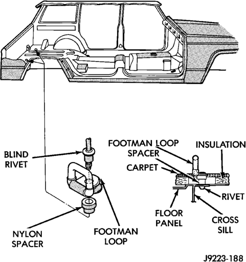
(1) Remove quarter trim panels. (2) Remove liftgate trim panel. (3) Drill-out retaining rivet heads and remove cargo tie-down footman loops from carpet (Fig. 53).
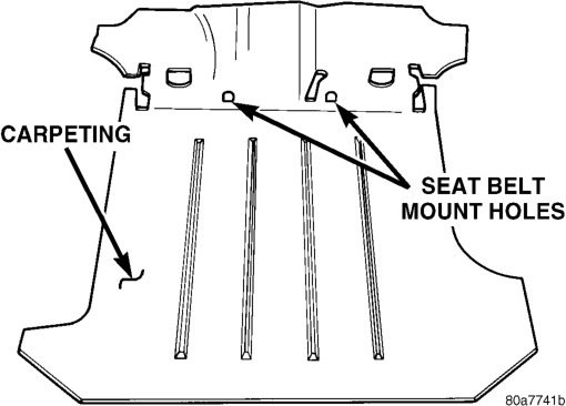
(4) Remove rear seats and belts. (5) Remove all other interfering components. (6) Remove carpet and mat from floor panel (Fig. 54).
(7) If necessary, remove skid strips from carpet.
INSTALLATION
(1) Reverse removal procedure.
REARVIEW MIRROR
REMOVAL
(1) If equipped, disconnect mirror harness wire connector.
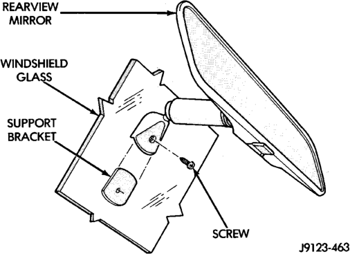
(2) Loosen the mirror base setscrew (Fig. 55). (3) Slide the mirror base upward and off the bracket.
INSTALLATION
(1) Position the mirror base at the bracket and slide it downward onto the support bracket.
(2) Tighten the setscrew 1 N·m (15 in. lbs.) torque. (3) If equipped, connect mirror harness wire connector.
REARVIEW MIRROR SUPPORT BRACKET
INSTALLATION
(1) Mark the position for the mirror bracket on the outside of the windshield glass with a wax pencil.
(2) Clean the bracket contact area on the glass. Use a mild powdered cleanser on a cloth saturated with isopropyl (rubbing) alcohol. Finally, clean the glass with a paper towel dampened with alcohol.
(3) Sand the surface on the support bracket with fine grit-sandpaper. Wipe the bracket surface clean with a paper towel.
(4) Apply accelerator to the surface on the bracket according to the following instructions:
• Crush the vial to saturate the felt applicator. • Remove the paper sleeve. • Apply accelerator to the contact surface on the bracket.
• Allow the accelerator to dry for five minutes. • Do not touch the bracket contact surface after the accelerator has been applied.
(5) Apply adhesive accelerator to the bracket contact surface on the windshield glass. Allow the accelerator to dry for one minute. Do not touch the glass contact surface after the accelerator has been applied.
(6) Install the bracket according to the following instructions: • Apply one drop of adhesive at the center of the bracket contact-surface on the windshield glass.
• Apply an even coat of adhesive to the contact surface on the bracket.
• Align the bracket with the marked position on the windshield glass.
• Press and hold the bracket in place for at least one minute.
NOTE: Verify that the mirror support bracket is correctly aligned, because the adhesive will cure rapidly.
(7) Allow the adhesive to cure for 8-10 minutes. Remove any excess adhesive with an alcohol-dampened cloth.
(8) Allow the adhesive to cure for an additional 8-10 minutes before installing the mirror.
SUNVISOR
REMOVAL
(1) Remove screws that attach sunvisor arm support bracket to headliner and roof panel (Fig. 56).
(2) Detach sunvisor from support bracket. (3) Remove sunvisor from vehicle. (4) Remove retaining screw and support bracket.
INSTALLATION
(1) Reverse removal procedure.
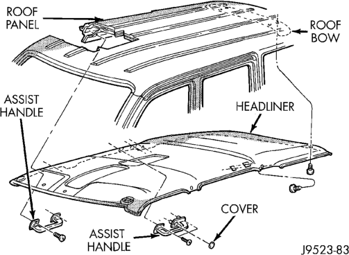
HEADLINER
REMOVAL
CAUTION: The headliner is a one-piece, molded component. It has limited flexibility and must not be bent. Damage possibly will result.
(1) Remove the A, B and C-pillar trim moldings from perimeter of headliner.
(2) If equipped, remove sound bar. Refer to group 8F, Audio Systems for Service procedures.
(3) Remove upper liftgate trim molding. (4) Remove D-pillar trim molding. (5) Remove sunvisors from front of roof panel. Disconnect vanity lamp wiring (if applicable)
(6) Remove assist handles from side of roof rails. (7) Remove push plugs from roof support (Fig. 57). (8) Remove dome/reading lamp or overhead console from center of roof panel.
(9) Remove sunroof pinch welt holding headliner, if equipped (Fig. 58).
(10) With aid of an assistant, remove headliner through liftgate opening.
INSTALLATION
(1) With the aid of an assistant, position headliner in vehicle. (2) Install sunroof pinch welt. (3) Install dome/reading lamp. (4) Install push plugs in roof support. (5) Install sunvisors. (6) Install assist handles. (7) Install A, B, C and D-pillar trim panels.
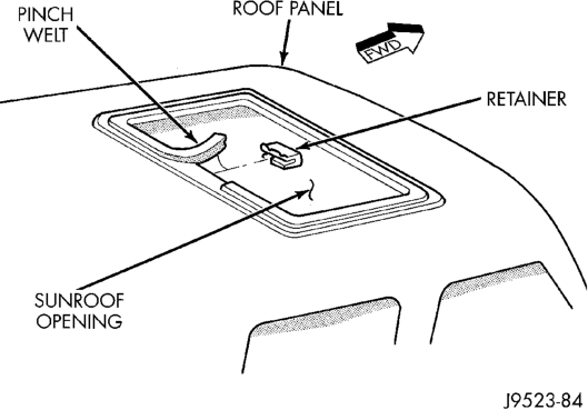
(8) Install liftgate opening upper trim panel. (9) If equipped, install sound bar.
LIFTGATE TRIM PANEL
NOTE:
When removing both trim panels from liftgate, remove lower trim panel first. When installing both trim panels, install the upper trim panel first.
UPPER TRIM PANEL REMOVAL
(1) Remove screws attaching upper trim panel to liftgate (Fig. 59).
(2) Remove screws at upper and lower trim panel overlap.
(3) Disengage the connector for the rear window defogger.
(4) Route the wire harness through the trim panel. (5) Gently, pull trim panel downward. If necessary rotate trim panel away from glass panel to release push-in fasteners.
(6) Use a trim panel removal tool to detach push-in fasteners from liftgate.
UPPER TRIM PANEL INSTALLATION
(1) Position trim panel at liftgate and slide overlapping portions of trim panel under liftgate lower trim panel.
(2) Route the wire harness through the trim panel. (3) Align trim panel push-in fasteners with holes in liftgate inner panel. Press trim panel upward to seat fasteners.
(4) Engage the connector for the rear window defogger.
(5) Install screws at upper and lower trim panel overlap.
(6) Install screws attaching upper trim panel to liftgate.
LOWER TRIM PANEL REMOVAL
(1) Remove screws attaching lower trim panel to liftgate (Fig. 59).
(2) Use a trim panel removal tool to detach push-in fasteners from liftgate.
LOWER TRIM PANEL INSTALLATION
(1) Position trim panel on liftgate. (2) Align trim panel push-in fasteners with holes in liftgate inner panel. Press trim panel inward to seat fasteners.
(3) Install screws attaching lower trim panel to liftgate.
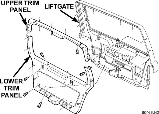
LIFTGATE
REMOVAL
WARNING: DO NOT DISCONNECT THE SUPPORT ROD CYLINDERS WITH THE LIFTGATE CLOSED. THE SUPPORT ROD PISTONS ARE OPERATED BY HIGH PRESSURE GAS. THIS PRESSURE COULD
CAUSE DAMAGE AND/OR PERSONAL INJURY IF THEY ARE REMOVED WHILE THE PISTONS ARE COMPRESSED.
(1) Open liftgate. Support liftgate for ease of repair.
(2) Remove liftgate trim panel. (3) Remove retainer clips that secure support rod cylinders to ball studs (Fig. 60).
(4) Remove support rod cylinders from ball studs. (5) Remove upper support rod retaining screws. Remove support rods.
(6) Disconnect wire harnesses and washer hose from liftgate.
(7) Remove hinge screws at liftgate (Fig. 61). (8) Remove liftgate from vehicle.
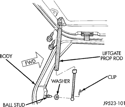
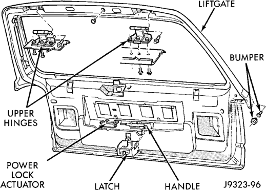
INSTALLATION
(1) Position liftgate on vehicle. Support liftgate. (2) Install hinge screws at liftgate. Tighten hinge screws to 28 N·m (21 ft-lbs) torque
(3) Connect liftgate wire harnesses and washer hose.
(4) Install upper support rod retaining screws. (5) Install support rod cylinders on ball studs. (6) Install liftgate trim panel.
LIFTGATE HINGE
REMOVAL
It is not necessary to remove liftgate to replace one or both hinges. The hinges can be replaced one at a time.
(1) Remove liftgate opening (headliner) upper trim molding.
(2) Disconnect wiring harness to cargo lamp. (3) Remove hinge screws at roof panel (Fig. 62). (4) Remove hinge screws at liftgate. (5) Remove hinge from liftgate.
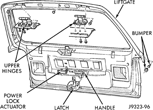
INSTALLATION
(1) Position hinge on liftgate and roof panel. (Use 3My Fast and Firm or equivalent on the hinge to body mating surface as a sealant).
(2) Install and tighten hinge screws at roof panel to 28 N·m (21 ft-lbs) torque.
(3) Install hinge screws at liftgate. Tighten screws to 28 N·m (21 ft-lbs) torque.
(4) Install liftgate opening (headliner) upper trim molding.
LIFTGATE OUTSIDE HANDLE
REMOVAL
(1) Remove liftgate lower trim panel. (2) Remove liftgate latch and actuator linkages. (3) Remove nuts attaching outside handle to liftgate (Fig. 63).
(4) Separate outside handle from liftgate.
INSTALLATION
(1) Position outside handle on liftgate. (2) Install nuts attaching outside handle to liftgate.
(3) Install liftgate latch and actuator linkages. (4) Install liftgate lower trim panel.
LIFTGATE LOCK CYLINDER
For service, refer to the Liftgate Outside Handle Removal/Installation procedure in this group.
LIFTGATE LATCH
REMOVAL
(1) Raise liftgate. Remove liftgate lower trim panel. If necessary refer to service procedure.
(2) Remove latch screws (Fig. 63). (3) Disconnect rod from latch. (4) Disconnect power lock connector from handle, if equipped (Fig. 64).
(5) Remove latch from liftgate.
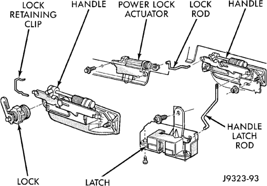
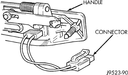
INSTALLATION
(1) Reverse removal procedure. Tighten latch screws to 7 N·m (5 ft. lbs.) torque.
LIFTGATE LATCH STRIKER
REMOVAL
(1) Raise liftgate. (2) Remove latch striker nuts from below scuff plate. Access nuts from under bumper fascia/beam (Fig. 65).
(3) Remove striker, shim and seal plate.
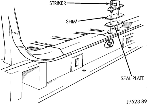
INSTALLATION
(1) Position striker, shim and seal plate on vehicle. (2) Install latch striker nuts. Tighten striker nuts to 54 N·m (40 ft. lbs.) torque.
LIFTGATE OPENING WEATHERSTRIP
REMOVAL
(1) Pull seal away from flange around edge of liftgate opening. Remove it from vehicle.
(2) Clean seal flange as necessary.
INSTALLATION
(1) Position weatherstrip seal in opening with left end of seal at opening centerline. Install seal in a clockwise direction.
(2) Seat installed part of seal. Move from left bottom end of seal to top left half of the seal.
(3) Center and butt seal ends together at centerline.
(4) If necessary, cut surplus from weatherstrip (non-plug end only).
LIFTGATE FLIP-UP GLASS
REMOVAL
WARNING: DO NOT DISCONNECT THE PROP ROD CYLINDERS WITH THE LIFTGATE FLIP-UP GLASS CLOSED. THE PROP ROD PISTONS ARE OPER- ATED BY HIGH PRESSURE GAS. THIS PRESSURE COULD CAUSE DAMAGE AND/OR PERSONAL
INJURY IF THEY ARE REMOVED WHILE THE PIS- TONS ARE COMPRESSED.
(1) Remove liftgate upper trim panel. (2) Open liftgate flip-up glass. Support glass for ease of repair.
(3) Using a small flat blade or equivalent tool, gently pry open the locking caps on the end of the prop rod.
(4) Remove prop rod cylinders from ball studs (Fig. 66).
(5) Remove hinge nuts from liftgate (Fig. 67). (6) Separate flip-up glass from vehicle.
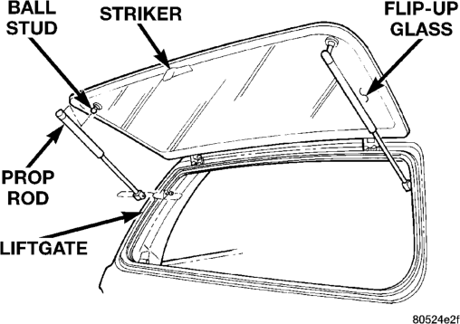
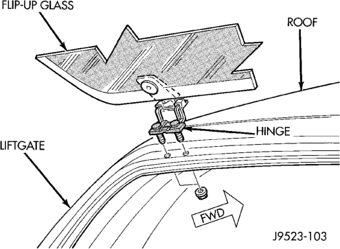
INSTALLATION
(1) Position flip-up glass on liftgate. (2) Install hinge nuts. Hand tighten only. (3) With the glass panel in the open and fully raised position, push glass forward to completely seat the hinges. Tighten hinge nuts to 6 N·m (60 in. lbs.).
(4) Install prop rods onto ball studs and compress locking caps to lock prop rods onto ball studs.
FLIP-UP GLASS SWITCH
REMOVAL
(1) Remove liftgate trim panel. (2) Remove license plate lamp housing nuts from liftgate.
(3) Squeeze switch locking tabs inward to release switch from license plate lamp housing.
(4) Disconnect switch harness connector. (5) Separate switch from housing (Fig. 68).
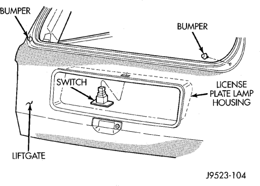
INSTALLATION
(1) Position switch into license plate lamp housing and connect switch harness connector.
(2) Snap switch into place. (3) Install license plate lamp housing. (4) Install liftgate trim panel.
LIFTGATE FLIP-UP GLASS WEATHERSTRIP
REMOVAL
(1) Slowly pull seal away from flange around edge of glass opening. Remove it from vehicle.
(2) Clean seal flange as necessary.
INSTALLATION
(1) Position weatherstrip seal with paint dots aligned with window opening corners.
(2) Seat seal firmly around entire liftgate (Fig. 69). (3) Butt seal ends together and smooth out any remaining length. Weathersrtip break should be 120 mm left of latch opening.
(4) If necessary, cut surplus from weatherstrip (non-plug end only).
LIFTGATE FLIP-UP GLASS LATCH
REMOVAL
(1) Raise liftgate. (2) Remove liftgate lower trim panel.
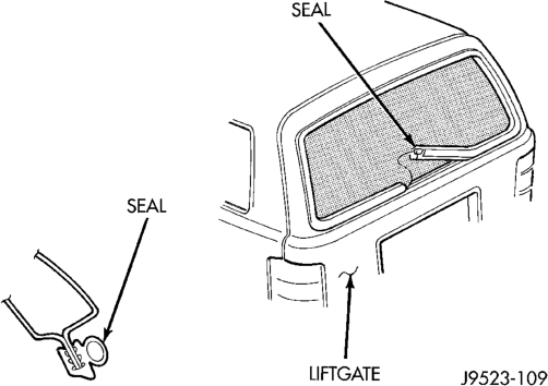
(3) Remove latch nuts (Fig. 70). (4) Disconnect switch connectors. (5) Remove latch from liftgate.
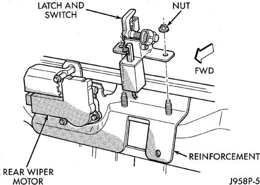
INSTALLATION
(1) Position latch on vehicle, 2.5 mm forward of seal.
(2) Connect switch connectors. (3) Install latch nuts. Tighten to 11 N·m (100 in. lbs.).
(4) Close flip-up glass panel and verify proper operation.
(5) Install liftgate lower trim panel.
LIFTGATE FLIP-UP GLASS LATCH HANDLE/ STRIKER
REMOVAL
(1) Raise flip-up glass. (2) Using a wax pencil or equivalent, make alignment marks on the inside and outside of the glass panel.
(3) Remove handle/striker.
INSTALLATION
(1) Position handle/striker on glass panel and align reference marks.
(2) Install handle/striker. Tighten screws to 6 N·m (60 in. lbs.).
LICENSE PLATE LAMP HOUSING
REMOVAL
(1) Remove liftgate trim panel (2) Remove lamp housing retaining screws from liftgate (Fig. 71).
(3) Disconnect bulb socket from lamp housing. (4) Disconnect Flip-Up glass switch connector, if equipped.
(5) Remove housing from liftgate.
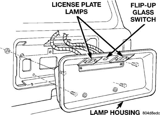
INSTALLATION
(1) Position lamp housing at liftgate. (2) Connect bulb socket to lamp housing. (3) Connect Flip-Up glass switch connector, if equipped.
(4) Install lamp housing retaining screws in liftgate. Tighten screws securely.
(5) Install liftgate trim panel.
QUARTER WINDOW APPLIQUE/AIR EXHAUSTER
REMOVAL
(1) Using a trim stick, carefully pry applique from panel (Fig. 72).
(2) Carefully pry air exhauster from upper quarter panel using a flat blade screwdriver.
INSTALLATION
(1) Reseal air exhauster using foam tape. (2) Install air exhauster on panel.
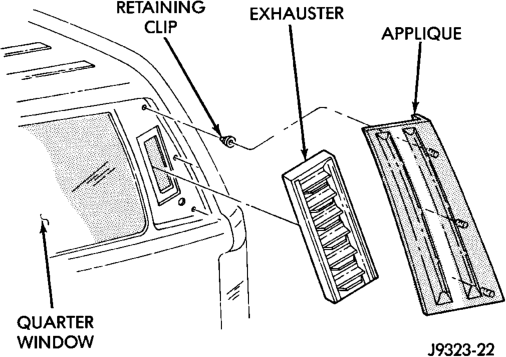
(3) Position applique on panel with retainers aligned. Press applique firmly in place.
LUGGAGE RACK
REMOVAL
(1) Remove slide rail screws (Fig. 73). (2) Remove luggage rack from vehicle roof.
NOTE: The skid strips are attached to roof panel with adhesive.
(3) Loosen each skid strip with a heat gun. (4) Lift one edge of each skid strip with a putty knife and peel it from roof panel. Apply additional heat to any location where a skid strip remains.
(5) Remove original adhesive from roof panel with an all- purpose adhesive removal solution.
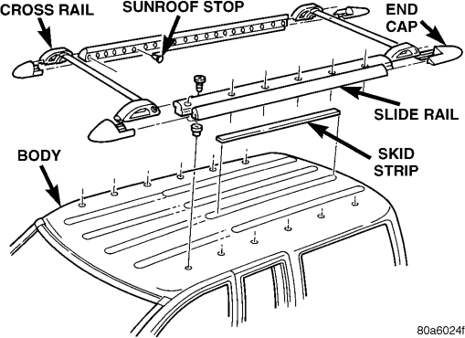
INSTALLATION
(1) Install 3M 06379 double-sided tape on skid strips.
(2) Align each skid strip on roof panel.
(3) Verify that each skid strip is properly aligned. (4) Press each skid strip onto roof panel with a roller.
NOTE: Apply 3M Drip-Chek Sealant (or an equivalent product) to underside of side rail screw heads.
(5) Position luggage rack on roof. (6) Install and tighten slide rail screws to 3 N·m (28 in- lbs) torque.
LUGGAGE RACK—LIMITED PLUS
REMOVAL
(1) Using a small flat blade, carefully pry off riser cover (Fig. 74).
(2) If necessary, depress the lock buttons on the crossbars and slide crossbars inward to expose the screws attaching the side rails to the risers and adapter plates (Fig. 75).
(3) Remove the screws attaching the side rails to the risers and adapter plates (Fig. 76).
(4) Separate the luggage rack from the adapter plates.
(5) Remove the screws attaching the adapter plates to the roof panel.
NOTE: If a crossbar needs to be removed, the forward or rearward risers have to be removed depending on which crossbar is to be serviced.
(6) Separate the adapter plates from the roof panel.
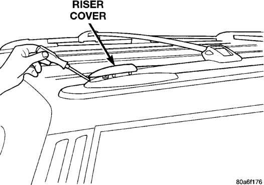
INSTALLATION
(1) Position the adapter plates on the roof panel and install the screws. Ensure that the gasket is properly seated on the adapter plates.
(2) Position the luggage rack on the adapter plates.
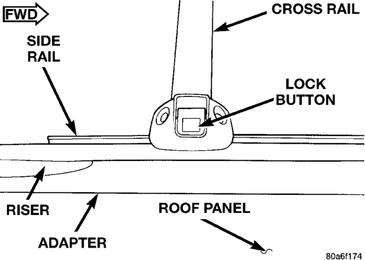
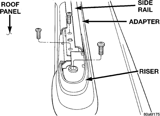
(3) Install the screws attaching the side rails to the risers and adapter plates.
(4) Position the riser covers on the risers and press into place.
ADJUSTMENTS
HOOD ADJUSTMENT
The hood attaching holes are enlarged to aid front, back and side-to-side adjustment.
(1) If hood is low in relation to cowl panel, insert shims between hinge and hood.
(2) Adjust hood bumper (Fig. 77) in or out to adjust hood-to-fender height alignment.
(3) Adjust the hood latch as necessary. Tighten the nuts to 11 N·m (8 ft-lbs) torque after adjustment.
(4) Align latch striker so that striker enters the latch squarely and without binding.
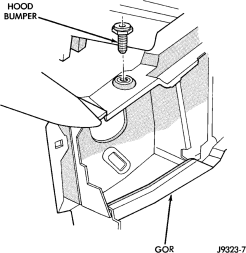
DOOR
Minor adjustment for alignment of the door is made by moving the latch striker.
IN AND OUT
(1) Loosen the latch striker. (2) Tap the latch striker inward if the door character line is outboard of the body character line or tap the latch striker outward if the door character line is inboard of the body character line. (3) Inspect alignment. If correct, tighten striker with 28 N·m (21 ft. lbs.) torque.
UP AND DOWN
(1) Loosen the latch striker. (2) Tap the latch striker downward if the door character line is higher than the body character line or tap the latch striker upward if the door character line is lower than the body character line.
(3) Inspect alignment. If correct, tighten striker with 28 N·m (21 ft. lbs.) torque.
DOOR LATCH ADJUSTMENT
(1) Locate access hole (Fig. 78). (2) Insert a 5/32-inch hex-wrench through hole and into adjustment screw. Loosen screw. (3) Operate outside handle button several times to release any restriction because of mis-alignment.
(4) Tighten adjustment screw to 3 N·m (30 in-lbs) torque.
(5) Test handle button and lock cylinder for proper operation.
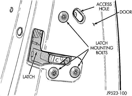
LIFTGATE
The position of liftgate can be adjusted upward or downward by use of slots in the hinge. An inward or outward adjustment is achieved by use of slots in the body. If an inward or outward adjustment is needed, use 3My Fast and Firm or equivalent on the hinge to body mating surface as a sealant.
SPECIFICATIONS
BODY LUBRICANTS
Hood Latch, Release Mechanism and Safety
Latch
Liftgate Support Arms As Required Engine Oil
Liftgate Release Handle (Pivot and Slide
1 = Mopar Wheel Bearing Grease (High Temp) 2 = Mopar Multi-Mileage Lubricant 3 = Mopar Spray White Lube 4 = Mopar Lock Cylinder Lubricant
SPECIAL TOOLS
Body
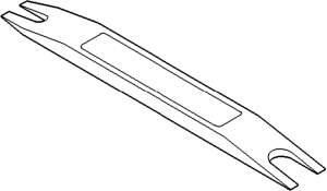
COMPONENT SERVICE INTERVAL LUBRICANT
Door Hinges As Required Multi-Purpose Grease NLGI GC-LB
(Water Resistant) (1)
Door Latches As Required Multi-Purpose Grease NLGI GC-LB
(Water Resistant) (1)
As Required (When Performing
Multi-Purpose Grease NLGI GC-LB 2
Other Underhood
EP (2)
Service)
Hood Hinges As Required Engine Oil
Seat Track and Release Mechanism As Required Multi-Purpose Grease NLGI GC-LB 2
EP (2)
Liftgate Hinge As Required Multi-Purpose Grease NLGI GC-LB 2
EP (2)
Liftgate Latches As Required White Spray Lubricant (3)
Contact Surfaces) As Required Multi-Purpose Grease NLGI GC-LB 2
EP (2)
Window System Components As Required White Spray Lubricant (3)
Lock Cylinders Twice a Year Lock-Cylinder Lubricant (4)
Parking Brake Mechanism As Required Multi-Purpose Grease NLGI GC-LB 2
EP (1)