Audio Systems — 1998 Jeep Grand Cherokee ZJ Export Service Manual
Pages 443–457 · 15 pages · 1 words repaired
Detection (CCD) data bus network through a separate two-way wire harness connector. The CCD data bus network allows the sharing of sensor information. This helps to reduce wire harness complexity, internal controller hardware, and component sensor current loads. At the same time, this system provides increased reliability, enhanced diagnostics, and allows the addition of many new feature capabilities.
Radios connected to the CCD data bus network in vehicles equipped with the optional Vehicle Information Center (VIC) have a clock synchronization feature. The VIC clock display is automatically updated to the setting shown on the radio clock through a message sent on the CCD data bus by the radio. Refer to Group 8E - Instrument Panel Systems for more information on the VIC module.
In addition, radios connected to the CCD data bus have several audio system functions that can be diagnosed using a DRB scan tool. Refer to the proper Diagnostic Procedures manual for more information on DRB testing of the audio systems.
The radio can only be serviced by an authorized radio repair station. Refer to the latest Warranty Policies and Procedures manual for a current listing of authorized radio repair stations.
For more information on radio features, setting procedures, and control functions refer to the owner's manual in the vehicle glove box.
REMOTE RADIO SWITCH
A remote radio control switch option is available on Grand Cherokee Limited models with the AM/FM/ cassette/5-band graphic equalizer with CD changer control feature (RBN sales code), or the AM/FM/CD/ cassette/3-band graphic equalizer (RAZ sales code) radio receivers. Two rocker-type switches are mounted on the back (instrument panel side) of the steering wheel spokes. The switch on the left spoke is the seek switch and has seek up, seek down, and preset station advance functions. The switch on the right spoke is the volume control switch and has volume up, and volume down functions.
These switches are resistor multiplexed units that are hard-wired to the Body Control Module (BCM) through the clockspring. The BCM sends the proper messages on the Chrysler Collision Detection (CCD) data bus network to the radio receiver. For diagnosis of the BCM or the CCD data bus, the use of a DRB scan tool and the proper Diagnostic Procedures manual are recommended. For more information on the operation of the remote radio switch controls, refer to the owner's manual in the vehicle glove box.
BODY CONTROL MODULE
A Body Control Module (BCM) is used on this model to control and integrate many of the electronic functions and features included on the vehicle. The BCM contains a central processing unit and interfaces with other modules in the vehicle on the Chrysler Collision Detection (CCD) data bus network.
The CCD data bus network allows the sharing of sensor information. This helps to reduce wire harness complexity, reduce internal controller hardware, and reduce component sensor current loads. At the same time, this system provides increased reliability, enhanced diagnostics, and allows the addition of many new feature capabilities.
One of the functions and features that the BCM supports and controls, is the remote radio switches on vehicles so equipped. The BCM receives hardwired resistor multiplexed inputs from the remote radio switches. The programming in the BCM allows it to process those inputs and send the proper messages to the radio over the CCD data bus to control the radio volume, station seek, and preset station advance functions.
The BCM is mounted under the driver side outboard end of the instrument panel, behind the instrument panel support armature and below the outboard switch pod. Refer to Group 8E - Instrument Panel Systems for the removal and installation procedures. For diagnosis of the BCM or the CCD data bus, the use of a DRB scan tool and the proper Diagnostic Procedures manual are recommended. The BCM can only be serviced by an authorized electronic repair station. Refer to the latest Warranty Policies and Procedures manual for a current listing of authorized electronic repair stations.
IGNITION-OFF DRAW FUSE
All vehicles are equipped with an Ignition-Off Draw (IOD) fuse that is removed when the vehicle is shipped from the factory. This fuse feeds various accessories that require battery current when the ignition switch is in the Off position, including the clock and radio station preset memory functions. The fuse is removed to prevent battery discharge during vehicle storage.
When removing or installing the IOD fuse, it is important that the ignition switch be in the Off position. Failure to place the ignition switch in the Off position can cause the radio display to become scrambled when the IOD fuse is removed and replaced. Removing and replacing the IOD fuse again, with the ignition switch in the Off position, will correct the scrambled display condition.
The IOD fuse should be checked if the radio is inoperative. The IOD fuse is located in the Power Distribution Center (PDC). Refer to the PDC label for IOD fuse identification and location.
SPEAKER
The only speaker system offered with the base AM/FM/cassette radio receiver (RAS sales code) includes four full-range speakers, one mounted in each of the four doors. This is also the standard equipment speaker system offered with the AM/FM/ CD/cassette/3-band graphic equalizer (RAZ sales code).
Optional for the RAZ sales code radio, and standard for all other radios (except RAS sales code) is the Infinity Gold premium speaker and 120 watt amplifier package. This package uses an Infinity amplifier mounted on the floor beneath the rear seat cushion on the driver side of the vehicle. The package includes an Infinity coaxial full-range speaker mounted in each rear door, an Infinity woofer speaker mounted in each front door, and an Infinity tweeter mounted at each outboard end of the instrument panel top cover.
The standard equipment speaker system for the Limited Plus package is the Infinity Gold premium speaker and 180 watt amplifier package. In addition to the increased amplifier output, this package adds a sound bar mounted on the inside roof headliner, just forward of the liftgate opening. This package uses the same Infinity speakers as the 120 watt amplifier package in the front doors and the instrument panel, but uses Infinity woofers in the rear doors. In addition, the sound bar houses two Infinity mid-range speakers and two Infinity tweeters, for a total of ten system speakers.
ANTENNA
All models use a fixed-length stainless steel rodtype antenna mast, installed on the right front fender of the vehicle. The antenna mast is connected to the center wire of the coaxial antenna cable, and is not grounded to any part of the vehicle.
To eliminate static, the antenna base must have a good ground. The coaxial antenna cable shield (the outer wire mesh of the cable) is grounded to the antenna base and the radio chassis.
The antenna coaxial cable has an additional disconnect, located near the right end of the instrument panel at the right cowl side inner panel. This additional disconnect allows the instrument panel assembly to be removed and installed without removing the radio.
The factory-installed Electronically Tuned Radios (ETRs) automatically compensate for radio antenna trim. Therefore, no antenna trimmer adjustment is required or possible when replacing the receiver or the antenna.
RADIO NOISE SUPPRESSION
Radio Frequency Interference (RFI) and Electro- Magnetic Interference (EMI) noise suppression is accomplished primarily through circuitry internal to the radio receivers. These internal suppression devices are only serviced as part of the radio receiver.
External suppression devices that are serviced, and should be checked in the case of RFI or EMI noise complaints, include the following:
• Radio antenna base ground • Radio chassis ground wire, strap, or bracket • Engine-to-body ground strap (if the vehicle is so equipped)
• Cab-to-bed ground strap (if the vehicle is so equipped)
• Heater core ground strap (if the vehicle is so equipped)
• Resistor-type spark plugs • Radio suppression-type secondary ignition wiring. In addition, if the source of RFI or EMI noise is identified as a component on the vehicle (i.e., generator, blower motor, etc.), the ground path for that component should be checked. If excessive resistance is found in that circuit, repair that circuit as required before considering any component replacement.
If the source of the noise is identified as two-way mobile radio or telephone equipment, check the equipment installation for the following:
• Power connections should be made directly to the battery, and fused as closely to the battery as possible.
• The antenna should be mounted on the roof or toward the rear of the vehicle. Remember that magnetic antenna mounts on the roof panel can adversely affect the operation of an overhead console compass, if the vehicle is so equipped. • The antenna cable should be fully shielded coaxial cable, should be as short as is practical, and should be routed away from the factory-installed vehicle wire harnesses whenever possible.
• The antenna and cable must be carefully matched to ensure a low Standing Wave Ratio (SWR).
Fleet vehicles are available with an extra-cost RFI- suppressed Powertrain Control Module (PCM). This unit reduces interference generated by the PCM on some radio frequencies used in two-way radio communications. However, this unit will not resolve complaints of RFI in the commercial AM or FM radio frequency ranges.
DIAGNOSIS AND TESTING
AUDIO SYSTEM
WARNING: ON VEHICLES EQUIPPED WITH AIR- BAGS, REFER TO GROUP 8M - PASSIVE RESTRAINT SYSTEMS BEFORE ATTEMPTING ANY STEERING WHEEL, STEERING COLUMN, OR INSTRUMENT PANEL COMPONENT DIAGNOSIS OR SERVICE. FAILURE TO TAKE THE PROPER PRE- CAUTIONS COULD RESULT IN ACCIDENTAL AIR- BAG DEPLOYMENT AND POSSIBLE PERSONAL INJURY.
RADIO
If the vehicle is equipped with remote radio switches located on the backs of the steering wheel spokes, and the problem being diagnosed is related to one of the symptoms listed below, be certain to check the remote radio switches and circuits as described in this group, prior to attempting radio diagnosis or repair.
• Stations changing with no remote radio switch input • Radio memory presets not working properly • Volume changes with no remote radio switch input • Remote radio switch buttons taking on other functions
• CD player skipping tracks • Remote radio switch inoperative. For circuit descriptions and diagrams, refer to 8W-47 - Audio System in Group 8W - Wiring Diagrams.
WARNING: ON VEHICLES EQUIPPED WITH AIR- BAGS, REFER TO GROUP 8M - PASSIVE RESTRAINT SYSTEMS BEFORE ATTEMPTING ANY STEERING WHEEL, STEERING COLUMN, OR INSTRUMENT PANEL COMPONENT DIAGNOSIS OR SERVICE. FAILURE TO TAKE THE PROPER PRE- CAUTIONS COULD RESULT IN ACCIDENTAL AIR- BAG DEPLOYMENT AND POSSIBLE PERSONAL INJURY.
CAUTION: The speaker output of the radio is a “floating ground” system. Do not allow any speaker lead to short to ground, as damage to the radio may result.
(1) Check the fuse(s) in the junction block and the Power Distribution Center (PDC). If OK, go to Step 2. If not OK, repair the shorted circuit or component as required and replace the faulty fuse(s).
(2) Check for battery voltage at the fuse in the PDC. If OK, go to Step 3. If not OK, repair the open circuit to the battery as required.
(3) Turn the ignition switch to the On position. Check for battery voltage at the fuse in the junction block. If OK, go to Step 4. If not OK, repair the open circuit to the ignition switch as required.
(4) Turn the ignition switch to the Off position. Disconnect and isolate the battery negative cable. Remove the radio, but do not unplug the radio wire harness connectors. Check for continuity between the radio chassis and a good ground. There should be continuity. If OK, go to Step 5. If not OK, repair the open radio chassis ground circuit as required.
(5) Connect the battery negative cable. Turn the ignition switch to the On position. Check for battery voltage at the fused ignition switch output (accessory/run) circuit cavity of the left (gray) radio wire harness connector. If OK, go to Step 6. If not OK, repair the open circuit as required.
(6) Turn the ignition switch to the Off position. Check for battery voltage at the fused B(+) circuit cavity of the left (gray) radio wire harness connector. If OK, replace the faulty radio. If not OK, repair the open circuit to the Ignition-Off Draw (IOD) fuse as required.
REMOTE RADIO SWITCH
WARNING: ON VEHICLES EQUIPPED WITH AIR- BAGS, REFER TO GROUP 8M - PASSIVE RESTRAINT SYSTEMS BEFORE ATTEMPTING ANY STEERING WHEEL, STEERING COLUMN, OR INSTRUMENT PANEL COMPONENT DIAGNOSIS OR SERVICE. FAILURE TO TAKE THE PROPER PRE- CAUTIONS COULD RESULT IN ACCIDENTAL AIR- BAG DEPLOYMENT AND POSSIBLE PERSONAL INJURY.
(1) Disconnect and isolate the battery negative cable. Wait two minutes for the airbag system capacitor to discharge before further service. (2) Remove the remote radio switch(es) from the steering wheel.
CONDITION POSSIBLE CAUSE CORRECTION
NO AUDIO. 1. Fuse faulty. 2. Radio connector faulty. 3. Wiring faulty. 4. Ground faulty. 5. Radio faulty. 6. Speakers faulty.
NO DISPLAY. 1. Fuse faulty. 2. Radio connector faulty. 3. Wiring faulty. 4. Ground faulty. 5. Radio faulty.
CLOCK WILL NOT KEEP SET TIME.
1. Fuse faulty. 2. Radio connector faulty. 3. Wiring faulty. 4. Ground faulty. 5. Radio faulty.
POOR RADIO RECEPTION.
1. Antenna faulty. 2. Ground faulty. 3. Radio faulty.
NO/POOR TAPE OPERATION.
1. Faulty tape. 2. Foreign objects behind tape door. 3. Dirty cassette tape head. 4. Faulty tape deck.
NO COMPACT DISC OPERATION
1. Faulty CD. 2. Foreign material on CD. 3. Condensation on CD or optics. 4. Faulty CD player.
Audio System Diagnosis
1. Check radio fuses in junction block. Replace fuses, if required. 2. Check for loose or corroded radio connector. Repair, if required. 3. Check for battery voltage at radio connector. Repair wiring, if required. 4. Check for continuity between radio chassis and a known good ground. There should be continuity. Repair ground, if required. 5. Exchange or replace radio, if required. 6. See speaker diagnosis, in this group.
1. Check radio fuses in junction block. Replace fuses, if required. 2. Check for loose or corroded radio connector. Repair, if required. 3. Check for battery voltage at radio connector. Repair wiring, if required. 4. Check for continuity between radio chassis and a known good ground. There should be continuity. Repair ground, if required. 5. Exchange or replace radio, if required.
1. Check ignition-off draw fuse. Replace fuse, if required. 2. Check for loose or corroded radio connector. Repair, if required. 3. Check for battery voltage at radio connector. Repair wiring, if required. 4. Check for continuity between radio chassis and a known good ground. There should be continuity. Repair ground, if required. 5. Exchange or replace radio, if required.
1. See antenna diagnosis, in this group. Repair or replace antenna, if required. 2. Check for continuity between radio chassis and a known good ground. There should be continuity. Repair ground, if required. 3. Exchange or replace radio, if required.
1. Insert known good tape and test operation. 2. Remove foreign objects and test operation. 3. Clean head with Mopar Cassette Head Cleaner. 4. Exchange or replace radio, if required.
1. Insert known good CD and test operation. 2. Clean CD and test operation. 3. Allow temperature of vehicle interior to stabilize and test operation. 4. Exchange or replace radio, if required.
(3) Use an ohmmeter to check the switch resistance as shown in the Remote Radio Switch Test chart.
Remote Radio Switch Test
Switch Position Resistance
Volume Up 7320 Ohms
Volume Down 1210 Ohms
Seek Up 4530 Ohms
Seek Down 2050 Ohms
Pre-Set Station Advance 10 Ohms
(4) If the switch resistance checks OK, go to Step 5. If not OK, replace the faulty switch.
(5) Check for continuity between the ground circuit cavity of the switch wire harness connector and a good ground. There should be continuity. If OK, go to Step 6. If not OK, repair the open circuit as required.
(6) Unplug the 24-way white wire harness connector from the Body Control Module (BCM). Check for continuity between the radio control mux circuit cavity of the remote radio switch wire harness connector and a good ground. There should be no continuity. If OK, go to Step 7. If not OK, repair the short circuit as required.
(7) Check for continuity between the radio control mux circuit cavities of the remote radio switch wire harness connector and the BCM wire harness connector. There should be continuity. If OK, refer to the proper Diagnostic Procedures manual to test the BCM and the CCD data bus. If not OK, repair the open circuit as required.
SPEAKER
For circuit descriptions and diagrams, refer to 8W-47 - Audio System in Group 8W - Wiring Diagrams.
WARNING: ON VEHICLES EQUIPPED WITH AIR- BAGS, REFER TO GROUP 8M - PASSIVE RESTRAINT SYSTEMS BEFORE ATTEMPTING ANY STEERING WHEEL, STEERING COLUMN, OR INSTRUMENT PANEL COMPONENT DIAGNOSIS OR SERVICE. FAILURE TO TAKE THE PROPER PRE- CAUTIONS COULD RESULT IN ACCIDENTAL AIR- BAG DEPLOYMENT AND POSSIBLE PERSONAL INJURY.
CAUTION: The speaker output of the radio is a “floating ground” system. Do not allow any speaker lead to short to ground, as damage to the radio may result.
(1) Turn the ignition switch to the On position. Turn the radio on. Adjust the balance and fader controls to check the performance of each individual speaker. Note the speaker locations that are not performing correctly. Go to Step 2.
(2) Turn the radio off. Turn the ignition switch to the Off position. Disconnect and isolate the battery negative cable. Remove the radio from the instrument panel. If the vehicle is equipped with the Infinity Gold speaker package, also unplug the wire harness connectors at the amplifier. Check both the speaker feed (+) circuit and return (–) circuit cavities for the inoperative speaker location(s) at the radio wire harness connectors for continuity to ground. In each case, there should be no continuity. If OK, go to Step 3. If not OK, repair the shorted speaker circuit(s) as required.
(3) If the vehicle is equipped with the Infinity Gold speaker package, go to Step 6. If the vehicle is equipped with the standard speaker system, check the resistance between the speaker feed (+) circuit and return (–) circuit cavities of the radio wire harness connectors for the inoperative speaker location(s). The meter should read between 3 and 8 ohms (speaker resistance). If OK, go to Step 4. If not OK, go to Step 5.
(4) Install a known good radio. Connect the battery negative cable. Turn the ignition switch to the On position. Turn on the radio and test the speaker operation. If OK, replace the faulty radio. If not OK, turn the radio off, turn the ignition switch to the Off position, disconnect and isolate the battery negative cable, remove the test radio, and go to Step 5.
(5) Unplug the speaker wire harness connector at the inoperative speaker. Check for continuity between the speaker feed (+) circuit cavities of the radio wire harness connector and the speaker wire harness connector. Repeat the check between the speaker return (–) circuit cavities of the radio wire harness connector and the speaker wire harness connector. In each case, there should be continuity. If OK, replace the faulty speaker. If not OK, repair the open circuit(s) as required.
(6) For each inoperative speaker location, check for continuity between the speaker feed (+) circuit cavities of the radio wire harness connectors and the amplifier wire harness connectors. Repeat the check for each inoperative speaker location between the speaker return (–) circuit cavities of the radio wire harness connectors and the amplifier wire harness connectors. In each case, there should be continuity. If OK, go to Step 7. If not OK, repair the open circuit as required.
(7) Check for continuity between the two ground circuit cavities of the amplifier wire harness connector and a good ground. There should be continuity. If
OK, go to Step 8. If not OK, repair the open circuit(s) as required.
(8) Check the amplifier fuse in the junction block. If OK, go to Step 9. If not OK, repair the shorted circuit or component as required and replace the faulty fuse.
(9) Install the radio. Connect the battery negative cable. Check for battery voltage at the amplifier fuse in the junction block. If OK, go to Step 10. If not OK, repair the open circuit to the PDC as required.
(10) Check for battery voltage at the two fused B(+) circuit cavities of the amplifier wire harness connector. If OK, go to Step 11. If not OK, repair the open circuit to the fuse in the junction block as required.
(11) Turn the ignition switch to the On position. Turn the radio on. Check for battery voltage at the radio 12 volt output circuit cavity of the amplifier wire harness connector. If OK, go to Step 12. If not OK, repair the open circuit to the radio as required.
(12) Turn the radio off. Turn the ignition switch to the Off position. Disconnect and isolate the battery negative cable. For each inoperative speaker location, check both the amplified feed (+) circuit and the amplified return (–) circuit cavities of the amplifier wire harness connectors for continuity to ground. In each case there should be no continuity. If OK, go to Step 13. If not OK, repair the short circuit as required.
(13) For each inoperative speaker location, check the resistance between the amplified feed (+) circuit and the amplified return (–) circuit cavities of the amplifier wire harness connectors. The meter should read between 3 and 8 ohms (speaker resistance). If OK, replace the faulty amplifier. If not OK, go to Step 14.
(14) Unplug the speaker wire harness connector at the inoperative speaker. Check for continuity between the amplified feed (+) circuit cavities of the speaker wire harness connector and the amplifier wire harness connector. Repeat the check between the amplified return (–) circuit cavities of the speaker wire harness connector and the amplifier wire harness connector. In each case there should be continuity. If OK, replace the faulty speaker. If not OK, repair the open circuit as required.
ANTENNA
WARNING: ON VEHICLES EQUIPPED WITH AIR- BAGS, REFER TO GROUP 8M - PASSIVE RESTRAINT SYSTEMS BEFORE ATTEMPTING ANY STEERING WHEEL, STEERING COLUMN, OR INSTRUMENT PANEL COMPONENT DIAGNOSIS OR SERVICE. FAILURE TO TAKE THE PROPER PRE- CAUTIONS COULD RESULT IN ACCIDENTAL AIR-
BAG DEPLOYMENT AND POSSIBLE PERSONAL INJURY.
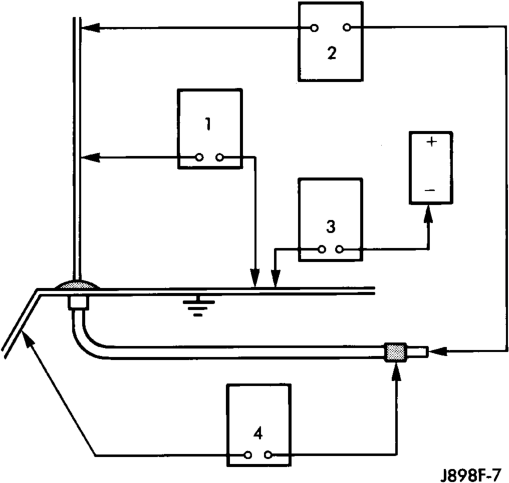
The following four tests are used to diagnose the antenna with an ohmmeter:
• Test 1 - Mast to ground test • Test 2 - Tip-of-mast to tip-of-conductor test • Test 3 - Body ground to battery ground test • Test 4 - Body ground to coaxial shield test. The ohmmeter test lead connections for each test are shown in Antenna Tests (Fig. 1).
NOTE: This model has a two-piece antenna coaxial cable. Tests 2 and 4 must be conducted in two steps to isolate a coaxial cable problem; from the coaxial cable connection under the right end of the instrument panel near the right cowl side panel to the antenna base, and then from the coaxial cable connection to the radio chassis connection.
TEST 1
Test 1 determines if the antenna mast is insulated from the base. Proceed as follows:
(1) Unplug the antenna coaxial cable connector from the radio chassis and isolate.
(2) Connect one ohmmeter test lead to the tip of the antenna mast. Connect the other test lead to the antenna base. Check for continuity.
(3) There should be no continuity. If continuity is found, replace the faulty or damaged antenna base and cable assembly.
TEST 2
Test 2 checks the antenna for an open circuit as follows:
(1) Unplug the antenna coaxial cable connector from the radio chassis.
(2) Connect one ohmmeter test lead to the tip of the antenna mast. Connect the other test lead to the center pin of the antenna coaxial cable connector.
(3) Continuity should exist (the ohmmeter should only register a fraction of an ohm). High or infinite resistance indicates damage to the base and cable assembly. Replace the faulty base and cable, if required.
TEST 3
Test 3 checks the condition of the vehicle body ground connection. This test should be performed with the battery positive cable removed from the battery. Disconnect both battery cables, the negative cable first. Reconnect the battery negative cable and perform the test as follows:
(1) Connect one ohmmeter test lead to the vehicle fender. Connect the other test lead to the battery negative post.
(2) The resistance should be less than one ohm. (3) If the resistance is more than one ohm, check the braided ground strap connected to the engine and the vehicle body for being loose, corroded, or damaged. Repair the ground strap connection, if required.
TEST 4
Test 4 checks the condition of the ground between the antenna base and the vehicle body as follows:
(1) Connect one ohmmeter test lead to the vehicle fender. Connect the other test lead to the outer crimp on the antenna coaxial cable connector.
(2) The resistance should be less then one ohm. (3) If the resistance is more then one ohm, clean and/or tighten the antenna base to fender mounting hardware.
RADIO FREQUENCY INTERFERENCE
WARNING: ON VEHICLES EQUIPPED WITH AIR- BAGS, REFER TO GROUP 8M - PASSIVE RESTRAINT SYSTEMS BEFORE ATTEMPTING ANY STEERING WHEEL, STEERING COLUMN, OR INSTRUMENT PANEL COMPONENT DIAGNOSIS OR SERVICE. FAILURE TO TAKE THE PROPER PRE- CAUTIONS COULD RESULT IN ACCIDENTAL AIR- BAG DEPLOYMENT AND POSSIBLE PERSONAL INJURY.
Inspect the ground connections at the following: • Blower motor • Electric fuel pump • Generator • Ignition module • Wiper motor • Antenna coaxial ground
• Radio ground • Body-to-engine braided ground strap (if the vehicle is so equipped).
Clean, tighten, or repair the connections as required.
Also inspect the following secondary ignition system components, as described in Group 8D - Ignition Systems:
• Spark plug wire routing and condition • Distributor cap and rotor • Ignition coil • Spark plugs. Reroute the spark plug wires or replace the faulty components as required.
REMOVAL AND INSTALLATION
RADIO
WARNING: ON VEHICLES EQUIPPED WITH AIR- BAGS, REFER TO GROUP 8M - PASSIVE RESTRAINT SYSTEMS BEFORE ATTEMPTING ANY STEERING WHEEL, STEERING COLUMN, OR INSTRUMENT PANEL COMPONENT DIAGNOSIS OR SERVICE. FAILURE TO TAKE THE PROPER PRE- CAUTIONS COULD RESULT IN ACCIDENTAL AIR- BAG DEPLOYMENT AND POSSIBLE PERSONAL INJURY.
(1) Disconnect and isolate the battery negative cable.
(2) Using a trim stick or another suitable wide flat-bladed tool, gently pry around the perimeter edges of both instrument panel switch pod bezels to release the snap clip retainers. Remove both bezels from the instrument panel.
(3) Remove the ten screws that secure the cluster bezel to the instrument panel (Fig. 2).
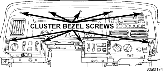
(4) Pull the cluster bezel rearward and move it to the outboard side of the steering wheel to remove it from the instrument panel.
(5) Remove the two screws that secure the radio face plate to the instrument panel (Fig. 3).
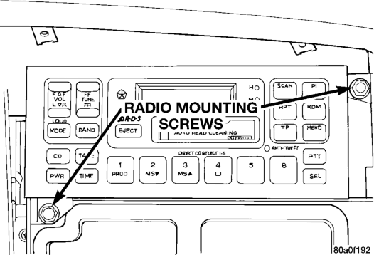
(6) Pull the radio out from the instrument panel far enough to access the wire harness connectors and the antenna coaxial cable connector (Fig. 4).
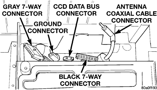
(7) Unplug the wire harness connectors and the antenna coaxial cable connector from the rear of the radio.
(8) If the vehicle is so equipped, remove the screw that secures the ground strap to the radio chassis.
(9) Remove the radio from the instrument panel. (10) Reverse the removal procedures to install. Tighten the radio mounting screws to 5 N·m (45 in. lbs.). Tighten the cluster bezel mounting screws to 2.2 N·m (20 in. lbs.).
REMOTE RADIO SWITCH
WARNING: ON VEHICLES EQUIPPED WITH AIR- BAGS, REFER TO GROUP 8M - PASSIVE RESTRAINT SYSTEMS BEFORE ATTEMPTING ANY STEERING WHEEL, STEERING COLUMN, OR INSTRUMENT PANEL COMPONENT DIAG- NOSIS OR SERVICE. FAILURE TO TAKE THE PROPER PRECAUTIONS COULD RESULT IN ACCIDENTAL AIRBAG DEPLOYMENT AND POS- SIBLE PERSONAL INJURY.
(1) Disconnect and isolate the battery negative cable. Wait two minutes for the airbag system capacitor to discharge before further service. (2) From the underside of the steering wheel, remove the three screws that secure the driver side airbag module to the steering wheel (Fig. 5).
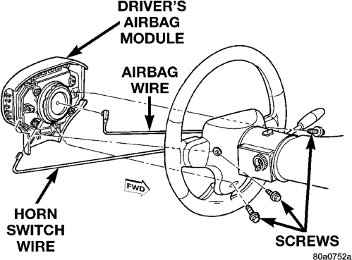
(3) Pull the airbag module away from the steering wheel far enough to access the wire harness connectors on the back of the airbag module.
(4) Unplug the airbag module and horn switch wire harness connectors from the back of the airbag module.
(5) Remove the driver side airbag module from the vehicle.
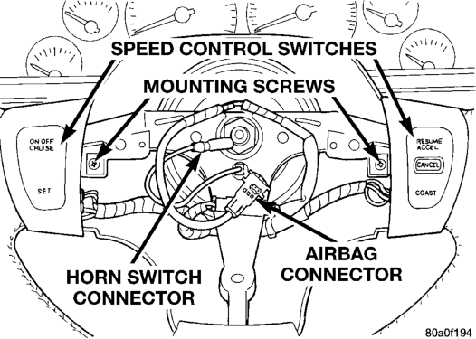
(6) Remove the screws that secure the vehicle speed control switches to the steering wheel, and lower the switches from the steering wheel spokes (Fig. 6).
Install
(7) Remove the two screws that secure the remote radio switch to the steering wheel spoke (Fig. 7).
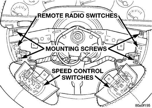
(8) Unplug the wire harness connector from the remote radio switch.
(9) Remove the remote radio switch from the steering wheel. (10) Reverse the removal procedures to install. Tighten the airbag module mounting screws to 10.2 N·m (90 in. lbs.).
AMPLIFIER
(1) Disconnect and isolate the battery negative cable.
(2) Disengage the left rear seat cushion latch by pulling upward on the release strap. Tilt the seat cushion forward.
(3) Lift the carpeting in the under-seat area as required to access the amplifier.
(4) Unplug the two wire harness connectors from the amplifier.
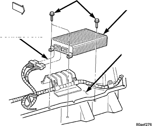
(5) Remove the three screws that secure the amplifier to the floor panel (Fig. 8).
(6) Remove the amplifier from the floor panel. (7) Reverse the removal procedures to install. Tighten the amplifier mounting screws to 2.8 N·m (25 in. lbs.).
SPEAKER
INSTRUMENT PANEL
WARNING: ON VEHICLES EQUIPPED WITH AIR- BAGS, REFER TO GROUP 8M - PASSIVE RESTRAINT SYSTEMS BEFORE ATTEMPTING ANY STEERING WHEEL, STEERING COLUMN, OR INSTRUMENT PANEL COMPONENT DIAGNOSIS OR SERVICE. FAILURE TO TAKE THE PROPER PRE- CAUTIONS COULD RESULT IN ACCIDENTAL AIR-
BAG DEPLOYMENT AND POSSIBLE PERSONAL INJURY.
(1) Disconnect and isolate the battery negative cable.
(2) Using a trim stick or another suitable wide flat-bladed tool, gently pry the cowl top trim panel off of the instrument panel top pad (Fig. 9).
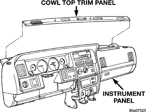
(3) Pull the trim panel up far enough to access and unplug the wire harness connector for the solar sensor, or to remove the solar sensor from the cowl top trim, if the vehicle is so equipped.
(4) Remove the cowl top trim panel from the instrument panel. (5) Unplug the speaker wire harness connector. (6) Remove the two screws that secure the speaker to the instrument panel (Fig. 10).
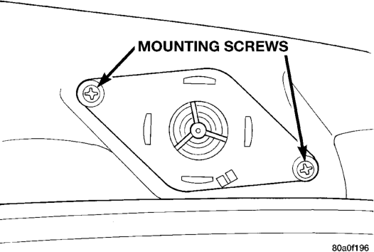
(7) Remove the speaker from the instrument panel.
(8) Reverse the removal procedures to install. Tighten the speaker mounting screws to 1.1 N·m (10 in. lbs.).
FRONT DOOR
(1) Disconnect and isolate the battery negative cable.
(2) Remove the bezel near the inside door latch release handle by inserting a straight-bladed screwdriver in the notched end of the bezel and prying gently upwards.
(3) Remove the screw located beneath the bezel that secures the front door trim panel to the inner door panel (Fig. 11).
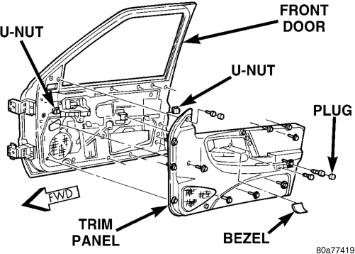
(4) Remove the trim cap and screw near the rear of the front door armrest.
(5) Remove the trim cap and screw at the upper front corner of the front door trim panel.
(6) Remove the screw located above the front door speaker grille on the front door trim panel.
(7) Using a trim stick or another suitable wide flat-bladed tool, gently pry the front door trim panel away from the door around the perimeter to release the trim panel retainers.
NOTE: To aid in the removal of the trim panel, start at the bottom of the panel.
(8) Pull the front door trim panel away from the inner door panel far enough to access and unplug the wire harness connectors from the door module and, if the vehicle is so equipped, from the front door courtesy lamp.
(9) Remove the three screws that secure the speaker to the lower front corner of the inner door panel (Fig. 12).
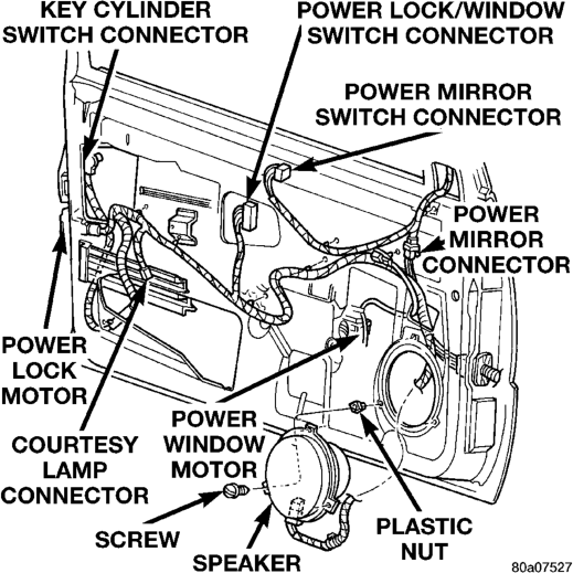
(10) Pull the speaker away from the inner door panel far enough to access and unplug the speaker wire harness connector.
(11) Remove the speaker from the door. (12) Reverse the removal procedures to install. Tighten the hardware as follows:
• Speaker mounting screws - 1.1 N·m (10 in. lbs.) • Trim panel mounting screws - 1.3 N·m (12 in. lbs.).
REAR DOOR
(1) Disconnect and isolate the battery negative cable.
(2) Remove the bezel near the inside door latch release handle by inserting a straight-bladed screwdriver in the notched end of the bezel and prying gently upwards.
(3) Remove the screw located beneath the bezel that secures the rear door trim panel to the inner door panel (Fig. 13).
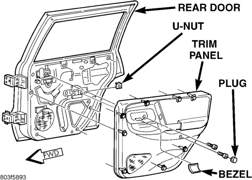
(4) Remove the trim cap and screw near the rear of the rear door armrest.
(5) Using a trim stick or another suitable wide flat-bladed tool, gently pry the rear door trim panel away from the door around the perimeter to release the trim panel retainers.
NOTE: To aid in the removal of the trim panel, start at the bottom of the panel.
(6) Pull the rear door trim panel away from the inner door panel far enough to access and unplug the wire harness connector from the power window switch.
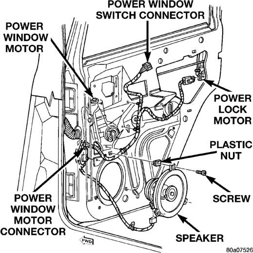
(7) Remove the three screws that secure the speaker to the lower front corner of the inner door panel (Fig. 14).
(8) Pull the speaker away from the inner door panel far enough to access and unplug the speaker wire harness connector.
(9) Remove the speaker from the door. (10) Reverse the removal procedures to install. Tighten the hardware as follows:
• Speaker mounting screws - 1.1 N·m (10 in. lbs.) • Trim panel mounting screws - 1.3 N·m (12 in. lbs.).
SOUND BAR
TWEETER
(1) Remove the sound bar from the vehicle. See Sound Bar in this group for the procedures.
(2) Unplug the sound bar wire harness connector from the tweeter.
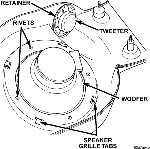
(3) From the inside of the sound bar, use a pair of side cutters to cut and remove the push-nut type retainer that secures the tweeter to the sound bar (Fig. 15).
(4) From the inside of the sound bar, push the tweeter out of the mounting hole.
(5) Reverse the removal procedures to install. Always use a new push-nut retainer to secure the tweeter in the sound bar.
WOOFER
(1) Remove the sound bar from the vehicle. See Sound Bar in this group for the procedures.
(2) Unplug the sound bar wire harness connector from the woofer.
(3) From the inside of the sound bar, straighten the four tabs that secure the speaker grille to the sound bar (Fig. 15).
(4) From the outside of the sound bar, gently remove the speaker grille.
(5) Carefully drill out the four rivets that secure the woofer to the sound bar.
(6) Remove the woofer from the sound bar. (7) Reverse the removal procedures to install. Always use new rivets installed from the inside of the sound bar to secure the woofer.
SOUND BAR
(1) Disconnect and isolate the battery negative cable.
(2) Gently pry at the perimeter edges of each of the two snap-fit screw covers located on each end of the sound bar to uncover the screw heads (Fig. 16).
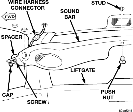
(3) Remove the four screws that secure each end of the sound bar to the rear roof rail reinforcements.
(4) Use a straight-bladed screw driver to unscrew the push nut that secures the center of the sound bar to the sound bar bracket stud.
(5) Lower the sound bar far enough to access and unplug the wire harness connector near the right end of the sound bar.
(6) Remove the sound bar from the vehicle. (7) Reverse the removal procedures to install. When installing the sound bar, push the push nut through the center sound bar mounting hole onto the mounting stud using finger pressure. Be certain that a spacer is in place on each of the four mounting screws between the sound bar and the rear roof rail reinforcements. Tighten the mounting screws to 1.7 N·m (15 in. lbs.).
ANTENNA
WARNING: ON VEHICLES EQUIPPED WITH AIR- BAGS, REFER TO GROUP 8M - PASSIVE RESTRAINT SYSTEMS BEFORE ATTEMPTING ANY STEERING WHEEL, STEERING COLUMN, OR INSTRUMENT PANEL COMPONENT DIAGNOSIS OR SERVICE. FAILURE TO TAKE THE PROPER PRE- CAUTIONS COULD RESULT IN ACCIDENTAL AIR- BAG DEPLOYMENT AND POSSIBLE PERSONAL INJURY.
(1) Disconnect and isolate the battery negative cable.
(2) Remove the right front fender inner liner. Refer to Front Fender in Group 23 - Body for the procedures.
(3) Unscrew the antenna mast from the antenna body (Fig. 17).
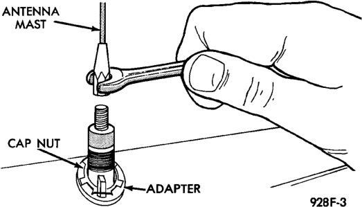
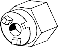
(4) Remove the antenna cap nut and adapter using an antenna nut wrench (Special Tool C-4816) (Fig. 18).
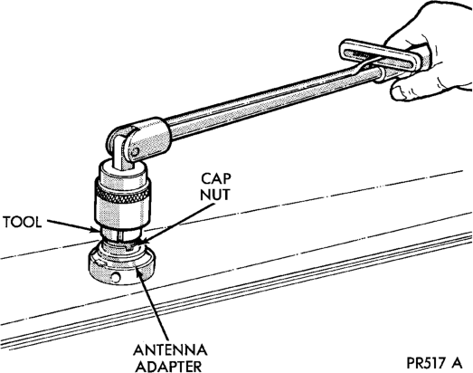
Install - Typical
(5) Lower the antenna body and cable assembly through the top of the fender far enough to access the antenna body by reaching up into the rear of the right front fender wheel housing (Fig. 19).
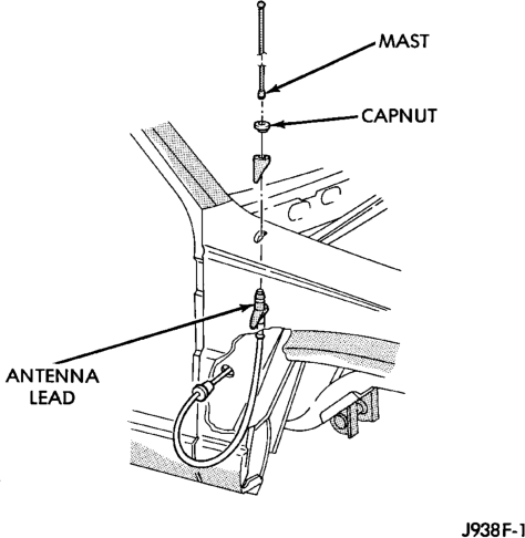
(6) Remove the fuse access panel by unsnapping it from the right cowl side trim panel.
(7) Remove the push nut that secures the right cowl side trim panel to the junction block stud (Fig. 20).
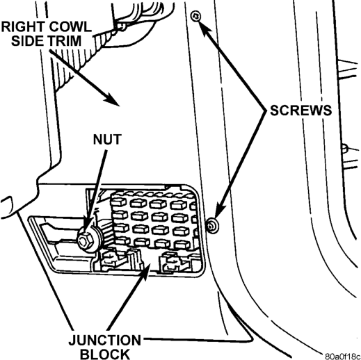
(8) Remove the two screws that secure the right cowl side trim panel to the right front door opening trim.
(9) Remove the right cowl side trim panel from the right cowl side inner panel.
(10) Reach under the right end of the instrument panel to unplug the coaxial cable connector near the junction block. Unplug the connector by pulling it apart while twisting the metal connector halves (Fig. 21). Do not pull on the cable.
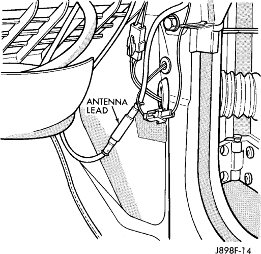
(11) Reach up into the rear of the right front fender wheel housing to disengage the coaxial cable grommet from the hole in the right cowl side outer panel.
(12) Pull the coaxial cable out through the right cowl side outer panel.
(13) Remove the antenna body and cable from the vehicle.
(14) Reverse the removal procedures to install. Tighten the antenna cap nut to 8 N·m (70 in. lbs.). Tighten the antenna mast to 3.3 N·m (30 in. lbs.).
SPECIAL TOOLS
ANTENNA