Wiring Diagrams — part 2 of 2 — 1996 Jeep Grand Cherokee ZJ Service Manual
← Contents 1 2
Pages 754–956 · 43 pages · 2 words repaired
8W-61 POWER DOOR LOCKS
DESCRIPTION AND OPERATION
INTRODUCTION
The Drivers Door Module (DDM) powers the drivers door lock motor. The Passengers Door Module (PDM) powers the passenger, both rear doorlock and the liftgate lock motors. The DDM and PDM each contain a door lock switch. When one of the switches is activated, a signal is sent on the CCD Bus to the other door module (PDM or DDM depending on which switch activated) to either LOCK or UNLOCK the lock motors. The Remote Keyless Entry transmitter can also LOCK or UNLOCK the door lock and liftgate lock motors. The PDM contains the radio frequency receiver that receives the RKE transmitter signals.
The vehicle is equipped with a Rolling Door Lock feature. When this feature is enabled, the PDM will lock the doors and liftgate after the vehicles reaches approximately 15 MPH.
POWER DOOR LOCKS
Circuit A250 from fuse 11 in the Power Distribution Center (PDC) powers circuit F81 through the circuit breaker in cavity 2 of the junction block. Circuit F81 supplies power to the Drivers Door Module (DDM) and the Passengers Door Module (PDM). The DDM and PDM operate the power door locks. Circuit Z1 provides ground for the power door locks.
The PDM contains the radio frequency receiver that receives the radio frequency signals from the Remote Keyless Entry (RKE) transmitter. After either the passenger door lock switch activates or it receives input from the RKE transmitter, the PDM sends the appropriate signal to the DDM over the CCD Bus. When the DRIVERS door lock switch activates, the DDM sends the appropriate signal to the PDM.
After receiving a LOCK signal, the DDM supplies battery voltage to the left front door lock motor on circuit P36. The DDM also connects circuit P34 from the motor to ground.
When the DDM receives the UNLOCK signal, it powers circuit P34 and grounds circuit P36.
After receiving a LOCK signal, the PDM supplies battery voltage to the right front door lock motor, rear door lock motors and liftgate lock motors on circuit P2. The PDM also connects circuit P34 from the motor to ground.
When the DDM receives the UNLOCK signal, it powers circuit P34 and grounds circuit P2.
REMOTE KEYLESS ENTRY
The Remote Keyless Entry (RKE) transmitter sends three unique signals to the radio frequency receiver in Passengers Door Module (PDM): LOCK, UNLOCK and PANIC. After it receives any one of the three signals, the PDM broadcasts the appropriate signal over the CCD bus.
LIFTGLASS
Circuit A250 from fuse 11 in the Power Distribution Center (PDC) powers circuit F70 through fuse 8 in the junction block. If the liftglass limit switch is closed, it connects circuit F70 to the liftglass switch (push button) on circuit P101. When closed, the liftglass switch connects circuit P101 to circuit P100. Circuit P100 feeds the liftglass solenoid. Circuit Z1 grounds the solenoid.
SCHEMATICS AND DIAGRAMS
WIRING DIAGRAM INDEX
The following index covers all components found in this section of the wiring diagrams. If the component you are looking for is not found here, refer to section 8W-02 for a complete list of all components shown in the wiring diagrams.
8W-62 POWER MIRRORS
DESCRIPTION AND OPERATION
INTRODUCTION
The Drivers Door Module (DDM) controls both power mirrors. The DDM adjusts the left mirror and signals the Passenger Door Module (PDM) over the CCD bus to adjust the right mirror. A push button switch on the outside of the DDM controls the horizontal and vertical position of both mirrors. The DDM also has a selector switch with right, left and center (off) positions for mirror selection.
Some models with Remote Keyless Entry (RKE) have a memory feature that allows the RKE transmitter to move the drivers seat and outside mirrors to a saved positions. The memory feature also can set the radio push buttons to preset stations.
POWER MIRROR
The circuits from the left outside mirror to the Driver Door Module (DDM) and right mirror to Passenger Door Module have identical circuit numbers. Each mirror has two motors; an UP/DOWN motor and a LEFT/RIGHT motor. The motors switch polarity to allow mirror adjustment. The DDM and PDM adjust mirror position by supplying power or ground to the mirror motors.
Each mirror has a vertical position sensor and a horizontal position sensor. The sensors in the left mirror connect to the DDM. Sensors in the right mirror connect to the PDM. The DDM and PDM determine horizontal position on circuit F85 and vertical position on circuit F84. Circuit F86 provides ground for each sensor.
If the vehicle is equipped with an automatic day/ night rear view mirror, the left power mirror also automatically adjusts to varying ambient light intensity. Circuits P114 and P112 connect the left power mirror to the automatic day/night rear view mirror.
LEFT MIRROR ADJUSTMENT
The DDM adjusts the position of the left mirror. When an UP adjustment is made, the DDM supplies power to the left mirror UP/DOWN motor on circuit F71 and grounds circuit F73.
When a DOWN adjustment is made, the polarity reveres. The DDM supplies power to circuit F73 and grounds circuit F71.
During LEFT adjustments, the DDM supplies power to the LEFT/RIGHT motor on circuit F75 and grounds circuit F73.
For RIGHT adjustments, the polarity reverses. The DDM supplies power to circuit F73 and grounds circuit F75.
RIGHT MIRROR ADJUSTMENT
The PDM adjusts the right mirror in response to signals it receives over the CCD bus from the DDM. When an UP adjustment is made, the PDM supplies power to the right mirror UP/DOWN motor on circuit F71 and grounds circuit F73.
When a DOWN adjustment is made, the polarity reveres. The PDM supplies power to circuit F73 and grounds circuit F71.
During LEFT adjustments, the PDM supplies power to the LEFT/RIGHT motor on circuit F75 and grounds circuit F73.
For RIGHT adjustments, the polarity reverses. The PDM supplies power to circuit F73 and grounds circuit F75.
HEATER ELEMENTS
The Driver Door Module (DDM) powers the heater circuit in the left power mirror. The Passenger Door Module powers the heater element in the right mirror. When the Body Control Module (BCM) detects the operator pressed the rear window defogger switch, it broadcasts the appropriate message to the DDM and PDM over the CCD bus. The DDM and PDM activate the heater elements in the mirrors until the BCM no longer broadcasts the message on the CCD bus.
The DDM and PDM power the heater element on circuit C16. On circuit Z1, the DDM and PDM provide ground for the heater elements.
SCHEMATICS AND DIAGRAMS
WIRING DIAGRAM INDEX
The following index covers all components found in this section of the wiring diagrams. If the component you are looking for is not found here, refer to section 8W-02 for a complete list of all components shown in the wiring diagrams.
8W-63 POWER SEAT
INDEX
DESCRIPTION AND OPERATION
HEATED SEATS . . . . . . . . . . . . . . . . . . . . . . . . . . 2 INTRODUCTION . . . . . . . . . . . . . . . . . . . . . . . . . 1 MEMORY SEATS . . . . . . . . . . . . . . . . . . . . . . . . . 2
DESCRIPTION AND OPERATION
INTRODUCTION
Both front power seats on this vehicle have separate motors for adjusting lumbar, front, rear, horizontal and vertical position. Also, the vehicle may have optional heated seats.
Some models with Remote Keyless Entry (RKE) have a memory feature that allows the RKE transmitter to move the drivers seat and outside mirrors to saved positions. The memory feature also can set the radio push buttons to preset stations.
POWER SEATS
Both power seat system are protected by a 20 amp circuit breaker located in cavity 3 of the junction block. Circuit A7 from fuse 15 in Power Distribution Center (PDC) powers circuit F35 through the circuit breaker.
In both power seats, circuit F35 feeds the seat position switch and lumbar adjustment switch. A BUS bar internal to the switches feeds all the contacts. Circuit Z1 provides ground for each power seat.
LUMBAR ADJUSTMENT
Lumbar position is adjustable on both power seats. Circuit F35 feeds the left and right lumbar adjustment switch. Identical circuits from each switch power or ground the lumbar motor to adjust lumbar position.
On either power seat, during LUMBAR FORWARD adjustments, the lumbar switch connects circuit F35 to circuit P106. Circuit P106 feeds the lumbar motor. The ground path is supplied on circuit P107 from the motor through the closed contacts in switch to circuit Z1.
For LUMBAR AFT adjustments, the circuits are reversed. Pl07 powers the motor and circuit P106 provides ground.
DRIVER’S SEAT
When the operator selects the HORIZONTAL FOR- WARD function, the switch passes power from circuit F35 to circuit P15. Circuit P15 connects to the motor.
page page
POWER SEATS . . . . . . . . . . . . . . . . . . . . . . . . . . 1 SCHEMATICS AND DIAGRAMS
WIRING DIAGRAM INDEX . . . . . . . . . . . . . . . . . . 3
Ground is provided on circuit P17 circuit back to the switch. A bus bar internal to the switch connects circuit P17 to ground on circuit Z1.
For HORIZONTAL REARWARD function the circuits are reversed. P17 is the feed, and P15 is the ground.
When the operator selects the REAR VERTICAL UP function, the switch passes power from circuit F35 to circuit P11. Circuit P11 connects to the motor. Ground is provided on circuit P13 back to the switch. A bus bar internal to the switch connects circuit P13 to ground on circuit Z1.
For REAR VERTICAL DOWN function the circuits are reversed. P13 is the feed, and P11 is the ground.
When the operator selects the FRONT VERTICAL UP function, the switch passes power from circuit F35 to circuit P19. Circuit P19 connects to the motor. Ground is provided on circuit P21 back to the switch. A bus bar internal to the switch connects circuit P21 to ground on circuit Z1.
For FRONT VERTICAL DOWN function the circuits are reversed. P21 is the feed, and P19 is the ground.
When the operator selects the RECLINE UP function, the switch passes power from circuit F35 to the P43 circuit. Circuit P43 connects to the motor. Ground is provided on circuit P41 back to the switch. A bus bar internal to the switch connects circuit P41 to ground on circuit Z1.
For RECLINE DOWN function the circuits are reversed. P41 is the feed, and P43 is the ground.
PASSENGER’S SEAT
When the operator selects the HORIZONTAL FOR- WARD function, the switch passes power from circuit F35 to circuit P14. Circuit P14 connects to the motor. Ground is provided on circuit P16 circuit back to the switch. A bus bar internal to the switch connects circuit P16 to ground on circuit Z1.
For HORIZONTAL REARWARD function the circuits are reversed. P16 is the feed, and P14 is the ground.
When the operator selects the REAR VERTICAL UP function, the switch passes power from circuit
F35 to circuit P10. Circuit P10 connects to the motor. Ground is provided on circuit P12 back to the switch. A bus bar internal to the switch connects circuit P12 to ground on circuit Z1.
For REAR VERTICAL DOWN function the circuits are reversed. P12 is the feed, and P10 is the ground.
When the operator selects the FRONT VERTICAL UP function, the switch passes power from circuit F35 to circuit P18. Circuit P18 connects to the motor. Ground is provided on circuit P20 back to the switch. A bus bar internal to the switch connects circuit P20 to ground on circuit Z1.
For FRONT VERTICAL DOWN function the circuits are reversed. P20 is the feed, and P18 is the ground.
When the operator selects the RECLINE UP function, the switch passes power from circuit F35 to the P44 circuit. Circuit P44 connects to the motor. Ground is provided on circuit P42 back to the switch. A bus bar internal to the switch connects circuit P42 to ground on circuit Z1.
For RECLINE DOWN function the circuits are reversed. P42 is the feed, and P44 is the ground.
MEMORY SEATS
Circuit A7 from fuse 15 in the Power Distribution Center (PDC) powers circuit F35 through the circuit breaker in cavity 3 of the junction block. Circuit F35 powers the Memory Seat Module (MSM). Circuit Z1 provides ground for the MSM.
When the operator moves the power seat switch or the lumbar adjustment switch, contacts in the switch CLOSE connecting the switch to the MSM. The MSM receives this input and operates the proper seat motor.
The drivers memory seat system can be activated by either one of the memory switches on the left door panel or through the Remote Keyless Entry (RKE) transmitter. If one of the memory switches on the door panel is pushed, the Drivers Door Module (DDM) signals the MSM on the CCD bus. If the memory function is activated by the RKE transmitter, the Passenger Door Module (PDM) signals the MSM on the CCD bus.
The following is a list of the circuits that connect from the power seat switch to the MSM and their functions:
• P40 - Recliner up • P48 - Recliner down • P19 - Front up • P21 - Front down • P11 - Rear up • P13 - Rear down • P15 - Seat forward • P17 - Seat rearward • P104 – lumbar rearward
• P105 – lumbar forward To operate the seat motor(s), the control module supplies the power and ground. The following is a list of the circuits that connect from the control module to the seat motors:
• P119, P121 - Seat front up and down • P111, P113 - Rear up and down • P115, P117 - Seat forward and rearward • P41, P43 - Recliner forward and rearward • P106, P107 – Lumbar forward and rearward
SEAT POSITION SENSORS
The Memory Seat Module (MSM) receives seat position inputs from five sensors in the driver’s seat. On circuit P29, the MSM supplies power to the seat position sensors on circuit P29. The MSM provides ground for the sensors on circuit P28.
Circuit P25 provides the input from the horizontal forward/rearward motor sensor to the MSM. Circuit P47 provides the input from the recline motor sensor. Circuit P103 sends the lumbar motor sensor input.
Circuit P27 provides the input from the rear riser motor sensor to the MSM. Circuit P26 provides the input from the front riser motor sensor. Circuit P29 from the MSM powers the riser motor sensors. The MSM provides ground for the riser motor sensors on circuit P28.
MEMORY SWITCH
The memory switch is used for programming the desired seat positions into the MSM memory. The memory switch also programs power mirror position into the Drivers Door Module (DDM) and the Passengers Door Module (PDM), and presets radio station selections.
Circuit P22 from DDM supplies power to the three sets of switches in the memory switch; set, memory 1, and memory 2. The three switch sets are wired in parallel and each contains a separate resistor. The voltage level present on circuit P22 depends on which memory switch is activated. Circuit Z1 from the DDM provides ground for the switches.
After a memory switch activates, the DDM broadcasts the appropriate signal on CCD bus. The MSM adjusts seat position in response to the signal.
Circuit M1 from the DDM powers the green Light Emitting Diodes (LED) in the set switch. Circuit G49 powers the red LED in the set switch. Circuit Z1 provides ground for the LEDs.
HEATED SEATS
Separate control modules operate the driver and passenger heated seats. Circuit F35 from the circuit breaker in cavity 3 of the junction block supplies power to both heated seat control modules. Circuit A7 from fuse 15 in the Power Distribution Center (PDC) powers circuit F35 through the circuit breaker.
When the ignition switch is in the RUN position, it connects circuit A1 from fuse 8 in the PDC to circuit A22. Circuit A22 powers circuit F71 through fuse 12 in the junction block. Circuit F71 splices to supply power to the driver and passenger heated seat switches and provides an input to the heated seat control modules. Circuit Z1 provides ground for the control modules and both heated seat switches.
Both heated seat switches have three positions; OFF, LOW or HIGH. Circuit P7 sends the drivers’s heated seat switch signal to the drivers heated seat control module. Circuit P8 sends the passenger heated seat switch signal to the passenger heated seat control module. In the LOW and HIGH positions, the drivers heated seat switch connects battery voltage on circuit F71 to circuit P7 (driver’s) or P8 (passenger). The LOW and HIGH position detentes have a resistor in series between the detente and circuit P7 or P8. Internal to the switch, voltage from circuit F71 passes through the resistor to circuit P7 or P8. The voltage level on circuit P7 or P8 from the switch depends on switch position (LOW or HIGH).
After receiving a signal from its heated seat switch, the heated seat control modules powers the heater grids in the seat. From either control module, circuit P87 powers the grid in the drivers seat cushion Current flows out of the seat cushion on circuit P88 to the grid on the seat back. Circuit Z1 from the grid in the seat back supplies ground.
Each heated seat control module monitors seat temperature through a thermistor in each seat. When seat temperature reaches the temperature selected by the operator through the heated seat switch, the control module stops supplying voltage to the heated seat grids. To maintain selected seat temperature, the control module cycles the grid ON and OFF.
SCHEMATICS AND DIAGRAMS
WIRING DIAGRAM INDEX
The following index covers all components found in this section of the wiring diagrams. If the component you are looking for is not found here, refer to section 8W-02 for a complete list of all components shown in the wiring diagrams.
8W-64 POWER SUNROOF
INDEX
DESCRIPTION AND OPERATION
POWER SUNROOF . . . . . . . . . . . . . . . . . . . . . . . 1
DESCRIPTION AND OPERATION
POWER SUNROOF
When the ignition switch is in the ACCESSORY or RUN position it connects circuit A1 from fuse 8 in the Power Distribution Center (PDC) to circuit A31. Circuit A31 powers circuit F86 through the circuit breaker in cavity 1 of the junction block. Circuit F86 feeds the power sunroof control module and switch. Circuit Z1 provides ground for the sunroof system.
When the operator selects the OPEN function, voltage is provided on circuit F86 through the closed contacts in the switch to circuit Q41. Circuit Q41 connects between the switch and the control module.
The control module then activates the motor and moves the sunroof to the desired position. A position sensor is used to prevent the sunroof from being moved to far in any one direction. When the sensor detects the roof is at the end of its travel it sends a signal to the control module and voltage is shut off to the motor.
page page
SCHEMATICS AND DIAGRAMS
WIRING DIAGRAM INDEX . . . . . . . . . . . . . . . . . . 1
When the operator selects the CLOSE function, voltage is provided on circuit F86 through the closed contacts in the switch to circuit Q42. Circuit Q42 connects between the switch and the control module.
The control module then activates the motor and moves the sunroof to the desired position. The position sensor detects when the roof is at the end of its travel it sends a signal to the control module and voltage is shut off to the motor.
SCHEMATICS AND DIAGRAMS
WIRING DIAGRAM INDEX
The following index covers all components found in this section of the wiring diagrams. If the component you are looking for is not found here, refer to section 8W-02 for a complete list of all components shown in the wiring diagrams.
8W-65 SPEED PROPORTIONAL STEERING
INDEX
DESCRIPTION AND OPERATION
DATA LINK CONNECTOR . . . . . . . . . . . . . . . . . . . 1 INTRODUCTION . . . . . . . . . . . . . . . . . . . . . . . . . 1 SPEED PROPORTIONAL STEERING CONTROL
MODULE . . . . . . . . . . . . . . . . . . . . . . . . . . . . . . 1
DESCRIPTION AND OPERATION
INTRODUCTION
The speed proportioning steering system automatically adjusts steering effort based on vehicle speed. The system provides additional steering assist while the vehicle is stationary or at low driving speeds. At slower speeds, the system provides greater assist. At higher speeds, it provides less assist resulting in increased steering effort.
In the RUN position, the ignition switch connects circuit A1 from fuse 8 in the Power Distribution Center (PDC) to circuit A22. Circuit A22 powers circuit F83 through fuse 6 in the junction block. Circuit F83 supplies power to the Speed Proportional Steering Control Module (SPSCM). Circuit Z2 provides ground for the SPSCM.
SPEED PROPORTIONAL STEERING CONTROL MODULE
Circuit F83 powers the Speed Proportional Steering Control Module (SPSCM). Circuit Z2 provides ground for the SPSCM.
On circuit S1, the SPSCM supplies 5 volts to the steering wheel speed sensor. The sensor provides two signals to the SPSCM on circuits S3, and S4. The SPSCM provides ground for the steering wheel speed sensor on circuit S2.
page page
SPEED PROPORTIONAL STEERING
SOLENOID . . . . . . . . . . . . . . . . . . . . . . . . . . . . 1 SCHEMATICS AND DIAGRAMS
WIRING DIAGRAM INDEX . . . . . . . . . . . . . . . . . . 1
Circuit G7 supplies the vehicle speed sensor to the SPSCM.
SPEED PROPORTIONAL STEERING SOLENOID
The speed proportional steering control module (SPSCM) operates the speed proportional steering solenoid. The SPSCM supplies a pulse width modulated voltage to the solenoid. Circuits S99 and S98 connect the SPSCM to the solenoid.
DATA LINK CONNECTOR
Circuits D98 and D99 connect the Speed Proportional Steering Control Module (SPSCM) to the data link connector. Circuit D99 connects to circuit D83 which continues to the data link connector. The SPSCM transmits data to the scan tool through the data link connector on circuit D99. The SPSCM receives data from the scan tool on circuit D98.
SCHEMATICS AND DIAGRAMS
WIRING DIAGRAM INDEX
The following index covers all components found in this section of the wiring diagrams. If the component you are looking for is not found here, refer to section 8W-02 for a complete list of all components shown in the wiring diagrams.
8W-70 SPLICE INFORMATION
DESCRIPTION AND OPERATION
INTRODUCTION
This section identifies all splices in the wiring diagrams. It also shows the splices in their entirety. All circuits that are part of the splices are shown, and the systems they affect are referenced. For viewing the location of each splice in the vehicle, refer to Section 8W-95.
8W-80 CONNECTOR PIN-OUTS
DESCRIPTION AND OPERATION
INTRODUCTION
The pages referenced in this section show the connector, the circuits in the connector, and the pin that circuit occupies. Individual connector numbers are referenced on diagram pages throughout Group 8W.
8W-90 CONNECTOR LOCATIONS
DESCRIPTION AND OPERATION
INTRODUCTION
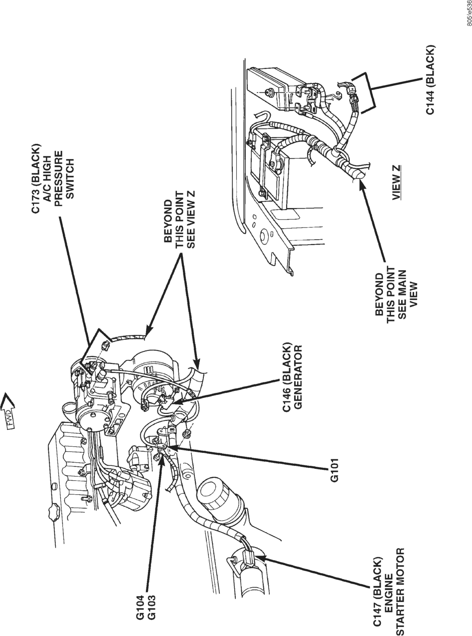
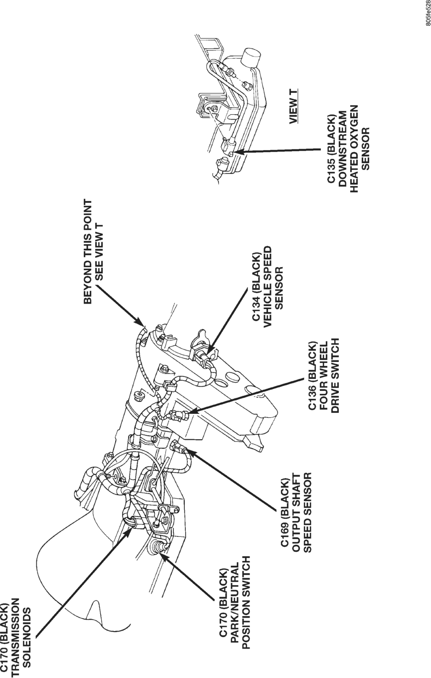
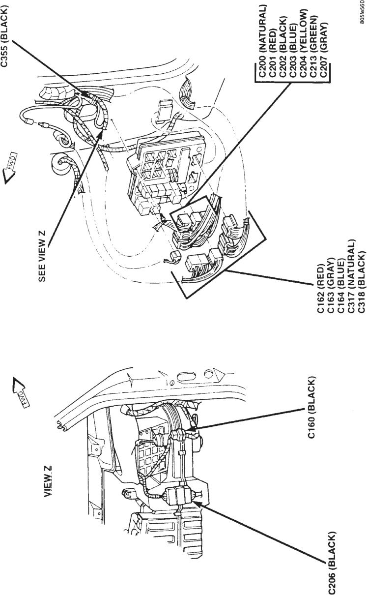
This section provides illustrations identifying component and connector locations in the vehicle. A connector index is provided. Use the wiring diagrams in each section for connector number identification. Refer to the index for the proper figure number.
Conn # Color Location Fig.
C100 BK Rear of Right Fog Lamp
1
C101 BK On Power Steering Pump
3, 5
C102 BK Rear of Left Fog Lamp 1
C103 BK Rear of Left Headlamp 1, 5
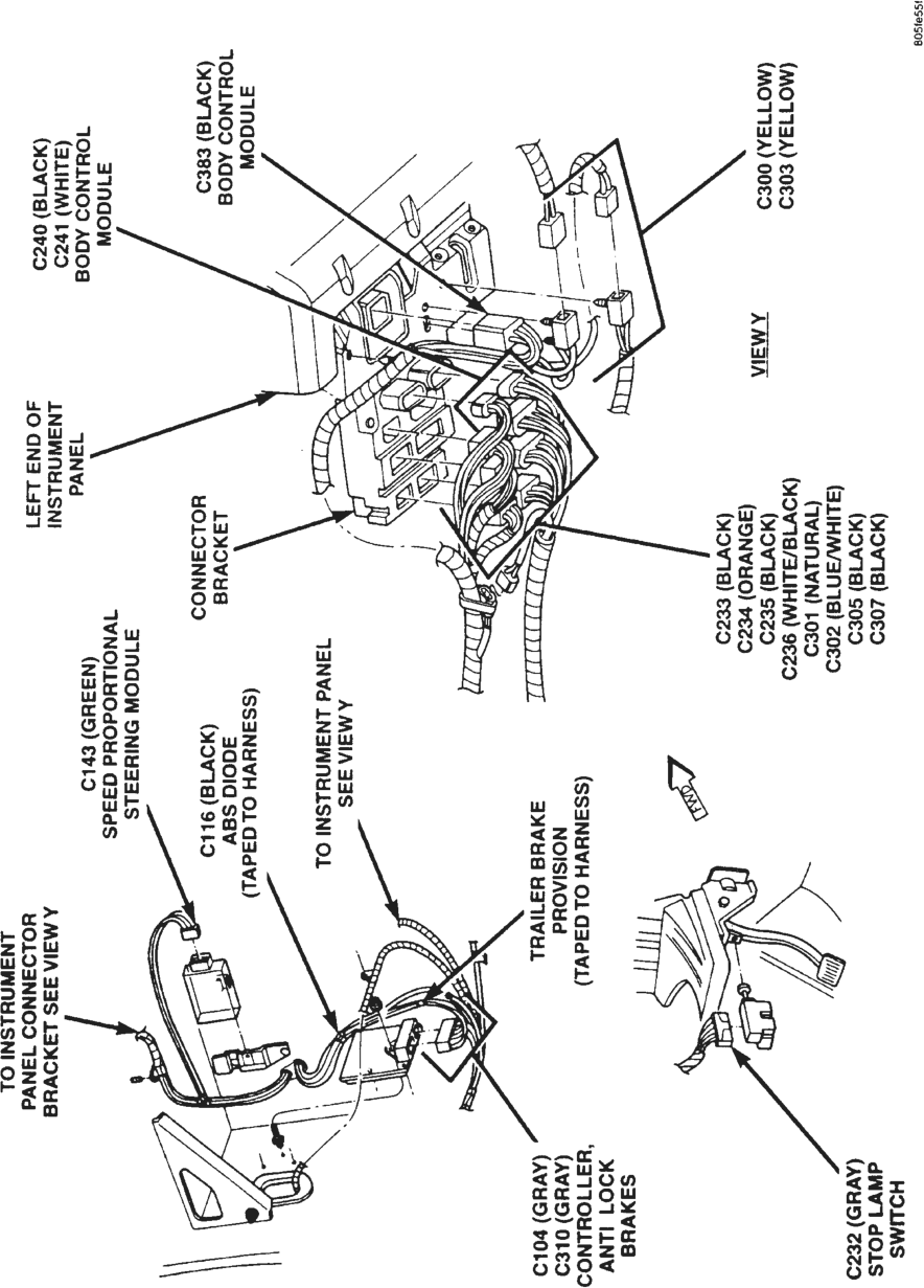
C104 GY Lower Left of Instrument Panel
13
C105 BK Front of Left Fender Side Shield
3
C106 BK Left Fender Side Shield, Near Brake Master Cylinder
3
C107 BK Left Fender Side Shield, Near Brake Master Cylinder
3
C108 BK Left Fender Side Shield, Near Brake Master Cylinder
3
C109 BK Left Rear Corner of Engine Compartment
3
C110 BK Bottom of Windshield Washer Fluid Reservoir
4
C111 BK Bottom of Windshield Washer Fluid Reservoir
4
C112 BK Center of Cowl 4
C113 BK Bottom of Windshield Washer Fluid Reservoir
4
C114 BK Below Battery Tray 4
C115 BK Right Fender Side Shield, Below PDC
2
C116 BK Lower Left of Instrument Panel
13
C119 GY Left Side of Oil Pan (4.0L Engine)
5
SCHEMATICS AND DIAGRAMS
CONNECTOR/GROUND LOCATIONS
For items that are not shown in this section a N/S is placed in the Fig. column.
Conn # Color Location Fig.
C119 GY Right Front of Transmission
10
C120 BK On Thermostat Housing 5
C121 GY Injector No. 1 5, 9
C122 GY Injector No. 2 5, 8
C123 GY Injector No. 3 5, 9
C124 GY Injector No. 4 5, 8
C125 BK On Throttle Body 5, 9
C126 BK On Throttle Body 5, 9
C127 GY On Intake Manifold 5, 8
C128 BK On Throttle Body 5
C129 GY Injector No. 5 5, 9
C130 GY Injector No. 6 5, 8
C131 BK Right Rear Corner of Engine Compartment, Near PCM
2
C132 GY Right Rear Corner of Engine Compartment, Near PCM
2
C133 BK Left Fog Lamp 1
C134 BK Rear of Transfer Case 7, 10
C135 BK Above Rear of Catalytic Convertor
7, 10
C136 BK Left Front of Transfer Case
7, 10
C137 BK Right Rear of Engine (4.0L Engine)
5
C137 BK Rear of Engine (5.2L Engine)
9
C138 BK Near Distributor 5, 9
C139 BK Near Distributor 5, 9
Conn # Color Location Fig.
2
C140 BK Right Rear Corner of Engine Compartment, At PCM
2
C141 WT Right Rear Corner of Engine Compartment, At PCM
2
C142 GY Right Rear Corner of Engine Compartment, At PCM
13
C143 GN Top Left Corner of Dash Panel, Behind Instrument Panel
C144 BK Below PDC 6
C145 BK Right Front of Engine 5, 8
C146 BK At Generator 6
C147 BK At Starter Motor 6, 8
C148 BK Lower Left Front of Engine Compartment
1
C149 BK Right Fog Lamp 1
C150 BK Rear of Right Fog Lamp
1
C151 BK Lower Right Front of Engine Compartment
1
C152 BK At Horn, Lower Right Front of Vehicle
1
C153 BK At Horn, Lower Right Front of Vehicle
1
C154 BK Right Fender Side Shield
2
C155 BK Right Rear Corner of Engine Compartment
2
C156 BK Right Fender Side Shield
2
C157 BK Right Rear Corner of Engine Compartment
2
C158 BK Right Rear Corner of Engine Compartment
2
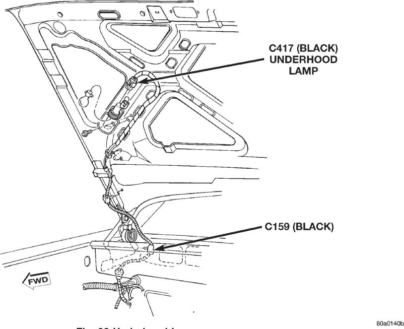
C159 BK Right Rear Corner of Engine Compartment
2, 22
C160 BK Right Corner of Instrument Panel
12
C161 BK Front of Left Fender Side Shield
3
C162 RD Behind Right Kick Panel, At Junction Block
12
Conn # Color Location Fig.
12
C163 GY Behind Right Kick Panel, At Junction Block
12
C164 BL Behind Right Kick Panel, At Junction Block
C169 BK Left Side of Transmission
7, 10
C170 BK Left Side of Transmission
7, 10
C171 BK Left Side of Transmission
7, 10
C172 BK Rear of Generator 8
C173 BK Near A/C Compressor 6, 8
C175 GY Injector No. 7 9
C176 GY Injector No. 8 8
C179 BK On Radiator Center Support
1
C181 BK On Throttle Body 9
C200 NAT Behind Right Kick Panel, At Junction Block
12
C201 RD Behind Right Kick Panel, At Junction Block
12
C202 BK Behind Right Kick Panel, At Junction Block
12
C203 BL Behind Right Kick Panel, At Junction Block
12
C204 YL Behind Right Kick Panel, At Junction Block
12
C205 BK Right Courtesy Lamp 11
C206 BK On Front of HVAC Unit 12
C207 GY Behind Right Kick Panel, At Junction Block
12
C208 BK At Glove Box Lamp 11
C209 BK On HVAC Unit N/S
C210 BK Rear of Switch N/S
C211 BK Rear of Vehicle Information Center (VIC)
11
C212 RD Center of Instrument Panel
11
Conn # Color Location Fig.
12
C213 GN Behind Right Kick Panel, At Junction Block
C214 BK Rear of Ash Receiver Lamp
11
C215 BK On Bottom of HVAC Unit
N/S
C216 BK Rear of Cigar Lighter 11
C217 BK Behind Rear Wiper Switch
11
C218 BK Rear of Overdrive Switch
11
C219 GY Rear of Radio 11
C220 BK Rear of Radio 11
C221 BK Rear of Radio 11
C222 BK Rear of Instrument Cluster
11
C223 BK Rear of Headlamp Switch
11
C224 YL Behind Passenger Airbag
11
C225 BK On Steering Column 14
C226 GY On Steering Column, Near Ignition Switch
14
C227 BK Left Courtesy Lamp 11
C228 BK On Steering Column 14
C230 NAT On Steering Column 14
C231 WT Right End Of Instrument Panel
N/S
C232 GY Top of Brake Pedal Arm 13
C233 BK Lower Left of Instrument Panel, In Connector Bracket
13
C234 OR Lower Left of Instrument Panel, In Connector Bracket
13
C235 BK Lower Left of Instrument Panel, In Connector Bracket
13
C236 WT Lower Left of Instrument Panel, In Connector Bracket
13
C237 BK Steering Column, On Shift Cable
N/S
C238 BK Top Right of Instrument Panel
11
C239 BK At Junction Block N/S
Conn # Color Location Fig.
C240 BK Lower Left of Instrument Panel
13
C241 WT Lower Left of Instrument Panel
13
11
C242 GY Top of Instrument Panel, Between Steering Column and Center Floor Console
C243 BK Rear of Left Instrument Panel Speaker
11
C244 BK Rear of Power Outlet 11
C245 BK Center, Top of Instrument Panel
11
C246 BL Left Side of HVAC Housing
N/S
C247 RD Above Glove Box 11
C248 BK On Steering Column N/S
C249 BK Lower Left of Instrument Panel
11
C250 NAT Right Side of HVAC N/S
C251 BK Right Side of HVAC N/S
C252 BK Left Side of HVAC N/S
C253 YL Top of HVAC N/S
C254 BK Right Side of HVAC N/S
C256 BK On HVAC N/S
C300 YL Lower Left of Instrument Panel
13
C301 NAT Lower Left of Instrument Panel, In Connector Bracket
13
C302 BL/ WT
Lower Left of Instrument Panel, In Connector Bracket
13
C303 YL Lower Left of Instrument Panel
13, 14
C304 GY Lower Left of Instrument Panel
N/S
C305 BK Lower Left of Instrument Panel, In Connector Bracket
13
C306 BK Near Bottom of Driver’s Seat Belt Clasp
16
C307 BK Lower Left of Instrument Panel, In Connector Bracket
13
C308 BK Below Center Floor Console, Near Park Brake
16
Conn # Color Location Fig.
C309 GY In Left Rear Door 19
13
C310 GY Top Left Corner of Dash Panel, Behind Instrument Panel
C311 BK Below Right Rear Passenger Seat
16
16
C312 YL Below Center Floor Console, Near Park Brake
C313 RD Below Right Rear Passenger Seat
16
C314 BK Below Right Rear Passenger Seat
16
C315 BK Near Fuel Tank 16
C316 BK Left Rear Quarter Panel, Near Bottom of Liftgate Opening
17
C317 NAT Behind Right Kick Panel, At Junction Block
12
C318 BK Behind Right Kick Panel, At Junction Block
12
C319 BK Left Rear Quarter Panel N/S
C320 GY Right Rear Quarter Panel, Near Liftgate Opening
16
C321 BK In Liftgate 21
C322 GN In Liftgate 21
C323 GY In Liftgate 21
C324 BK In Liftgate 21
C325 GN In Liftgate 21
C326 GY In Liftgate 21
C327 BK Rear of Cargo Lamp 17
C328 GY Left Rear Quarter Panel, Near Bottom of Liftgate Opening
17
C329 BK Below Left Rear Passenger Seat
17
C330 GY In Right Rear Door 19
C331 BK Left Rear Quarter Panel 20
C332 WT Below Right Rear Passenger Seat
16
C333 WT Below Right Rear Passenger Seat
16
C334 BK In Left Front Door 18
Conn # Color Location Fig.
C335 BK Rear of Right Front Seat
16
C336 BK Top of Right A-Pillar 15
C337 BK Behind Rear View Mirror
15
C338 BK Top of Left A-Pillar 15
C339 RD Center of Headliner, Above Rear View Mirror
15
C340 WT In Left Front Door 18
C341 NAT Behind Dome Lamp 15
C342 BK In Right Front Door 18
C343 BK In Left 9B9 Pillar 19
C344 BK In Right Front Door 18
C345 BK In Right 9B9 Pillar 19
C346 BK In Left Front Door 18
C347 BK In Right Front Door 18
C348 BK In Right Front Door 18
C349 BK Left Rear Quarter Panel 20
C350 BK Left Rear Quarter Panel 20
C351 GY In Right Front Door 18
C352 BK In Left Front Door 18
C353 BK In Left Front Door 18
C354 BK In Left Front Door 18
C355 BK Behind Right Kick Panel, At Junction Block
12
C356 BK In Right Front Door 18
C357 BK In Left Front Door 18
C358 BK In Left Front Door 18
C359 BK In Liftgate 21
C360 BK In Liftgate 21
C361 NAT In Liftgate 21
C362 BK In Liftgate 21
C363 BK In Liftgate 21
C364 BK In Liftgate 21
C365 BK In Liftgate 21
C366 BK In Liftgate 21
C367 BK In Liftgate 21
C368 BK In Liftgate 21
C369 BK On Trailer Hitch 20
C370 NAT Center of Headliner, Above Rear View Mirror
15
C371 BK Near Top of Right B-Pillar
15
Conn # Color Location Fig.
C372 BK Left Rear Quarter Panel 20
C373 BK Left Rear Quarter Panel 20
C374 BK In Right Rear Door 19
C375 BK In Right Rear Door 19
C376 BL In Right Rear Door 19
C377 BK In Right Rear Door 19
C378 BK In Left Rear Door 19
C379 BK In Left Rear Door 19
C380 BL In Left Rear Door 19
C381 BK In Left Rear Door 19
C382 WT In Right Front Door 18
C383 BK Lower Left of Instrument Panel
13
C384 BK Left Rear Quarter Panel 20
C385 BK Left Side of Center Floor Console
16
C386 BK In Driver’s Door N/S
C387 BK In Driver’s Door N/S
C388 BK In Driver’s Door N/S
C400 NAT At Lamp N/S
C401 BK At Lamp N/S
C402 BK At Lamp N/S
C403 BK At Lamp N/S
C405 NAT At Lamp N/S
C406 BK At Lamp N/S
C407 BK At Lamp N/S
C408 BK At Lamp N/S
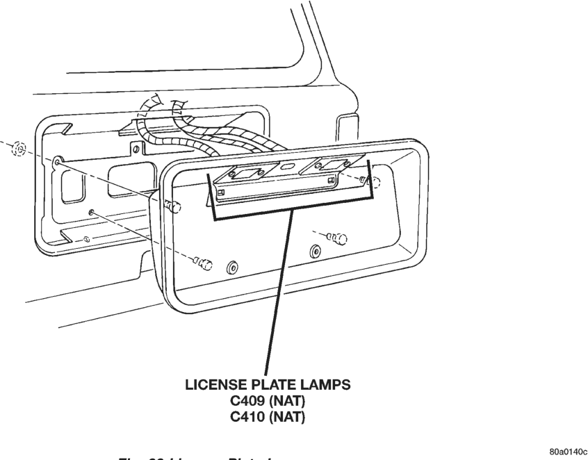
C409 NAT In Liftgate, Behind License Plate Lamps
23
C410 NAT In Liftgate, Behind License Plate Lamps
23
C412 GN On Passenger’s Front Seat
N/S
C413 BK Under Passenger’s Front Seat
N/S
C417 BK On Underside of Hood 22
C424 WT At Lamp N/S
C425 GY At Lamp N/S
C426 BK At Lamp N/S
C427 WT At Lamp N/S
C428 GY At Lamp N/S
C429 BK At Lamp N/S
C431 BK At Lamp N/S
C432 BK At Lamp N/S
Conn # Color Location Fig.
C433 BK At Lamp N/S
C434 BK Rear of Sunroof N/S
C435 RD Under Passenger’s Seat
N/S
C436 RD Under Passenger’s Seat
N/S
C437 BK Under Passenger’s Seat
N/S
C438 WT Under Passenger’s Seat
N/S
C439 GY Under Passenger’s Seat
N/S
C440 GN Under Passenger’s Seat
N/S
C441 BK Under Passenger’s Seat
N/S
C442 BK Under Passenger’s Seat
N/S
C443 BK In Driver’s Seat N/S
C444 BK Under Driver’s Seat N/S
C445 BK Under Driver’s Seat N/S
C446 BK At Driver’s Seat N/S
C447 OR At Driver’s Seat N/S
C448 RD Under Driver’s Seat N/S
C449 BK Under Driver’s Seat N/S
C450 RD Under Driver’s Seat N/S
C451 BK Under Driver’s Seat N/S
C452 BK Under Driver’s Seat N/S
C453 GN Under Driver’s Seat N/S
C454 BK Under Driver’s Seat N/S
C455 BK In Driver’s Seat N/S
C456 BK In Driver’s Seat N/S
C457 BK Under Driver’s Seat N/S
C458 BK In Driver’s Seat N/S
C459 BK Under Driver’s Seat N/S
G100 Right Fender Side Shield
2
G101 Right Side of Engine Block (4.0L Engine)
6
G101 Below Generator (5.2L Engine)
8
Conn # Color Location Fig.
G103 Right Side of Engine Block (4.0L Engine)
6
G103 Below Generator (5.2L Engine)
8
G104 Right Side of Engine Block (4.0L Engine)
8
G104 Below Generator (5.2L Engine)
8
G105 Right Rear of Engine (4.0L Engine)
5
G105 Below A/C Compressor (5.2L Engine)
9
G106 Right Fender Side Shield
2
G107 Right Fender Side Shield
2
Conn # Color Location Fig.
G108 Front of Left Fender Side Shield
3
G109 Front of Left Fender Side Shield
3
G300 Right Rear Quarter Panel
16
G301 Rear of Passenger’s Seat
16
G302 On Floor Pan, Rear of Driver’s Seat
17
G303 On Floor Pan, Rear of Driver’s Seat
17
G304 On Floor Pan, Rear of Driver’s Seat
17
G305 On Floor Pan, Rear of Driver’s Seat
17
8W-95 SPLICE LOCATIONS
DIAGNOSIS AND TESTING
INTRODUCTION
This section provides illustrations identifying the general location of the splices in this vehicle. A splice index is provided. Use the wiring diagrams in each section for splice number identification. Refer to the index for proper splice number.
Splice Number
Location Fig.
S100 Near Power Distribution Center 1
S101 Near Battery Temperature Sensor T/O
1
S102 Near Battery Temperature Sensor T/O
1
S103 Near Battery Temperature Sensor T/O
1
S104 Right Front Corner of Engine Compartment
1
S105 Right Front Corner of Engine Compartment
1
S106 Right Front Corner of Engine Compartment
1
S107 Left Front Corner of Engine Compartment
1
S108 Left Front Corner of Engine Compartment
1
S109 Near EVAP/Purge Solenoid T/O 1
S116 Near Branch to Brake Warning Switch
1
S117 In Branch to Brake Warning Switch
1
S118 In Branch to Brake Warning Switch
1
S119 Left Rear of Engine Compartment
1
S120 Near T/O to Low Washer Fluid Level Sensor
1
S121 Near T/O to Low Washer Fluid Level Sensor
1
S122 Near Vehicle Speed Control Servo T/O
1
S123 Near Vehicle Speed Control Servo T/O
1
SCHEMATICS AND DIAGRAMS
SPLICE LOCATIONS
For splices that are not shown in the figures in this section a N/S is placed in the Fig. column
Splice Number
Location Fig.
S124 Near Vehicle Speed Control Servo T/O
1
S125 Near Controller, Antilock Brakes 5
S126 Near A/C High Pressure Switch T/O (4.0L Engine)
1
S126 In Branch to Starter Motor (5.2L Engine)
3
S127 Near Injector No. 3 T/O (4.0L Engine)
2
S128 Near Injector No. 5 T/O (4.0L Engine)
2
S128 Near T/Os for Injectors 6 and 8 (5.2L Engine)
3
S129 Rear of Engine (4.0L Engine) 2
S129 Near Injector No. 3 T/O (5.2L Engine)
3
S130 Rear of Engine (4.0L Engine) 2
S130 Near Crankshaft Position Sensor T/O (5.2L Engine)
3
S131 In Branch to Transmission (4.0L Engine)
2
S131 Right Rear of Engine (5.2L Engine)
3
S132 Near Branch to Transmission (4.0L Engine)
2
S132 Rear of Engine (5.2L Engine) 3
S133 In Branch to Oil Pressure Sensor and Crankshaft Position Sensor (4.0L Engine)
2
S133 Near Injector No. 5 T/O (5.2L Engine)
3
S134 Near Branch to Powertrain Control Module (4.0L Engine)
2
S134 Rear of Engine (5.2L Engine) 3
Splice Number
Location Fig.
S135 Near Branch to PCM (4.0L Engine)
2
S135 Right Rear of Engine (5.2L Engine)
3
S136 Near Injector No. 7 T/O (5.2L Engine)
3
S200 Near Headlamp Switch T/O 4
S201 Near Headlamp Switch T/O 4
S202 Near Stop Lamp Switch T/O 4
S203 Near Stop Lamp Switch T/O 4
S204 Near Branch to Instrument Cluster
4
S205 Near Branch to Instrument Cluster
4
S206 Near Branch to Rear Window Defogger Switch
4
S207 Near Shift Interlock T/O 4
S208 Near Branch to Shift Interlock T/O
4
S209 Near Branch to Shift Interlock T/O
4
S210 Near Transfer Case Illumination Lamp T/O
4
S211 Near Branch to Graphic Display Module/Vehicle Information Center
4
S212 Near Passenger Airbag T/O 4
S214 Near Passenger Airbag T/O 4
S215 Near Passenger Airbag T/O 4
S216 Near Passenger Airbag T/O 4
S218 Near Passenger Airbag T/O 4
S219 Near Branch to Graphic Display Module/Vehicle Information Center
4
S220 Near Passenger Airbag T/O 4
S221 On HVAC Harness 6
S222 On HVAC Harness 6
S223 On HVAC Harness 6
S224 On HVAC Harness 6
S225 On HVAC Harness 6
S226 On HVAC Harness 6
S300 Near Left Kick Panel 5
S301 Near Left Kick Panel 5
S302 Near Left Kick Panel 5
Splice Number
Location Fig.
S303 Near Branch to Floor Console 7
S304 Near Branch to Floor Console 7
S305 Near Branch to Left Rear Door 7
S306 Near Branch to Left Rear Door 7
S307 Near Branch to Left Rear Door 7
S308 Near Branch to Power Amplifier 7
S309 In Branch to Power Amplifier 7
S310 Near Branch to Power Amplifier 7
S311 Left Rear Quarter Panel 7
S312 Left Rear Quarter Panel 7
S313 Left Rear Quarter Panel 7
S314 Top of Left Rear Quarter Panel 7
S315 Top of Left Rear Quarter Panel 7
S316 Near Right Side T/O for Liftgate 8
S317 In Branch to Power Amplifier 7
S318 In Branch to Power Amplifier 7
S319 Near Branch to Right Rear Door Ajar Switch
8
S320 In Branch to Dome/Reading Lamp
9
S321 Between Day/Night Mirror T/O and Right Vanity Mirror T/O
9
S322 Between Day/Night Mirror T/O and Right Vanity Mirror T/O
9
S323 Near Day/Night Mirror T/O 9
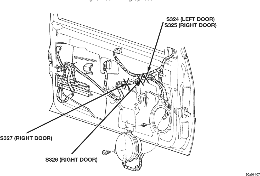
S324 In Left Front Door, Between Power Window Motor T/O and Power Mirror T/O
10
S325 In Right Front Door, Near Power Window Motor T/O
10
S326 In Right Front Door, Near Power Window Motor T/O
10
S327 In Right Front Door, Near Power Window Motor T/O
10
S328 In Liftgate, Near Rear Window Defogger T/O
11
S329 In Liftgate, Near Rear Wiper Motor T/O
11
S330 In Factory Trailer Tow Harness, Near Body Harness Connector
7
S331 In Factory Trailer Tow Harness, Near Trailer Receptacle Harness Connector
7
S332 In Liftgate, Near Left Body Connectors
11
Splice Number
Location Fig.
S333 Near T/O to Right Power Seat 8
S334 In Branch to Dome Reading Lamp
9
S335 In Branch to Power Amplifier 7
11
S336 In Liftgate, Between Rear Wiper Motor T/O and Liftgate Lock Motor T/O
S400 In Left Power Seat Harness, Near Lumbar Motor T/O
N/S
S401 In Left Power Seat Harness, Near Riser Motor Sensor T/O
N/S
S402 In Left Power Seat Harness, Between Riser Motor Sensor T/O and Heated Seat Module T/O
N/S
S403 In Left Power Seat Harness, Near Seat Switch T/O
N/S
S404 In Right Power Seat Harness, Near Seat Motor T/Os
N/S
S405 In Right Power Seat Harness, Near Seat Motor T/Os
N/S
S406 In Right Power Seat Harness, In Branch to Seat Switch
N/S
S407 In Left Power Seat Harness, Near Lumbar Motor T/O
N/S
S408 Near Left Front Turn Signal Bulb Socket
N/S
Splice Number
Location Fig.
S409 Near Left Front Turn Signal Bulb Socket
N/S
S410 Near Left Front Park Lamp Bulb Socket
N/S
N/S
S411 In Left Tail Lamp Harness, Between Body Connector and Grommet
N/S
S412 In Left Tail Lamp Harness, Between Body Connector and Grommet
S413 Near Right Front Turn Signal Bulb Socket
N/S
S414 Near Right Front Turn Signal Bulb Socket
N/S
S415 Near Right Front Park Lamp Bulb Socket
N/S
S416 In Right Tail Lamp Harness, Between Body Connector and Grommet
N/S
S417 In Right Tail Lamp Harness, Between Body Connector and Grommet
N/S
S418 In License Plate Lamp Harness 11
S419 In License Plate Lamp Harness 11 .
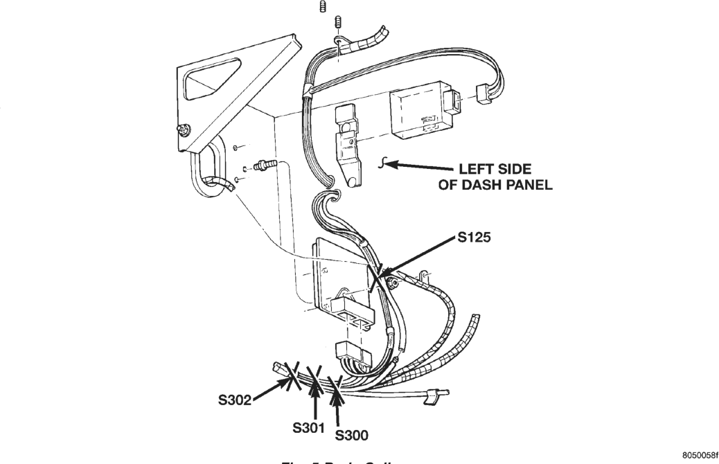
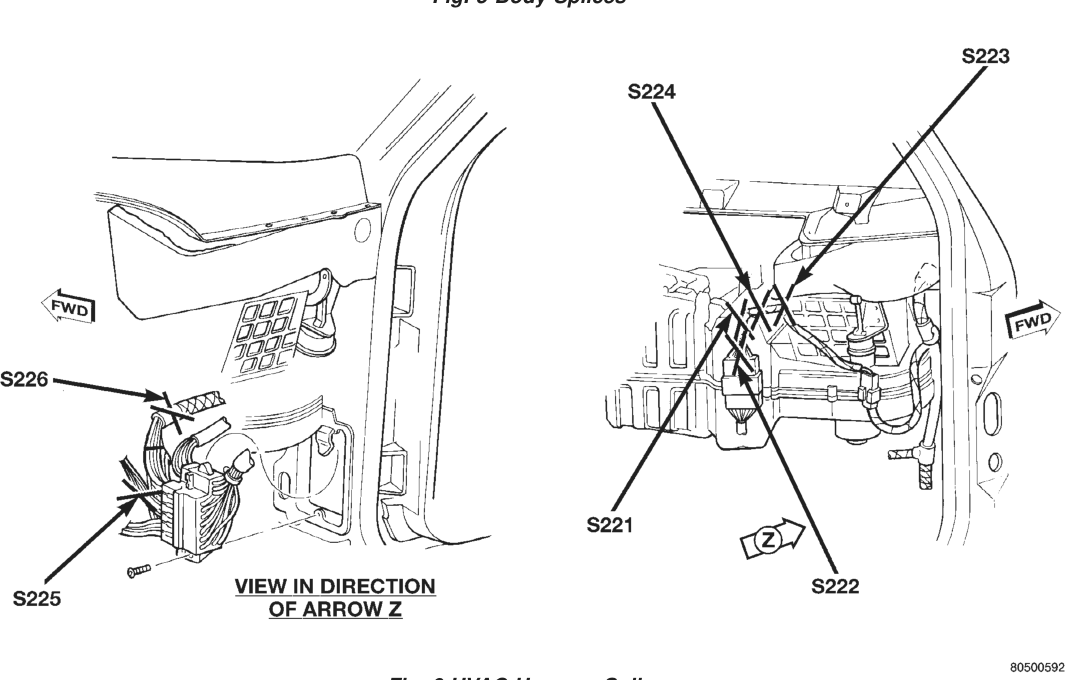
Fig. 9 Roof Wiring Splices