Wiper and Washer Systems — 1996 Jeep Grand Cherokee ZJ Service Manual
Pages 388–400 · 13 pages · 10 words repaired
• Continuous fixed-cycle wipe. • A park mode that operates the wiper motor until the blade reaches its park position when the rear wiper switch or ignition switch is placed in the Off position, or when the liftgate or liftglass (if equipped) is opened.
• A rear washer mode that provides two or three wiper blade sweeps before returning to the previously selected rear wiper switch mode.
A single switch in the instrument panel right switch pod controls both the rear wiper and washer functions. The rear washer system shares the reservoir of the windshield washer system, but has its own dedicated washer pump and plumbing.
These systems will operate only when the ignition switch is in the Accessory or On positions, and when the liftgate and/or liftglass (if equipped) are closed. The rear wiper motor monitors the liftgate ajar and liftglass ajar (if equipped) switch circuit. Refer to Group 8Q - Vehicle Theft/Security Systems for more information on the liftgate ajar and liftglass ajar switches.
A fuse in the junction block protects the circuitry of both the rear wiper and washer systems. Refer to the owner’s manual for more information on the rear wiper and washer system controls and operation.
WIPER ARMS AND BLADES
All Grand Cherokee models have two 20-inch windshield wiper blades with replaceable rubber elements (squeegees). The rear wiper uses a single 12-inch wiper blade with a replaceable rubber element (squeegee).
Caution should be exercised to protect the rubber squeegees from any petroleum-based cleaners or contaminants, which will rapidly deteriorate the rubber. If the squeegees are damaged, worn, or contaminated, they must be replaced.
Wiper squeegees exposed to the elements for a long time tend to lose their wiping effectiveness. Periodic cleaning of the squeegees is suggested to remove deposits of salt and road film. The wiper blades, arms, and windshield or rear glass should be cleaned with a sponge or cloth and a mild detergent or nonabrasive cleaner. If the squeegees continue to streak or smear, they should be replaced.
The blades are mounted to spring-loaded wiper arms. Spring tension of the wiper arms controls the pressure applied to the blades on the glass. The windshield wiper arms are attached by an integral latch to the two wiper pivots on the cowl grille panel at the base of the windshield. The rear wiper arm is attached by a nut under the wiper arm pivot-end cover directly to the rear wiper motor output shaft on the liftgate panel. The wiper arms and blades cannot be adjusted or repaired. If faulty, they must be replaced.
WIPER LINKAGE AND PIVOTS
The wiper linkage and pivot module is fastened with screws to the cowl plenum panel beneath the cowl plenum cover/grille panel. The wiper motor is fastened with screws to the center of the linkage and pivot module bracket. The wiper pivots are fastened to the ends of the module bracket.
The two wiper pivot crank arms and the wiper motor crank arm each have ball studs on their ends. The motor crank arm ball stud is the longer of the three. Two drive links connect the motor crank arm to the pivot crank arms. The right drive link has a plastic socket-type bushing on each end. The left drive link has a plastic socket-type bushing on one end, and a plastic sleeve-type bushing on the other end. The socket-type bushing on one end of each drive link is fit over the ball stud on the crank arm of its respective pivot. The left drive link sleeve-type bushing end is then fit over the motor crank arm ball stud, and the other socket-type bushing of the right drive link is snap-fit over the exposed end of the motor crank arm ball stud.
The wiper linkage, pivots, bushings, and mounting bracket are only serviced as a complete unit. If any part of this assembly is faulty, the entire unit must be replaced. The wiper motor and motor crank arm are serviced separately.
WIPER MOTORS
FRONT
The two-speed permanent magnet wiper motor has an integral transmission and park switch. The motor is mounted to the wiper linkage and pivot module bracket with three screws. The motor output shaft passes through a hole in the module bracket, where a nut secures the wiper motor crank arm to the motor output shaft.
Wiper speed is controlled by current flow to the appropriate set of brushes. The wiper motor completes its wipe cycle when the wiper/washer (multifunction) switch is turned to the Off position, and parks the blades in the lowest portion of the wipe pattern. The wiper motor cannot be repaired. If faulty, the entire wiper motor assembly must be replaced. The motor crank arm and the linkage and pivot module are available for service.
REAR
The rear wiper motor is mounted with two bolts and nuts to a bracket on the liftgate inner panel, below the rear glass and behind the liftgate trim. The motor output shaft passes through the liftgate outer panel where a gasket, bezel, and nut, seal and secure the unit to the liftgate outer panel. The rear wiper arm is mounted directly to the motor output shaft. The rear wiper motor unit contains integral electronic controls that provide the following operating modes:
• Intermittent wipe with a five to eight second delay between sweeps.
• Continuous fixed-cycle wipe. • A park mode that operates the wiper motor until the blade reaches its park position when the rear wiper switch or ignition switch is placed in the Off position, or when the liftgate or liftglass (if equipped) is opened.
• A rear washer mode that provides two or three wiper blade sweeps before returning to the previously selected rear wiper switch mode.
The rear wiper motor cannot be repaired. If faulty, the entire wiper motor assembly must be replaced.
WIPER AND WASHER SWITCHES
FRONT
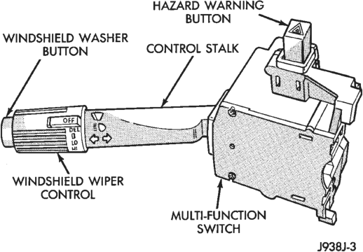
The front wiper and washer switches are contained in the multi-function switch assembly. The multifunction switch assembly is mounted to the left side of the steering column. This switch contains circuitry for the following functions:
• Turn signals • Hazard warning • Headlamp beam selection • Headlamp optical horn • Windshield wipers • Windshield washers. The information contained in this group addresses only the switch functions for the wiper and washer systems. For information relative to the other switch functions, refer to the appropriate group. However, the multi-function switch cannot be repaired. If any function of the switch is faulty, the entire switch assembly must be replaced.
REAR
The single two-function rear wiper switch is part of the right switch pod unit, which is located on the instrument panel just right of the steering column. The rear wiper switch controls the rear wiper and washer functions. The sliding-type switch features a detent in the On and Delay positions. The switch knob is depressed to actuate the rear washer switch, and activate the rear washer system. Both the rear wiper and rear washer motors will operate continuously for as long as the switch is held in the momentary Wash position. The rear wiper switch cannot be repaired and, if faulty, the right switch pod unit must be replaced.
BODY CONTROL MODULE
A Body Control Module (BCM) is used on this model to control and integrate many of the vehicle’s electrical functions and features. The BCM contains a central processing unit and interfaces with other modules in the vehicle on the Chrysler Collision Detection (CCD) data bus network.
The CCD data bus network allows the sharing of sensor information. This helps to reduce wiring harness complexity, reduce internal controller hardware, and reduce component sensor current loads. At the same time, this system provides increased reliability, enhanced diagnostics, and allows the addition of many new feature capabilities.
Some of the functions and features that the BCM supports and controls are the speed sensitive intermittent wipe, pulse wipe, and wipe-after-wash modes. The BCM is programmed to energize the intermittent wipe relay in response to certain inputs from the multi-function switch and the wiper motor park switch. For the speed sensitive intermittent wipe feature, the BCM also uses an input from the vehicle speed sensor, which is received on the CCD data bus from the Powertrain Control Module (PCM).
The BCM is mounted under the left end of the instrument panel, behind the instrument panel support armature and below the left switch pod. Refer to Group 8E - Instrument Panel Systems for removal and installation procedures. For diagnosis of the BCM or the CCD data bus, refer to the proper Body Diagnostic Procedures Manual. The BCM can only be serviced by an authorized repair station. Refer to the Warranty Policies and Procedures Manual for a listing of authorized repair stations.
INTERMITTENT WIPE RELAY
The intermittent wipe relay is a International Standards Organization (ISO) micro-relay. The terminal designations and functions are the same as a conventional ISO relay. However, the micro-relay terminal orientation (or footprint) is different, current capacity is lower, and the relay case dimensions are smaller than on the conventional ISO relay.
The intermittent wipe relay is a electro-mechanical device that switches current to the wiper motor or wiper motor park switch when the relay is energized or de-energized by the body control module in response to the appropriate inputs from the wiper (multi-function) switch. See the Diagnosis and Testing section of this group for more information on the intermittent wipe relay.
The intermittent wipe relay is located in the Power Distribution Center (PDC), in the engine compartment. Refer to the PDC label for relay identification and location.
WASHER RESERVOIR
A single washer fluid reservoir is used for both the front and rear washer systems. The washer fluid reservoir is mounted to the left front inner fender shield, behind the front wheelhouse in the engine compartment.
Each washer pump and motor unit has a threaded nipple, which is installed through a rubber grommet seal inserted in a hole in the bottom of the reservoir. A plastic nut and washer secures the washer pump nipple from the inside of the reservoir, and can be accessed through the reservoir filler neck.
The reservoir have a provision for the optional low washer fluid level sensor. Refer to Group 8E - Instrument Panel Systems for diagnosis and service of the sensor. The reservoir and filler cap are each available for service.
WASHER PUMPS
The washer pumps and motors are mounted near the bottom of the washer reservoir. A threaded nipple on the pump housing passes through a grommet in the bottom of the reservoir. A nut and washer is installed on the nipple from inside the reservoir.
A permanently lubricated and sealed motor is coupled to a rotor-type pump. Washer fluid is gravity-fed from the reservoir to the pump. The pump then pressurizes the fluid and forces it through the plumbing to the nozzles, when the motor is energized. The pump and motor cannot be repaired. If faulty, the entire washer pump and motor unit must be replaced.
WASHER NOZZLES AND PLUMBING
FRONT
Pressurized washer fluid is fed through a single hose, attached to a nipple on the front washer pump, to a tee fitting located in the cowl plenum area beneath the cowl plenum cover/grille panel. Hoses from the tee fitting are routed to the two nozzles, which are snapped into openings in the cowl plenum cover/grille panel below the windshield. The two fluidic washer nozzles are not adjustable. The nozzles cannot be repaired and, if faulty, must be replaced.
REAR
Pressurized washer fluid is fed through a single hose, attached to a nipple on the rear washer pump, to the liftgate. The hose is routed, from the front of the vehicle to the liftgate, with the driver’s side body wiring harness. Above the liftgate opening, the hose connects to a check valve, which prevents washer fluid drain-back or siphoning from occurring. From the check valve, another single hose is routed through holes and grommets in the liftgate opening panel and the liftgate inner panel to the washer nozzle. The nozzle snaps into a hole in the liftgate outer panel, above the liftgate glass. Both the nozzle and check valve are not repairable and, if faulty, must be replaced.
DIAGNOSIS AND TESTING
WIPER SYSTEMS
FRONT
If the problem being diagnosed involves only the pulse wipe or wipe-after-wash modes, see the Washer System diagnosis in this group. For circuit descriptions and diagrams, refer to 8W-53 - Wipers in Group 8W - Wiring Diagrams.
WARNING: ON VEHICLES EQUIPPED WITH AIR- BAGS, REFER TO GROUP 8M - PASSIVE RESTRAINT SYSTEMS BEFORE ATTEMPTING STEERING WHEEL, STEERING COLUMN, OR INSTRUMENT PANEL COMPONENT DIAGNOSIS OR SERVICE. FAILURE TO TAKE THE PROPER PRE- CAUTIONS COULD RESULT IN ACCIDENTAL AIR- BAG DEPLOYMENT AND POSSIBLE PERSONAL INJURY.
(1) Remove the circuit breaker from the junction block and turn the ignition switch to the Accessory or On position. Measure the voltage at the battery side of the circuit breaker. The meter should read battery voltage. If OK, go to Step 2. If not OK, repair the circuit from the ignition switch as required.
(2) Measure the voltage at the wiper system side of the circuit breaker. The meter should read battery voltage. If OK, go to Step 3. If not OK, replace the faulty circuit breaker.
(3) Disconnect the multi-function switch connector. Turn the ignition switch to the Accessory or On position. Measure the voltage at the fused ignition switch output (F86) circuit cavity of the multi-function switch connector. The meter should read battery voltage. If OK, go to Step 4. If not OK, repair the open circuit as required.
(4) If the problem being diagnosed involves only the intermittent wipe feature, go to Step 5. If the problem being diagnosed involves all wiper modes, or only the Low and/or High speed modes, go to Step 7.
(5) Turn the ignition switch to the Off position. Disconnect and isolate the battery negative cable. Unplug the white 24-way body control module connector. Check for continuity between the wiper switch mode sense cavities of the multi-function switch and body control module connectors. There should be continuity. If OK, go to Step 6. If not OK, repair the open circuit as required.
(6) Unplug the black 24-way body control module connector. Check for continuity between the windshield wiper switch signal cavities of the multi-function switch and body control module connectors. There should be continuity. If OK, see the Intermittent Wipe Relay diagnosis in this group. If not OK, repair the open circuit as required.
(7) Turn the ignition switch to the Off position. Check for continuity between the two wiper switch low speed output circuit cavities of the multi-function switch connector. There should be continuity. If OK, go to Step 8. If not OK, repair the open circuit as required.
(8) Test the multi-function switch, as described in this group. If the switch tests OK, reinstall the switch connector and go to Step 9. If not OK, replace the faulty switch and test the wiper system operation. If still not OK, go to Step 9.
(9) Measure the resistance between the ground circuit cavity of the wiper motor connector and a good ground. The meter should read zero ohms. If OK, go to Step 10. If not OK, repair the circuit to ground as required.
(10) Turn the ignition switch to the Accessory or On position. Place the multi-function switch in the positions indicated in the tests below, and check for voltage at the wiper motor connector.
(a) Measure the voltage at the fused ignition switch output circuit cavity of the connector with the wiper switch in any position. The meter should read battery voltage. If OK, go to Step 2. If not OK, repair the open circuit as required.
(b) Measure the voltage at the wiper switch low speed output circuit cavity of the wiper motor connector with the wiper switch in the Low position. The meter should read battery voltage. If OK, go to Step 3. If not OK, repair the open circuit as required.
(c) Measure the voltage at the wiper switch high speed output circuit cavity of the connector with the wiper switch in the High position. The meter should read battery voltage. If OK, go to Step 4. If not OK, repair the open circuit as required.
(d) Measure the voltage at the wiper park switch sense circuit cavity of the connector with the wiper switch in the Low or High position, then move the switch to the Off position. The meter should switch between battery voltage and zero volts while the wipers are cycling. Then, the meter should read battery voltage when the switch is moved to the Off position until the wipers park, and then read a steady zero volts. If not OK, replace the faulty wiper motor.
REAR
For circuit descriptions and diagrams, refer to 8W-53 - Wipers in Group 8W - Wiring Diagrams.
WARNING: ON VEHICLES EQUIPPED WITH AIR- BAGS, REFER TO GROUP 8M - PASSIVE RESTRAINT SYSTEMS BEFORE ATTEMPTING STEERING WHEEL, STEERING COLUMN, OR INSTRUMENT PANEL COMPONENT DIAGNOSIS OR SERVICE. FAILURE TO TAKE THE PROPER PRE- CAUTIONS COULD RESULT IN ACCIDENTAL AIR- BAG DEPLOYMENT AND POSSIBLE PERSONAL INJURY.
(1) Check the fuse in the junction block. If OK, go to Step 2. If not OK, replace the faulty fuse.
(2) Turn the ignition switch to the On position. Check for battery voltage at the fused ignition switch output circuit cavity of the rear wiper switch connector. If OK, go to Step 3. If not OK, repair the open circuit as required.
(3) Test the rear wiper switch, as described in this group. If OK, go to Step 4. If not OK, replace the faulty switch.
(4) Turn the ignition switch to the Off position. Remove the liftgate inner trim panel. Measure the resistance between the ground circuit cavity of the rear wiper motor connector and a good ground. The meter should read zero ohms. If OK, go to Step 5. If not OK, repair the circuit to ground as required.
(5) Check for continuity between the liftgate ajar switch sense cavity of the wiper motor connector and a good ground. There should be continuity with liftgate and/or liftglass (if equipped) open, and no continuity with the liftgate and liftglass (if equipped) closed. If OK, go to Step 6. If not OK, repair the liftgate and/or liftglass ajar circuit or switch as required.
(6) Turn the ignition switch to the On position, and place the rear wiper switch in the Wipe position. Measure the voltage at the rear wiper motor control circuit cavity of the motor connector. Repeat the test for the rear wiper motor control (intermittent) circuit cavity with the rear wiper switch in the Intermittent position, then at the rear washer motor control circuit cavity with the rear wiper switch in the Wash position. In each case, the meter should read battery voltage. If OK, replace the faulty rear wiper motor. If not OK, repair the open circuit(s) as required.
WASHER SYSTEMS
FRONT
The diagnosis found here addresses an inoperative washer pump or wipe-after-wash feature. If the washer pump operates, but no washer fluid is emitted from the washer nozzles, be certain to check the fluid level in the reservoir. Check for ice or other foreign material in the reservoir, and for pinched, disconnected, broken, or incorrectly routed washer system plumbing. For circuit descriptions and diagrams, refer to 8W-53 - Wipers in Group 8W - Wiring Diagrams.
WARNING: ON VEHICLES EQUIPPED WITH AIR- BAGS, REFER TO GROUP 8M - PASSIVE RESTRAINT SYSTEMS BEFORE ATTEMPTING STEERING WHEEL, STEERING COLUMN, OR INSTRUMENT PANEL COMPONENT DIAGNOSIS OR SERVICE. FAILURE TO TAKE THE PROPER PRE- CAUTIONS COULD RESULT IN ACCIDENTAL AIR- BAG DEPLOYMENT AND POSSIBLE PERSONAL INJURY.
(1) Turn the ignition switch to the On position. Turn the wiper switch to the Low or High speed position. Check whether the wipers operate. If OK, go to Step 2. If not OK, see the Windshield Wiper System diagnosis in this group.
(2) Turn the wiper switch to the Off position. Depress the washer switch for less than one-half second. The wipers should operate for one sweep cycle and then park. Depress the washer switch for more than one-half second. The washer pump should operate and the wipers should operate for two sweep cycles after the switch is released before they park. If the wipers are OK, but the washers are not, go to Step 3. If the washers are OK, but the wipers are not, go to Step 5.
(3) Turn the ignition switch to the Off position. Unplug the front washer pump connector. Measure the resistance between the ground circuit cavity of the pump connector and a good ground. The meter should read zero ohms. If OK, go to Step 4. If not OK, repair the ground circuit as required.
(4) Turn the ignition switch to the On position. Depress the washer switch. Measure the voltage at the washer switch output circuit cavity of the front washer pump connector. The meter should read battery voltage. If OK, replace the faulty pump. If not OK, repair the open circuit as required.
(5) Disconnect and isolate the battery negative cable. Unplug the white 24-way connector from the body control module. Connect the battery negative cable. Turn the ignition switch to the On position. Check for battery voltage at the washer switch output circuit cavity of the white body control module connector. If OK, see the Intermittent Wipe Relay diagnosis in this group. If not OK, repair the open circuit as required.
REAR
The diagnosis found here addresses an inoperative washer pump. If the washer pump operates, but no washer fluid is emitted from the washer nozzles, be certain to check the fluid level in the reservoir. Check for ice or other foreign material in the reservoir, and for pinched, disconnected, broken, or incorrectly routed washer system plumbing. For circuit descriptions and diagrams, refer to 8W-53 - Wipers in Group 8W - Wiring Diagrams.
WARNING: ON VEHICLES EQUIPPED WITH AIR- BAGS, REFER TO GROUP 8M - PASSIVE RESTRAINT SYSTEMS BEFORE ATTEMPTING STEERING WHEEL, STEERING COLUMN, OR INSTRUMENT PANEL COMPONENT DIAGNOSIS OR SERVICE. FAILURE TO TAKE THE PROPER PRE- CAUTIONS COULD RESULT IN ACCIDENTAL AIR- BAG DEPLOYMENT AND POSSIBLE PERSONAL INJURY.
(1) Turn the ignition switch to the On position. Place the rear wiper/washer switch in the Wipe position. Check whether the rear wiper is operating. If OK, go to Step 2. If not OK, see the Rear Wiper System diagnosis in this group.
(2) Turn the ignition switch to the Off position and unplug the rear washer pump connector. Measure the resistance between the ground circuit cavity of the pump connector and a good ground. The meter should read zero ohms. If OK, go to Step 3. If not OK, repair the circuit to ground as required.
(3) Turn the ignition switch to the On position. Depress the rear washer switch. Measure the voltage at the rear washer motor control circuit cavity of the rear washer pump connector. The meter should read battery voltage. If OK, replace the faulty pump. If not OK, repair the open circuit as required.
WIPER AND WASHER SWITCHES
FRONT
Perform the diagnosis for the wiper and/or washer systems as described in this group before testing the multi-function switch. For circuit descriptions and diagrams, see 8W-53 - Wipers in Group 8W - Wiring Diagrams.
WARNING: ON VEHICLES EQUIPPED WITH AIR- BAGS, REFER TO GROUP 8M - PASSIVE RESTRAINT SYSTEMS BEFORE ATTEMPTING STEERING WHEEL, STEERING COLUMN, OR INSTRUMENT PANEL COMPONENT DIAGNOSIS OR SERVICE. FAILURE TO TAKE THE PROPER PRE- CAUTIONS COULD RESULT IN ACCIDENTAL AIR- BAG DEPLOYMENT AND POSSIBLE PERSONAL INJURY.
(1) Disconnect and isolate the battery negative cable.
(2) Disconnect the multi-function switch connector as described in this group.
(3) Using an ohmmeter, perform the switch continuity checks at the switch terminals as shown in the chart (Fig. 2).
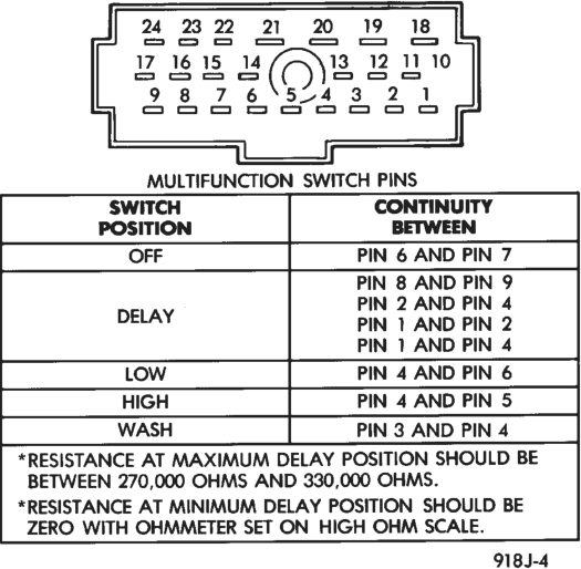
(4) If the switch fails any of the continuity checks, replace the faulty switch.
REAR
Perform the diagnosis for the rear wiper and/or washer systems as described in this group before testing the rear wiper and washer switch. For circuit descriptions and diagrams, see 8W-53 - Wipers in Group 8W - Wiring Diagrams.
WARNING: ON VEHICLES EQUIPPED WITH AIR- BAGS, REFER TO GROUP 8M - PASSIVE RESTRAINT SYSTEMS BEFORE ATTEMPTING
STEERING WHEEL, STEERING COLUMN, OR INSTRUMENT PANEL COMPONENT DIAGNOSIS OR SERVICE. FAILURE TO TAKE THE PROPER PRE- CAUTIONS COULD RESULT IN ACCIDENTAL AIR- BAG DEPLOYMENT AND POSSIBLE PERSONAL INJURY.
(1) Remove the rear wiper and washer switch as described in this group.
(2) Using an ohmmeter, check the switch continuity at the switch terminals as follows:
a. With the switch in the Off position, there should be no continuity between any two switch terminals.
b. With the switch knob depressed in the Wash position, there should be continuity between the fused ignition switch output circuit and the rear washer motor control circuit terminals.
c. With the switch in the Intermittent position, there should be continuity between the fused ignition switch output circuit and the rear wiper motor control (intermittent) circuit terminals.
d. With the switch in the On position, there should be continuity between the fused ignition switch output circuit and the rear wiper motor control circuit terminals.
(3) If the switch fails any of the continuity checks, replace the faulty switch.
INTERMITTENT WIPE RELAY
For circuit descriptions and diagrams, refer to 8W-53 - Wipers in Group 8W - Wiring Diagrams.
WARNING: ON VEHICLES EQUIPPED WITH AIR- BAGS, REFER TO GROUP 8M - PASSIVE RESTRAINT SYSTEMS BEFORE ATTEMPTING STEERING WHEEL, STEERING COLUMN, OR INSTRUMENT PANEL COMPONENT DIAGNOSIS OR SERVICE. FAILURE TO TAKE THE PROPER PRE- CAUTIONS COULD RESULT IN ACCIDENTAL AIR- BAG DEPLOYMENT AND POSSIBLE PERSONAL INJURY.
RELAY TESTS
The intermittent wipe relay is located in the Power Distribution Center (PDC) in the engine compartment. Refer to the PDC label for intermittent wipe relay identification and location.
Remove the intermittent wipe relay from the PDC as described in this group to perform the following tests:
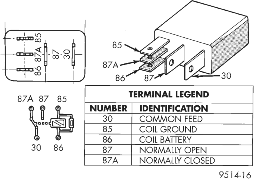
(1) A relay in the de-energized position should have continuity between terminals 87A and 30, and no continuity between terminals 87 and 30. If OK, go to Step 2. If not OK, replace the faulty relay.
(2) Resistance between terminals 85 and 86 (electromagnet) should be 7565 ohms. If OK, go to Step 3. If not OK, replace the faulty relay. (3) Connect a battery to terminals 85 and 86. There should now be continuity between terminals 30 and 87, and no continuity between terminals 87A and 30. If OK, see the Relay Circuit Test in this group. If not OK, replace the faulty relay.
Intermittent Wipe Relay
RELAY CIRCUIT TESTS
(1) The relay common feed terminal cavity (30) is connected to the wiper (multi-function) switch. There should be continuity between the cavity for relay terminal 30 and the two fused ignition switch output (V6) circuit cavities of the multi-function switch connector at all times. If OK, go to Step 2. If not OK, repair the open circuit(s) to the multi-function switch as required.
(2) The relay normally closed terminal (87A) is connected to terminal 30 in the de-energized position. There should be continuity between the cavity for relay terminal 87A and the wiper park switch sense circuit cavities of the wiper motor and the white 24-way body control module connectors at all times. If OK, go to Step 3. If not OK, repair the open circuit(s) to the wiper motor and body control module as required.
(3) The relay normally open terminal (87) is connected to the common feed terminal (30) in the energized position. There should be battery voltage at the cavity for relay terminal 87 with the ignition switch in the On or Accessory positions. If OK, go to Step 4. If not OK, repair the open circuit to the ignition switch as required.
(4) The coil battery terminal (86) is connected to the electromagnet in the relay. There should be battery voltage at the cavity for relay terminal 86 with the ignition switch in the On or Accessory positions. If OK, go to Step 5. If not OK, repair the open circuit to the ignition switch as required.
(5) The coil ground terminal (85) is connected to the electromagnet in the relay. It is grounded by the Body Control Module (BCM) to energize the relay and cycle the wiper motor. Check for continuity to the intermittent wiper relay control circuit cavity of the white 24-way BCM connector. There should be continuity. If OK, refer to the proper Body Diagnostic Procedures Manual for diagnosis of the BCM. If not OK, repair the open circuit to the BCM as required.
REMOVAL AND INSTALLATION
WIPER BLADES AND ELEMENTS
FRONT
Note that the pinch-release for the wiper element should always be oriented towards the end of the wiper blade that is nearest to the wiper pivot. To remove the wiper blade and/or element, proceed as follows:
(1) Turn the wiper/washer switch to the On position. By turning the ignition switch to the On and Off positions, cycle the wiper blades to a convenient working location on the windshield.
(2) Lift the wiper arm to raise the wiper blade and element off of the windshield glass.
(3) Remove the wiper blade from the wiper arm, or the wiper element from the wiper blade as follows:
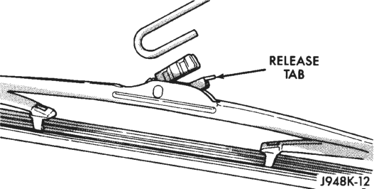
(a) To remove the wiper blade from the wiper arm, push the release tab under the arm tip and slide the blade away from the tip towards the pivot end of the arm (Fig. 3).
(b) To remove the wiper element from the wiper blade, pinch the notched (pivot) end of the wiper element tightly between the thumb and forefinger (Fig. 4). Then, pull the element firmly towards the wiper pivot to release the wiper blade claw from the wiper element retaining pocket. Once the claw is released from the pocket, the element will slide easily out of the remaining claws.
Typical
(4) Install the wiper blade on the wiper arm, or the wiper element in the wiper blade as follows:
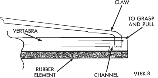
(a) To install the wiper blade on the wiper arm, slide the blade retainer into the U-shaped formation on the tip of the wiper arm until the release tab snaps into its locked position. Be certain that the pinch-release for the wiper element is oriented towards the end of the wiper blade that is nearest to the wiper pivot.
(b) To install the wiper element in the wiper blade, be certain that the metal element rails (vertebra) are properly seated in the slots on either side of the rubber element. Starting at the wiper pivot end of the blade, slide the element through each pair of wiper blade claws. The element is fully installed when the claws on the wiper pivot end of the blade are engaged in the wiper element retaining pockets.
REAR
Note that the pinch-release for the wiper element should always be oriented towards the end of the wiper blade that is nearest to the wiper pivot. To remove the wiper blade and/or element, proceed as follows:
(1) Lift the wiper arm to raise the wiper blade and element off of the liftgate glass.
(2) Remove the wiper blade from the wiper arm, or the wiper element from the wiper blade as follows:
(a) To remove the wiper blade from the wiper arm, push the release tab under the arm tip and slide the blade away from the tip towards the pivot end of the arm (Fig. 3).
(b) To remove the wiper element from the wiper blade, pinch the notched (pivot) end release clip of the wiper element tightly between the thumb and forefinger. Then, pull the element firmly towards the wiper pivot to release the wiper element release clip from the wiper blade claw. Once the clip is released from the claw, the element will slide easily out of the remaining claws. (3) Install the wiper blade on the wiper arm, or the wiper element in the wiper blade as follows:
(a) To install the wiper blade on the wiper arm, slide the blade retainer into the U-shaped formation on the tip of the wiper arm until the release tab snaps into its locked position. Be certain that the pinch-release clip for the wiper element is oriented towards the end of the wiper blade that is nearest to the wiper pivot.
(b) To install the wiper element in the wiper blade, start at the wiper pivot end of the blade and slide the element through each pair of wiper blade claws. The element is fully installed when the claws on the wiper pivot end of the blade are engaged in the wiper element retaining clip notches.
WIPER ARMS
FRONT
CAUTION: The use of a screwdriver or other prying tool to remove a wiper arm may distort it. This distortion could allow the arm to come off of the pivot shaft, regardless of how carefully it is installed.
(1) Open the vehicle’s hood. (2) Lift the wiper arm to permit the latch to be pulled out to its holding position, then release the arm (Fig. 5). The arm will remain off the windshield with the latch in this position.
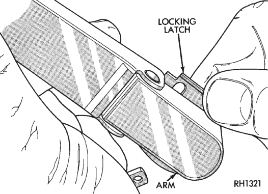
(3) Remove the arm from the pivot using a rocking motion.
(4) Install the arm and blade with the wiper motor in the Park position. See the Wiper Arm Installation illustration (Fig. 6). Mount the arms on the pivot shafts so that the distance from the lower edge of the wiper arm tip to the upper edge of the lower windshield moulding is:
• 25 - 52 mm (0.98 - 2.04 inch) on the driver’s side • 33 - 62 mm (1.29 - 2.44 inch) on the passenger’s side.
(5) Lift the wiper arm away from the windshield slightly to relieve the spring tension on the locking latch. Push the latch into the locked position and slowly release the arm until the wiper blade rests on the windshield.
(6) Operate the wipers with the windshield glass wet, then turn the wiper switch to the Off position. Check for the correct wiper arm positioning and readjust if required.
REAR
(1) Remove the wiper arm assembly from the pivot pin by lifting the pivot cover and removing the retaining nut (Fig. 7).
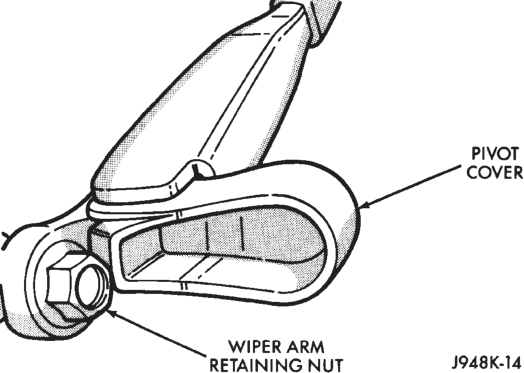
(2) Remove the wiper arm from the motor output shaft.
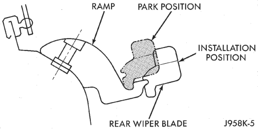
(3) Install the rear wiper arm with the wiper motor in the Park position. Place the rear wiper blade in the installation position on the ramp (Fig. 8) and tighten the retaining nut to 18 N·m (160 in. lbs.).
(4) Close the pivot cover and move the rear wiper blade to the park position on the ramp.
WIPER MOTOR
FRONT
(1) Disconnect and isolate the battery negative cable.
(2) Remove the wiper arms as described in this group.
(3) Remove the screws from the cowl plenum cover/grille panel.
(4) Lift the cowl plenum cover/grille panel and disconnect the washer hose at the tee fitting. Remove the cowl plenum cover/grille panel.
(5) Remove the five wiper linkage cowl mounting bracket bolts (Fig. 9).
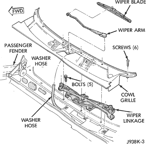
(6) Disconnect the wiper motor wiring harness and remove the motor and linkage assembly from the cowl plenum.
(7) Turn the linkage and motor assembly over and remove the nut holding the wiper motor crank arm to the output shaft.
(8) Remove the three screws holding the motor to the linkage assembly bracket and remove the motor.
(9) Reverse the removal procedures to install. Tighten the mounting hardware as follows:
• wiper motor screws - 5-7 N·m (44-62 in. lbs.) • crank arm nut - 10-12 N·m (88-106 in. lbs.) • linkage assembly mounting bolts - 8 N·m (72 in. lbs.).
REAR
(1) Disconnect and isolate the battery negative cable.
(2) Remove the rear wiper arm as described in this group.
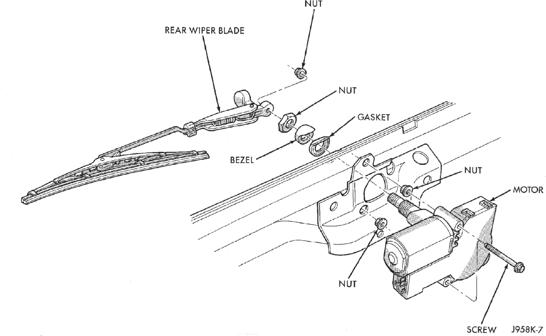
(3) Remove the motor retaining nut (Fig. 10). (4) Remove the external bezel and gasket. (5) Remove the liftgate inner trim panel. (6) Disconnect the rear wiper motor wiring harness.
(7) Remove the wiper motor mounting screws. (8) Remove the wiper motor. (9) Reverse the removal procedures to install. Tighten the mounting hardware as follows:
• motor mounting screws - 1-1.7 N·m (10-15 in. lbs.)
• motor mounting nut - 4-5.6 N·m (35-50 in. lbs.).
WIPER LINKAGE AND PIVOTS
The wiper linkage and pivots can only be removed from the vehicle as a unit with the wiper motor. See Wiper Motors in this group for the service procedures.
INTERMITTENT WIPE RELAY
(1) Disconnect and isolate the battery negative cable.
(2) Remove the cover from the Power Distribution Center (PDC) (Fig. 11).
(3) Refer to the label on the PDC for intermittent wipe relay identification and location.
(4) Remove the intermittent wipe relay by unplugging it from the PDC.
(5) Install the intermittent wipe relay by aligning the relay terminals with the cavities in the PDC and pushing the relay firmly into place.
(6) Install the PDC cover. (7) Connect the battery negative cable. (8) Test the relay operation.
WIPER AND WASHER SWITCHES
FRONT
WARNING: ON VEHICLES EQUIPPED WITH AIR- BAGS, REFER TO GROUP 8M - PASSIVE RESTRAINT SYSTEMS BEFORE ATTEMPTING STEERING WHEEL, STEERING COLUMN, OR INSTRUMENT PANEL COMPONENT DIAGNOSIS OR SERVICE. FAILURE TO TAKE THE PROPER PRE- CAUTIONS COULD RESULT IN ACCIDENTAL AIR- BAG DEPLOYMENT AND POSSIBLE PERSONAL INJURY.
(1) Disconnect and isolate the battery negative cable.
(2) Remove the tilt steering column lever, if equipped.
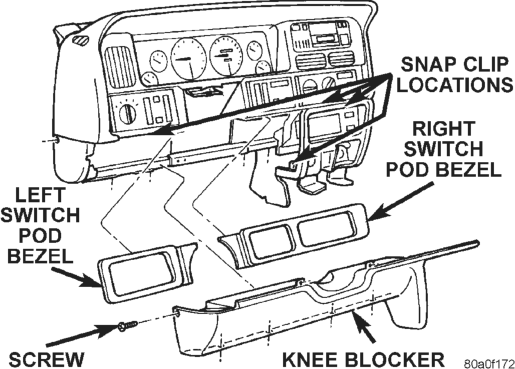
(3) Using a trim stick or other suitable wide flatbladed tool, pry gently around the edges of the switch pod bezels and remove both bezels.
(4) Remove one screw on each side of the steering column on the upper edge of the knee blocker/steering column cover (Fig. 12).
(5) Remove one screw securing the left end of the knee blocker to the instrument panel.
(6) Remove the four screws securing the lower edge of the knee blocker to the lower instrument panel reinforcement.
(7) Using a trim stick or other suitable wide flatbladed tool, gently pry the edges of the knee blocker away from the instrument panel at the locations shown (Fig. 12).
(8) Remove the knee blocker/steering column cover from the vehicle.
(9) Remove both the upper and lower shrouds from the steering column (Fig. 13).
(10) Remove the lower fixed column shroud.
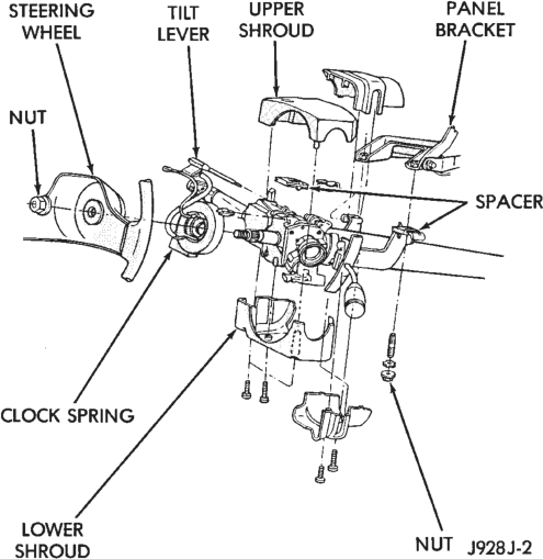
(11) Loosen the steering column upper bracket nuts. Do not remove the nuts.
(12) Move the upper fixed column shroud to gain access to the rear of the multi-function switch (Fig. 14). (13) Remove the multi-function switch tamper proof mounting screws (a Snap On tamper proof torx bit TTXR20B2 or equivalent is required).
(14) Gently pull the switch away from the column. Loosen the connector screw. The screw will remain in the connector.
(15) Remove the wiring connector from the multifunction switch.
(16) Reverse the removal procedures to install. Tighten the fasteners as follows:
• Multi-function switch connector screw - 1.9 N·m (17 in. lbs.)
• Multi-function switch retaining screws - 1.9 N·m (17 in. lbs.)
• Steering column upper bracket nuts - 12 N·m (110 in. lbs.).
REAR
WARNING: ON VEHICLES EQUIPPED WITH AIR- BAGS, REFER TO GROUP 8M - PASSIVE RESTRAINT SYSTEMS BEFORE ATTEMPTING STEERING WHEEL, STEERING COLUMN, OR INSTRUMENT PANEL COMPONENT DIAGNOSIS OR SERVICE. FAILURE TO TAKE THE PROPER PRE- CAUTIONS COULD RESULT IN ACCIDENTAL AIR- BAG DEPLOYMENT AND POSSIBLE PERSONAL INJURY.
(1) Disconnect and isolate the battery negative cable.
(2) Using a trim stick or other suitable wide flatbladed tool, pry gently around the edges of the right switch pod bezel and remove the bezel.
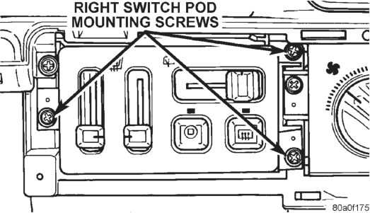
(3) Remove the three screws securing the right switch pod to the instrument panel (Fig. 15).
(4) Pull the right switch pod out from the instrument panel far enough to unplug the wiring connectors.
(5) Remove the right switch pod from the instrument panel.
(6) Reverse the removal procedures to install.
WASHER PUMPS AND RESERVOIR
(1) Disconnect and isolate the battery negative cable.
(2) Disconnect the wiring from the fluid level sensor, if equipped.
(3) Remove the three screws securing the washer reservoir (Fig. 16).
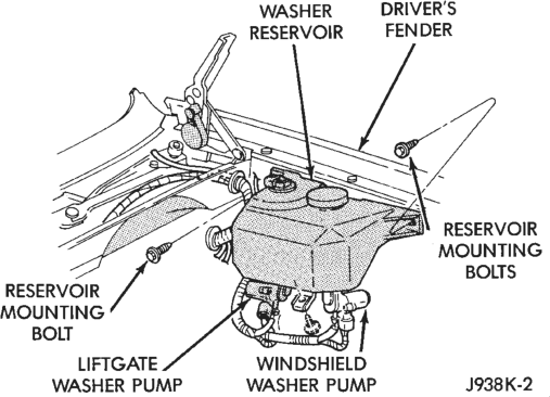
(4) Disconnect the hoses from the washer pumps, and drain the solvent from the reservoir into a clean container for reuse.
(5) Use a deep socket and extension, inserted through the reservoir filler neck, to remove the washer pump filter/nuts from inside of the reservoir.
(6) Remove the pumps from the reservoir. (7) Reverse the removal procedures to install.