Vehicle Theft/Security Systems — 1996 Jeep Grand Cherokee ZJ Service Manual
Pages 448–455 · 8 pages · 1 words repaired
Depressing the Panic button on the RKE transmitter will also disarm the VTSS, but the horn will sound and the lights will flash for about three minutes as part of the Panic feature. Refer to Group 8P - Power Lock Systems for more information on the Panic feature.
POWER-UP MODE
When the armed VTSS senses that the battery has been disconnected and reconnected, it enters its power-up mode. In the power-up mode the alarm system remains armed following a battery failure or disconnect. If the VTSS was armed prior to a battery disconnect or failure, the system will have to be actively or passively disarmed following a battery reconnection.
The power-up mode will also apply if the battery goes dead while the system is armed, and battery jump-starting is attempted. The engine no-run feature will prevent the engine from starting until the alarm system has been actively or passively disarmed.
TAMPER ALERT
The VTSS tamper alert will sound the horn three times upon disarming, if the alarm was activated and has since timed-out (about 18 minutes). This feature alerts the driver that the VTSS was activated.
DESCRIPTION AND OPERATION
BODY CONTROL MODULE
A Body Control Module (BCM) is used on this model to control and integrate many of the vehicle’s electrical functions and features. The BCM contains a central processing unit and interfaces with other modules in the vehicle on the Chrysler Collision Detection (CCD) data bus network.
The CCD data bus network allows the sharing of sensor information. This helps to reduce wiring harness complexity, reduce internal controller hardware, and reduce component sensor current loads. At the same time, this system provides increased reliability, enhanced diagnostics, and allows the addition of many new feature capabilities.
One of the functions and features that the BCM supports and controls, is the Vehicle Theft Security System (VTSS). In addition to the information received on the CCD data bus, the BCM receives hard wired inputs from the door ajar, door lock cylinder, hood, liftgate ajar, liftgate lock cylinder, and liftglass ajar switches. In its role as the VTSS controller, the programming in the BCM allows it to process the information from all of its inputs and send control outputs to the auto headlamp relay, horn relay, park lamp relay, powertrain control module, and the security set lamp.
The BCM is mounted under the left end of the instrument panel, behind the instrument panel support armature and below the left switch pod. Refer to Group 8E - Instrument Panel Systems for removal and installation procedures. For diagnosis of the BCM or the CCD data bus, refer to the proper Body Diagnostic Procedures Manual. The BCM can only be serviced by an authorized repair station. Refer to the Warranty Policies and Procedures Manual for a listing of authorized repair stations.
HOOD SWITCH
The hood switch is mounted to the right inner fender ledge, under the hood and near the battery. It is a plunger-type switch that is case grounded to the fender shield. When the hood is open the switch is closed, and when the hood is closed the switch is open.
The hood switch cannot be repaired and, if faulty or damaged, it must be replaced.
DOOR AJAR SWITCH
The door ajar switches are mounted to the pillar in the rear of each door opening. They are plunger-type switches that are case grounded to the pillar. When the door is open the switch is closed, and when the door is closed the switch is open.
The door ajar switches cannot be repaired and, if faulty or damaged, they must be replaced.
DOOR LOCK CYLINDER SWITCH
The door lock cylinder switches are mounted to the back of the key lock cylinder inside each front door. They are normally-open momentary switches that close to ground only when the lock cylinder is rotated to the unlock position.
The door lock cylinder switches cannot be repaired and, if faulty or damaged, they must be replaced.
LIFTGATE AJAR SWITCH
The liftgate ajar switch is integral to the liftgate latch assembly on the liftgate. It is a momentarytype switch that is open when the liftgate is closed, and closed when the liftgate is open.
The liftgate ajar switch cannot be repaired and, if faulty or damaged, the liftgate latch assembly must be replaced.
LIFTGATE LOCK CYLINDER SWITCH
The liftgate lock cylinder switch is mounted to the back of the key lock cylinder inside the liftgate. It is a normally-open momentary switch that closes to ground only when the lock cylinder is rotated to the unlock position.
The liftgate lock cylinder switch cannot be repaired and, if faulty or damaged, it must be replaced.
LIFTGLASS AJAR SWITCH
The liftglass ajar switch is integral to the liftglass latch assembly on the liftgate. It is a momentarytype switch that is open when the liftglass is closed, and closed when the liftglass is open.
The liftglass ajar switch cannot be repaired and, if faulty or damaged, the liftglass latch assembly must be replaced.
AUTO HEADLAMP RELAY
The auto headlamp relay is a International Standards Organization (ISO) micro-relay. The terminal designations and functions are the same as a conventional ISO relay. However, the micro-relay terminal orientation (or footprint) is different, current capacity is lower, and the relay case dimensions are smaller than on the conventional ISO relay.
The auto headlamp relay is a electro-mechanical device that switches current to the headlamps when the body control module grounds the relay coil. The auto headlamp relay is located in the junction block, on the right cowl side panel below the instrument panel in the passenger compartment.
HORN RELAY
The horn relay is a International Standards Organization (ISO) micro-relay. The terminal designations and functions are the same as a conventional ISO relay. However, the micro-relay terminal orientation (or footprint) is different, current capacity is lower, and the relay case dimensions are smaller than on the conventional ISO relay.
The horn relay is a electro-mechanical device that switches current to the horns when the horn switch or the body control module grounds the relay coil. The horn relay is located in the power distribution center, in the engine compartment.
PARK LAMP RELAY
The park lamp relay is a International Standards Organization (ISO) micro-relay. The terminal designations and functions are the same as a conventional ISO relay. However, the micro-relay terminal orientation (or footprint) is different, current capacity is lower, and the relay case dimensions are smaller than on the conventional ISO relay.
The park lamp relay is a electro-mechanical device that switches current to the park lamps when the body control module grounds the relay coil. The park lamp relay is located in the junction block, on the right cowl side panel below the instrument panel in the passenger compartment.
SET LAMP
The VTSS set lamp is a red light-emitting diode mounted with the auto headlamp ambient light sensor on top of the instrument panel near the left defroster outlet. The set lamp receives fused battery feed at all times and is grounded by the body control module to give a visible indication of the VTSS status.
The set lamp cannot be repaired and, if damaged or faulty, the set lamp/auto headlamp ambient light sensor must be replaced as a unit.
DIAGNOSIS AND TESTING
VEHICLE THEFT SECURITY SYSTEM
The vehicle theft security system should be diagnosed using the DRB scan tool and the proper Body Diagnostic Procedures Manual. Refer to 8W-39 - Vehicle Theft Security System in Group 8W - Wiring Diagrams for complete circuit descriptions and diagrams.
Self-Diagnostics
The vehicle theft security system has a self-diagnostic mode that can be entered using the DRB scan tool. Refer to the proper Body Diagnostic Procedures Manual for more information on this feature.
RELAYS
The horn relay is located in the Power Distribution Center (PDC) in the engine compartment. The auto headlamp and park lamp relays are located in the junction block in the passenger compartment. Each of these relays can be tested as described in the following procedure, however the circuits they are used in vary. To test the relay circuits, refer to the circuit descriptions and diagrams in 8W-39 - Vehicle Theft Security System in Group 8W - Wiring Diagrams.
WARNING: ON VEHICLES EQUIPPED WITH AIR- BAGS, REFER TO GROUP 8M - PASSIVE RESTRAINT SYSTEMS BEFORE ATTEMPTING STEERING WHEEL, STEERING COLUMN, OR INSTRUMENT PANEL COMPONENT DIAGNOSIS OR SERVICE. FAILURE TO TAKE THE PROPER PRE- CAUTIONS COULD RESULT IN ACCIDENTAL AIR- BAG DEPLOYMENT AND POSSIBLE PERSONAL INJURY.
Remove the relay from the PDC or junction block as described in this group to perform the following tests:
(1) A relay in the de-energized position should have continuity between terminals 87A and 30, and no continuity between terminals 87 and 30. If OK, go to Step 2. If not OK, replace the faulty relay.
(2) Resistance between terminals 85 and 86 (electromagnet) should be 7565 ohms. If OK, go to Step 3. If not OK, replace the faulty relay. (3) Connect a battery to terminals 85 and 86. There should now be continuity between terminals 30 and 87, and no continuity between terminals 87A and 30. If OK, test the relay circuits. If not OK, replace the faulty relay.
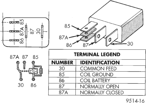
Relay Terminals
REMOVAL AND INSTALLATION
HOOD SWITCH
(1) Disconnect and isolate the battery negative cable.
(2) Remove the screw securing the hood switch to the right inner fender ledge (Fig. 1).
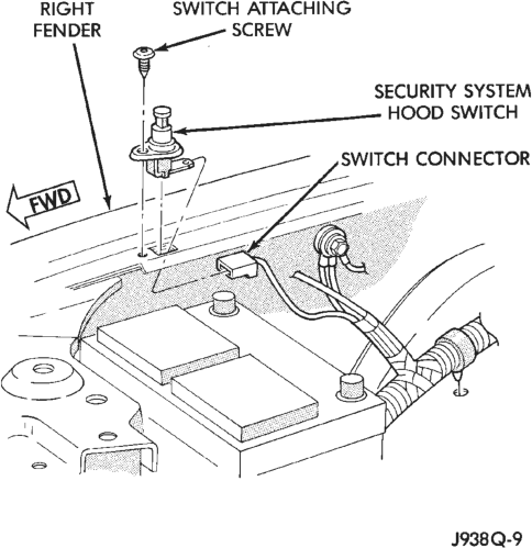
(3) Unplug the wire connector from the switch. (4) Remove the switch from the mounting hole in the inner fender ledge.
(5) Reverse the removal procedures to install. Tighten the switch mounting screw to 1.5 N·m (15 in. lbs.).
DOOR AJAR SWITCH
(1) Disconnect and isolate the battery negative cable.
(2) Remove the screw securing the switch to the pillar at the rear of the door opening (Fig. 2).
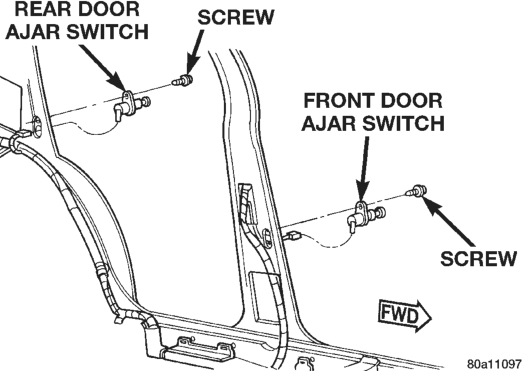
(3) Pull the switch from the mounting hole in the door opening.
(4) Unplug the wire connector from the switch. (5) Reverse the removal procedures to install. Tighten the switch mounting screw to 1.7 N·m (15 in. lbs.).
DOOR LOCK CYLINDER SWITCH
(1) Disconnect and isolate the battery negative cable.
(2) Remove the bezel near the inside door latch release handle by inserting a straight-bladed screwdriver in the notched end and prying gently upwards.
(3) Remove the door trim panel mounting screw located in the bezel opening near the inside door latch release handle (Fig. 3).
(4) Remove the trim cap and screw near the rear of the door armrest.
(5) Remove the trim cap and screw at the upper front corner of the trim panel.
(6) Using a wide flat-bladed tool such as a trim stick, pry the trim panel away from the door around the perimeter and remove the trim panel.
NOTE: To aid in the removal of the trim panel, start at the bottom of the panel.
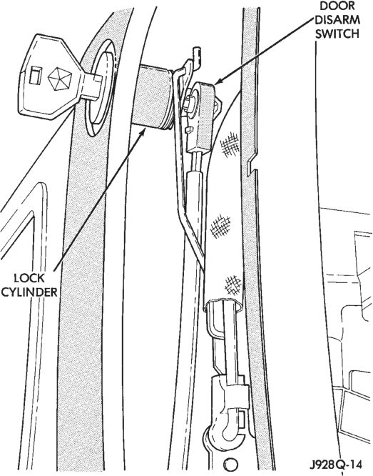
(7) Unplug the wiring connectors from the door multiplex switch module and set the trim panel aside.
(8) Pull the watershield away from the rear access holes in the inner door panel.
(9) Remove the U-clip retainer securing the lock cylinder to the outer door panel (Fig. 4).
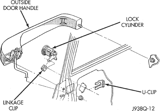
(10) Disconnect the lock cylinder rod from the door latch by unsnapping the retainer from the rod.
(11) Pull the lock cylinder out from the outer door panel far enough to pry the lock cylinder switch off of the back of the lock cylinder (Fig. 5).
(12) Unplug the lock cylinder switch wire harness connector and remove the switch from inside the door.
(13) Reverse the removal procedures to install.
LIFTGATE AJAR SWITCH
(1) Disconnect and isolate the battery negative cable.
Typical
(2) Remove the screws securing the liftgate lower trim panel to the liftgate (Fig. 6).
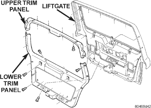
(3) Using a wide flat-bladed tool such as a trim stick, pry the trim panel away from the liftgate around the perimeter and remove the trim panel.
NOTE: To aid in the removal of the trim panel, start at the bottom of the panel.
(4) Remove the three screws securing the liftgate latch to the liftgate (Fig. 7).
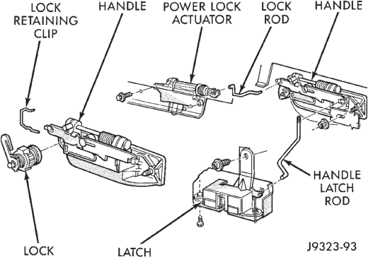
(5) Disconnect the liftgate handle latch actuator rod from the latch.
(6) Unplug the liftgate ajar switch wire connector from the latch.
(7) Remove the latch from the liftgate. (8) Reverse the removal procedures to install. Tighten the latch mounting screws to 7 N·m (62 in lbs.).
LIFTGATE LOCK CYLINDER SWITCH
(1) Disconnect and isolate the battery negative cable.
(2) Remove the screws securing the liftgate lower trim panel to the liftgate (Fig. 8).
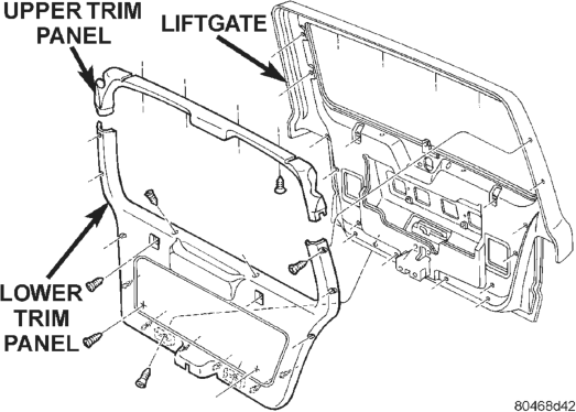
(3) Using a wide flat-bladed tool such as a trim stick, pry the trim panel away from the liftgate around the perimeter and remove the trim panel.
NOTE: To aid in the removal of the trim panel, start at the bottom of the panel.
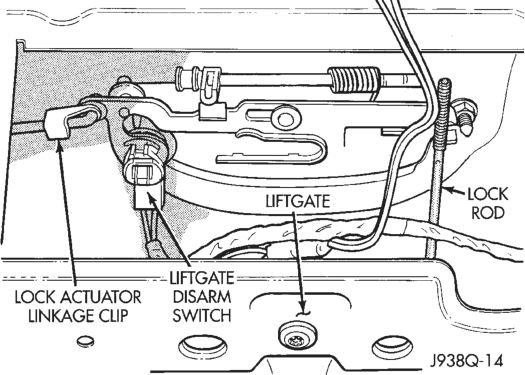
(4) Pry the liftgate lock cylinder switch off of the back of the lock cylinder (Fig. 9).
(5) Unplug the lock cylinder switch wire harness connector and remove the switch from inside the liftgate.
(6) Reverse the removal procedures to install.
LIFTGLASS AJAR SWITCH
(1) Disconnect and isolate the battery negative cable.
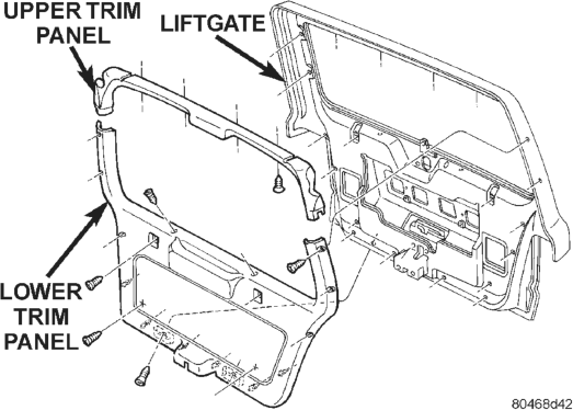
(2) Remove the screws securing the liftgate lower trim panel to the liftgate (Fig. 10).
(3) Using a wide flat-bladed tool such as a trim stick, pry the trim panel away from the liftgate around the perimeter and remove the trim panel.
NOTE: To aid in the removal of the trim panel, start at the bottom of the panel.
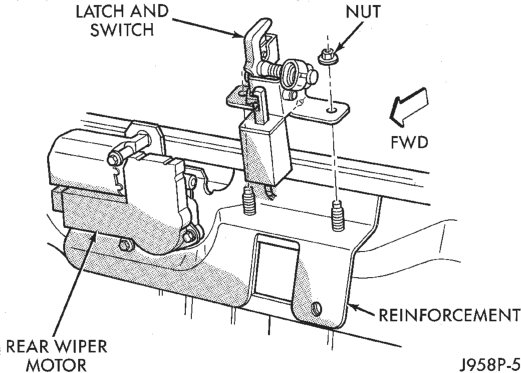
(4) Remove the two nuts securing the liftglass latch to the liftgate inner panel (Fig. 11).
(5) Unplug the wiring connectors for the liftglass latch solenoid and the liftglass ajar switch.
(6) Remove the liftglass latch from the liftgate. (7) Reverse the removal procedures to install. Tighten the latch mounting nuts to 11 N·m (100 in. lbs.).
AUTO HEADLAMP AND PARK LAMP RELAYS
WARNING: ON VEHICLES EQUIPPED WITH AIR- BAGS, REFER TO GROUP 8M - PASSIVE RESTRAINT SYSTEMS BEFORE ATTEMPTING STEERING WHEEL, STEERING COLUMN, OR INSTRUMENT PANEL COMPONENT DIAGNOSIS OR SERVICE. FAILURE TO TAKE THE PROPER PRE- CAUTIONS COULD RESULT IN ACCIDENTAL AIR- BAG DEPLOYMENT AND POSSIBLE PERSONAL INJURY.
(1) Disconnect and isolate the battery negative cable.
(2) Remove the fuse access panel by unsnapping it from the right cowl side trim panel.
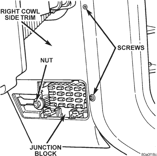
(3) Remove the nut securing the right cowl side trim to the junction block stud (Fig. 12).
(4) Remove the two screws securing the right cowl side trim to the right front door opening trim.
(5) Remove the right cowl side trim panel. (6) Remove the relay by unplugging it from the junction block.
(7) Install the relay by aligning the relay terminals with the cavities in the junction block and pushing the relay firmly into place.
(8) Reverse the remaining removal procedures to complete the installation.
HORN RELAY
(1) Disconnect and isolate the battery negative cable.
(2) Remove the cover from the Power Distribution Center (PDC) (Fig. 13).
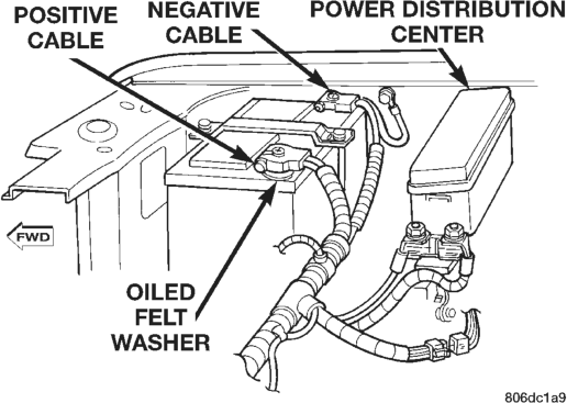
(3) Refer to the label on the PDC for horn relay identification and location.
(4) Remove the horn relay by unplugging it from the PDC.
(5) Install the horn relay by aligning the relay terminals with the cavities in the PDC and pushing the relay firmly into place.
(6) Install the PDC cover. (7) Connect the battery negative cable. (8) Test the relay operation.
SET LAMP
WARNING: ON VEHICLES EQUIPPED WITH AIR- BAGS, REFER TO GROUP 8M - PASSIVE RESTRAINT SYSTEMS BEFORE ATTEMPTING STEERING WHEEL, STEERING COLUMN, OR INSTRUMENT PANEL COMPONENT DIAGNOSIS OR SERVICE. FAILURE TO TAKE THE PROPER PRE- CAUTIONS COULD RESULT IN ACCIDENTAL AIR- BAG DEPLOYMENT AND POSSIBLE PERSONAL INJURY.
(1) Disconnect and isolate the battery negative cable.
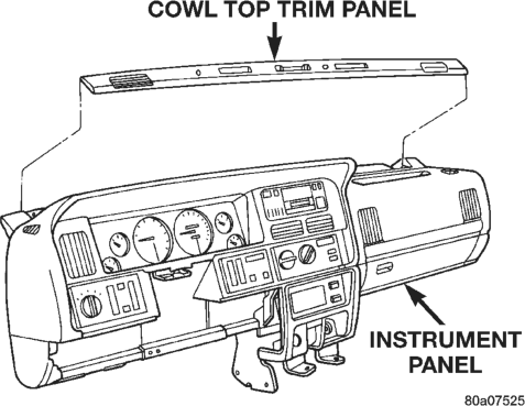
(2) Using a wide flat-bladed tool such as a trim stick, pry the cowl top trim panel off of the instrument panel top pad (Fig. 14).
(3) Pull the panel up far enough to unplug the wiring connector for the solar sensor, or to remove the solar sensor from the cowl top trim between the right and center defroster outlets, if so equipped.
(4) Remove the cowl top trim panel from the vehicle.
(5) Remove the auto headlamp light sensor/vehicle theft security system set lamp mounting screw near the left defroster duct outlet.
(6) Pull the lamp up far enough to unplug the wire harness connector and remove the lamp.
(7) Reverse the removal procedures to install.