Turn Signal and Hazard Warning Systems — 1996 Jeep Grand Cherokee ZJ Service Manual
Pages 383–387 · 5 pages · 1 words repaired
The combination flasher cannot be repaired and, if faulty, it must be replaced. Also, because of the combination flasher’s active elements, it cannot be tested with conventional automotive electrical test equipment. If the flasher is believed to be faulty, test the turn signal and hazard warning system circuits as described in this group. Then, replace the combination flasher with a known good unit to confirm system operation.
MULTI-FUNCTION SWITCH
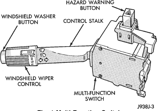
The multi-function switch assembly is mounted to the left side of the steering column (Fig. 1). This switch contains circuitry for the following functions:
• Turn signals • Hazard warning • Headlamp beam selection • Headlamp optical horn • Windshield wipers • Windshield washers. The information contained in this group addresses only the switch functions for the turn signal and hazard warning circuits. For information relative to the other switch functions, refer to the appropriate group. However, the multi-function switch cannot be repaired. If any function of the switch is faulty, the entire switch assembly must be replaced.
TURN SIGNAL INDICATOR LAMPS
The turn signal indicator lamps are located in the instrument cluster. They flash with the exterior turn signal lamps to give the driver a visual indication that a turn signal or the hazard warning system is operating. For diagnosis and service of this component, refer to Group 8E - Instrument Panel Systems.
VEHICLE INFORMATION CENTER
Models equipped with an optional Vehicle Information Center (VIC) have a “turn signal on” warning feature. The VIC module monitors the combination flasher’s turn signal circuit. The VIC module will display the message, Turn Signal On, and send a chime request signal to the Body Control Module (BCM) on the Chrysler Collision Detection (CCD) data bus for a single chime tone, if a turn signal remains activated for more than approximately one-half mile of driving.
Refer to Group 8E - Instrument Panel Systems for diagnosis and service of the VIC module. Refer to the appropriate Body Diagnostic Procedures Manual for diagnosis and service of the BCM or the CCD bus.
TURN SIGNAL LAMPS
The exterior lamps in the turn signal and hazard warning circuits include the front park/turn signal, the front side marker, and the rear tail/stop/turn signal. For diagnosis and service of these lamps, refer to Group 8L - Lamps.
DIAGNOSIS AND TESTING
INTRODUCTION
When diagnosing the turn signal or hazard warning circuits, remember that high generator output can burn out bulbs rapidly and repeatedly. If this is a problem on the vehicle being diagnosed, refer to Group 8C - Charging System for further diagnosis.
WARNING: ON VEHICLES EQUIPPED WITH AIRBAGS, REFER TO GROUP 8M - PASSIVE RESTRAINT SYS- TEMS BEFORE ATTEMPTING STEERING WHEEL, STEERING COLUMN, OR INSTRUMENT PANEL COM- PONENT DIAGNOSIS OR SERVICE. FAILURE TO TAKE THE PROPER PRECAUTIONS COULD RESULT IN ACCIDENTAL AIRBAG DEPLOYMENT AND POSSIBLE PERSONAL INJURY.
TURN SIGNAL/HAZARD WARNING SYSTEM
WARNING: ON VEHICLES EQUIPPED WITH AIRBAGS, REFER TO GROUP 8M - PASSIVE RESTRAINT SYS- TEMS BEFORE ATTEMPTING STEERING WHEEL, STEERING COLUMN, OR INSTRUMENT PANEL COM- PONENT DIAGNOSIS OR SERVICE. FAILURE TO TAKE THE PROPER PRECAUTIONS COULD RESULT IN ACCIDENTAL AIRBAG DEPLOYMENT AND POSSIBLE PERSONAL INJURY.
(1) Turn the ignition switch to the On position. Actuate the turn signal lever or hazard warning button. Observe the turn indicator lamp(s) in the instrument cluster. If the flash rate is very high, check for a turn signal bulb that is not lit. Replace that bulb or repair the circuits to that lamp, as required. Test the operation of the system again. If the turn indicator(s) fail to light, go to Step 2.
(2) Remove and inspect the turn signal fuse in the junction block, or the hazard warning fuse in the Power Distribution Center (PDC). Replace the faulty fuse(s), if required, and go to Step 3.
(3) Remove the combination flasher from the junction block and replace it with a known good unit. Test the operation of the turn signal and hazard warning systems. If OK, discard the faulty combination flasher. If not OK, remove the test flasher and go to Step 4.
(4) With the ignition switch in the On position, check for battery voltage at the fused ignition switch output circuit cavity for the flasher in the junction block. If OK, go to Step 5. If not OK, repair the open circuit to the ignition switch as required.
(5) With the ignition switch in the Off position, check for battery voltage at the fused B(+) circuit cavity for the flasher in the junction block. If OK, go to Step 6. If not OK, repair the open circuit to the PDC as required.
(6) With the ignition switch in the Off position, check for continuity between the ground circuit cavity for the flasher in the junction block and a good ground. There should be continuity. If OK, go to Step 7. If not OK, repair the circuit to ground as required. (7) Disconnect the multi-function switch connector as described in this group. Check for continuity between the hazard signal circuit cavities of the junction block and the multi-function switch connector.
There should be continuity. If OK, go to Step 8. If not OK, repair the open circuit as required.
(8) Check for continuity between the turn signal cavities of the junction block and the multi-function switch connector. There should be continuity. If OK, test the multi-function switch as described in this group. If not OK, repair the open circuit as required.
MULTI-FUNCTION SWITCH
Perform the diagnosis of the hazard warning and/or turn signal systems as described in this group before testing the multi-function switch. For circuit descriptions and diagrams, see 8W-52 - Turn Signals in Group 8W - Wiring Diagrams.
WARNING: ON VEHICLES EQUIPPED WITH AIRBAGS, REFER TO GROUP 8M - PASSIVE RESTRAINT SYS- TEMS BEFORE ATTEMPTING STEERING WHEEL, STEERING COLUMN, OR INSTRUMENT PANEL COM- PONENT DIAGNOSIS OR SERVICE. FAILURE TO TAKE THE PROPER PRECAUTIONS COULD RESULT IN ACCIDENTAL AIRBAG DEPLOYMENT AND POSSIBLE PERSONAL INJURY.
(1) Disconnect the multi-function switch connector as described in this group.
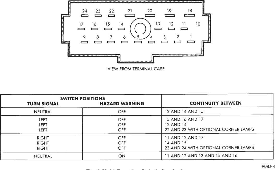
(2) Using an ohmmeter, perform the switch continuity checks at the switch terminals as shown in the chart (Fig. 2).
(3) If the switch fails any of the continuity checks, replace the faulty switch. If the switch is OK, repair the lighting circuits as required.
REMOVAL AND INSTALLATION
COMBINATION FLASHER
WARNING: ON VEHICLES EQUIPPED WITH AIR- BAGS, REFER TO GROUP 8M - PASSIVE RESTRAINT SYSTEMS BEFORE ATTEMPTING STEERING WHEEL, STEERING COLUMN, OR INSTRUMENT PANEL COMPONENT DIAGNOSIS OR SERVICE. FAILURE TO TAKE THE PROPER PRE- CAUTIONS COULD RESULT IN ACCIDENTAL AIR- BAG DEPLOYMENT AND POSSIBLE PERSONAL INJURY.
(1) Disconnect and isolate the battery negative cable.
(2) Remove the fuse access panel by unsnapping it from the right cowl side trim panel.
(3) Remove the nut securing the right cowl side trim to the junction block stud (Fig. 3).
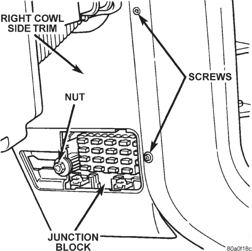
(4) Remove the two screws securing the right cowl side trim to the right front door opening trim.
(5) Remove the right cowl side trim panel. (6) Unplug the combination flasher from the junction block.
(7) To install the flasher, align the terminals with the cavities in the junction block and push the flasher firmly into place.
(8) Connect the battery negative cable. (9) Test the combination flasher operation. (10) Install the right cowl side trim panel and the fuse access panel.
MULTI-FUNCTION SWITCH
WARNING: ON VEHICLES EQUIPPED WITH AIR- BAGS, REFER TO GROUP 8M - PASSIVE RESTRAINT SYSTEMS BEFORE ATTEMPTING STEERING WHEEL, STEERING COLUMN, OR INSTRUMENT PANEL COMPONENT DIAGNOSIS OR SERVICE. FAILURE TO TAKE THE PROPER PRE- CAUTIONS COULD RESULT IN ACCIDENTAL AIR- BAG DEPLOYMENT AND POSSIBLE PERSONAL INJURY.
(1) Disconnect and isolate the battery negative cable.
(2) Remove the tilt steering column lever, if equipped.
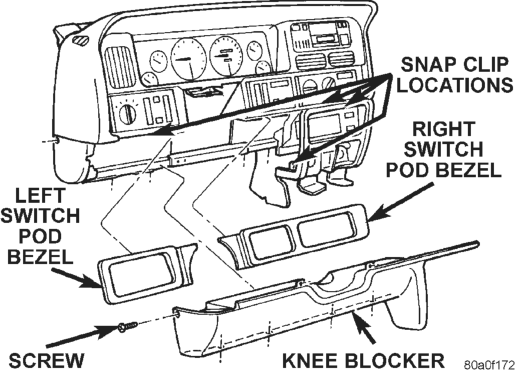
(3) Using a trim stick or other suitable wide flatbladed tool, pry gently around the edges of the switch pod bezels and remove both bezels.
(4) Remove one screw on each side of the steering column on the upper edge of the knee blocker/steering column cover (Fig. 4).
(5) Remove one screw securing the left end of the knee blocker to the instrument panel.
(6) Remove the four screws securing the lower edge of the knee blocker to the lower instrument panel reinforcement.
(7) Using a trim stick or other suitable wide flatbladed tool, gently pry the edges of the knee blocker away from the instrument panel at the locations shown (Fig. 4).
(8) Remove the knee blocker/steering column cover from the vehicle.
(9) Remove both the upper and lower shrouds from the steering column (Fig. 5).
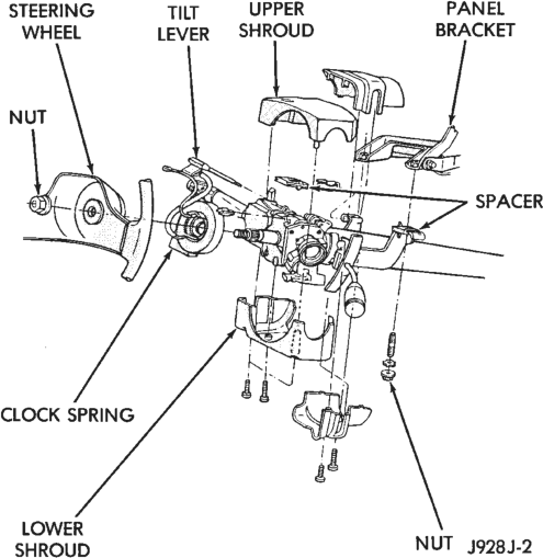
(10) Remove the lower fixed column shroud. (11) Loosen the steering column upper bracket nuts. Do not remove the nuts.
(12) Move the upper fixed column shroud to gain access to the rear of the multi-function switch (Fig. 6).
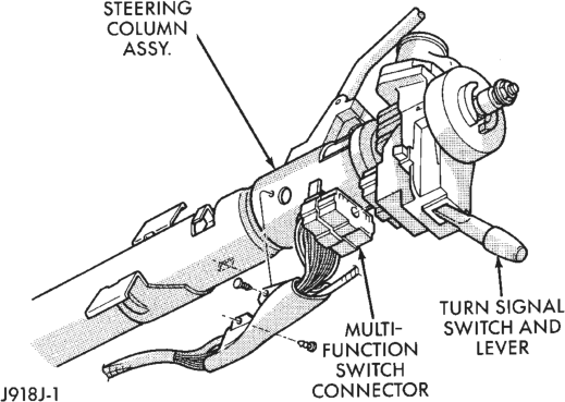
(13) Remove the multi-function switch tamper proof mounting screws (a Snap On tamper proof torx bit TTXR20B2 or equivalent is required).
(14) Gently pull the switch away from the column. Loosen the connector screw. The screw will remain in the connector.
(15) Remove the wiring connector from the multifunction switch.
(16) Reverse the removal procedures to install. Tighten the fasteners as follows:
• Multi-function switch connector screw - 1.9 N·m (17 in. lbs.)
• Multi-function switch retaining screws - 1.9 N·m (17 in. lbs.)
• Steering column upper bracket nuts - 12 N·m (110 in. lbs.).