Starting Systems — 1996 Jeep Grand Cherokee ZJ Service Manual
Pages 285–292 · 8 pages · 2 words repaired
The energized solenoid pull-in coil pulls in the solenoid plunger. The solenoid plunger pulls the shift lever in the starter. This engages the starter overrunning clutch and pinion gear with the starter ring gear on the automatic transmission torque converter (5.2L engine), or torque converter drive plate (4.0L engine).
As the solenoid plunger reaches the end of its travel, the solenoid contact disc completes the highamperage starter feed circuit and energizes the solenoid plunger hold-in coil. Current now flows between the solenoid battery terminal and the starter motor, energizing the starter.
Once the engine starts, the overrunning clutch protects the starter from damage by allowing the starter pinion gear to spin faster than the pinion shaft. When the driver releases the ignition switch to the On position, the starter relay coil is de-energized. This causes the relay contacts to open. When the relay contacts open, the starter solenoid plunger hold-in coil is de-energized.
When the solenoid plunger hold-in coil is de-energized, the solenoid plunger return spring returns the plunger to its relaxed position. This causes the contact disc to open the starter feed circuit, and the shift lever to disengage the overrunning clutch and pinion gear from the starter ring gear.
STARTER
The starter motor incorporates several features to create a reliable, efficient, compact and lightweight unit. A planetary gear system (intermediate transmission) is used between the electric motor and the pinion gear. This feature makes it possible to reduce the dimensions of the starter. At the same time, it allows higher armature rotational speed and delivers increased torque through the pinion gear to the starter ring gear on the automatic transmission torque converter or torque converter drive plate.
The use of a permanent magnet field also reduces the size and weight of the starter. The permanent magnet field consists of four high-strength permanent magnets. The magnets are aligned according to their polarity, and are permanently mounted in the starter field frame.
The starter motors for all engines are activated by a solenoid mounted to the overrunning clutch housing. However, the starter motor and solenoid are serviced only as a complete assembly. If either component fails, the entire assembly must be replaced.
CAUTION: Permanent magnet starters are highly sensitive to hammering, shocks, and external pressure. The permanent magnets may be damaged and the starter rendered unserviceable, if subjected to any of these conditions.
• The starter motor must not be clamped in a vise by the starter field frame. Doing so may damage the permanent magnets. The starter should only be clamped by the mounting flange.
• Do not connect the starter motor incorrectly when testing. Reverse polarity may damage the permanent magnets and render the starter unserviceable.
STARTER RELAY
The starter relay is a International Standards Organization (ISO) micro-relay. The terminal designations and functions are the same as a conventional ISO relay. However, the micro-relay terminal orientation (or footprint) is different, current capacity is lower, and the relay case dimensions are smaller than on the conventional ISO relay.
The starter relay is a electro-mechanical device that switches current to the pull-in coil of the starter solenoid when the ignition switch is turned to the Start position. See the Diagnosis and Testing section of this group for more information on the starter relay.
The starter relay is located in the Power Distribution Center (PDC), in the engine compartment. Refer to the PDC label for relay identification and location.
DIAGNOSIS AND TESTING
STARTING SYSTEM
For circuit descriptions and diagrams, refer to 8W-21- Starting System in Group 8W - Wiring Diagrams.
WARNING: ON VEHICLES EQUIPPED WITH AIRBAGS, REFER TO GROUP 8M - PASSIVE RESTRAINT SYS- TEMS BEFORE ATTEMPTING STEERING WHEEL, STEERING COLUMN, OR INSTRUMENT PANEL COM- PONENT DIAGNOSIS OR SERVICE. FAILURE TO TAKE THE PROPER PRECAUTIONS COULD RESULT IN ACCIDENTAL AIRBAG DEPLOYMENT AND POSSIBLE PERSONAL INJURY.
INSPECTION
Before removing any unit from the starting system for repair or diagnosis, perform the following inspections:
• Battery - Visually inspect the battery for indications of physical damage and loose or corroded cable connections. Determine the state-of-charge and cranking capacity of the battery. Charge or replace the battery, if required. Refer to Group 8A - Battery for more information.
• Ignition Switch - Visually inspect the ignition switch for indications of physical damage and loose or corroded wiring connections.
• Park/Neutral Position Switch - Visually inspect the park/neutral position switch for indications of physical damage and loose or corroded wiring connections.
• Starter Relay - Visually inspect the starter relay for indications of physical damage and loose or corroded terminal connections.
Starting System Diagnosis
CONDITION POSSIBLE CAUSE CORRECTION
STARTER FAILS TO ENGAGE.
1. Battery discharged or faulty. 2. Starting circuit wiring faulty. 3. Starter relay faulty. 4. Ignition switch faulty. 5. Park/Neutral position switch (auto trans) faulty or misadjusted. 6. Starter solenoid faulty. 7. Starter assembly faulty.
STARTER ENGAGES, FAILS TO TURN ENGINE.
1. Battery discharged or faulty. 2. Starting circuit wiring faulty. 3. Starter assembly faulty. 4. Engine seized.
STARTER ENGAGES, SPINS OUT BEFORE ENGINE STARTS.
STARTER DOES NOT DISENGAGE.
1. Starter improperly installed. 2. Starter relay faulty. 3. Ignition switch faulty. 4. Starter assembly faulty.
• Starter - Visually inspect the starter for indications of physical damage and loose or corroded wiring connections.
• Starter Solenoid - Visually inspect the starter solenoid for indications of physical damage and loose or corroded wiring connections.
• Wiring - Visually inspect the wiring for damage. Repair or replace the faulty wiring, as required.
1. Refer to Group 8A - Battery. Charge or replace battery, if required. 2. See Cold Cranking Test, in this group. Test and repair feed and/or control circuits, if required. 3. See Relay Test, in this group. Replace relay, if required. 4. See Ignition Switch Test, in this group. Replace switch, if required. 5. See Park/Neutral Position Switch Test, in this group. Replace switch, if required. 6. See Solenoid Test, in this Group. Replace starter assembly, if required. 7. If all other starting system components and circuits check OK, replace starter assembly.
1. Refer to Group 8A - Battery. Charge or replace battery, if required. 2. See Cold Cranking Test, in this group. Test and repair feed and/or control circuits, if required. 3. If all other starting system components and circuits check OK, replace starter assembly. 4. Refer to Group 9 - Engine, for diagnostic and service procedures.
1. Broken teeth on starter ring gear. 2. Starter assembly faulty. 1. Remove starter as described in this group. Inspect ring gear on torque converter or flywheel and replace, if required. 2. If all other starting system components and circuits check OK, replace starter assembly.
1. Install starter as described in this group. Tighten starter mounting hardware to correct torque specifications. 2. See Relay Test, in this group. Replace relay, if required. 3. See Ignition Switch Test, in this group. Replace switch, if required. 4. If all other starting system components and circuits check OK, replace starter assembly.
COLD CRANKING TEST
For circuit descriptions and diagrams, refer to 8W-21 - Starting System in Group 8W - Wiring Diagrams. The battery must be fully-charged and loadtested before proceeding. Refer to Group 8A - Battery for more information.
(1) Connect a suitable volt-ampere tester to the battery terminals (Fig. 1). Refer to the operating instructions provided with the tester being used.
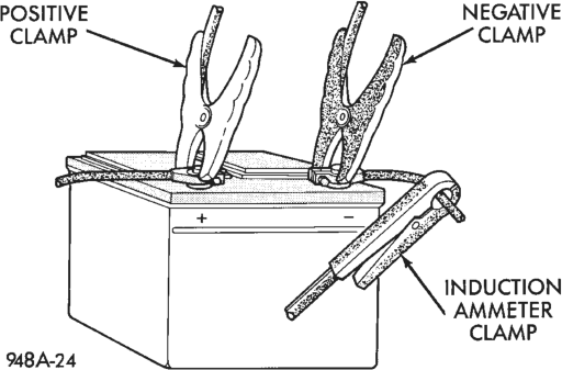
(2) Fully engage the parking brake. (3) Place the automatic transmission gearshift selector lever in the Park position.
(4) Verify that all lamps and accessories are turned off.
(5) Unplug the Automatic Shut-Down (ASD) relay to prevent the engine from starting. The ASD relay is located in the Power Distribution Center (PDC). Refer to the PDC label for ASD relay identification and location.
(6) Rotate and hold the ignition switch in the Start position. Note the cranking voltage and current (amperage) draw.
(a) If the voltage reads above 9.6 volts and the current (amperage) draw reads above specifications, see the Feed Circuit Tests in this group.
(b) If the voltage reads 12.5 volts or greater and the current (amperage) reads below specifications, see the Control Circuit Tests in this group.
NOTE: A cold engine will increase the starter current (amperage) draw reading, and reduce the battery voltage reading.
FEED CIRCUIT TESTS
The starter feed circuit tests (voltage drop method) will determine if there is excessive resistance in the high-amperage circuit. For circuit descriptions and diagrams, refer to 8W-21 - Starting System in Group 8W - Wiring Diagrams.
When performing these tests, it is important to remember that the voltage drop is giving an indication of the resistance between the two points at which the voltmeter probes are attached.
EXAMPLE: When testing the resistance of the battery positive cable, touch the voltmeter leads to the battery positive cable clamp and the cable connector at the starter solenoid. If you probe the battery positive terminal post and the cable connector at the starter solenoid, you are reading the combined voltage drop in the battery positive cable clamp-to-terminal post connection and the battery positive cable.
The following operation will require a voltmeter accurate to 1/10 (0.10) volt. Before performing the tests, be certain that the following procedures are accomplished:
• Battery is fully-charged. Refer to Group 8A - Battery for more information.
• Fully engage the parking brake. • Place the automatic transmission gearshift selector lever in the Park position.
• Unplug the Automatic Shut-Down (ASD) relay to prevent the engine from starting. The relay is located in the Power Distribution Center (PDC). Refer to the PDC label for ASD relay identification and location.
(1) Connect the positive lead of the voltmeter to the battery negative terminal post. Connect the negative lead of the voltmeter to the battery negative cable clamp (Fig. 2). Rotate and hold the ignition switch in the Start position. Observe the voltmeter. If voltage is detected, correct the poor contact between the cable clamp and the terminal post.
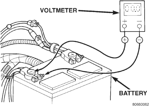
- Typical
(2) Connect the positive lead of the voltmeter to the battery positive terminal post. Connect the negative lead of the voltmeter to the battery positive cable clamp (Fig. 3). Rotate and hold the ignition switch in the Start position. Observe the voltmeter. If voltage is detected, correct the poor contact between the cable clamp and the terminal post.
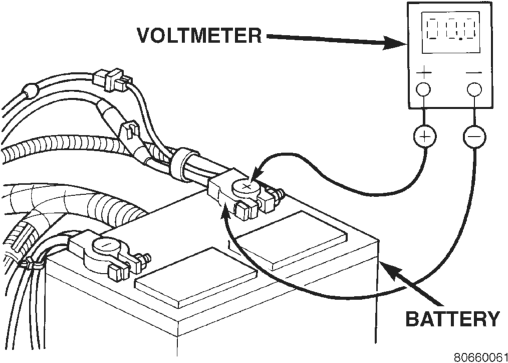
Typical
(3) Connect the voltmeter to measure between the battery positive terminal post and the starter solenoid battery terminal stud (Fig. 4). Rotate and hold the ignition switch in the Start position. Observe the voltmeter. If the reading is above 0.2 volt, clean and tighten the battery cable connection at the solenoid. Repeat the test. If the reading is still above 0.2 volt, replace the faulty battery positive cable.
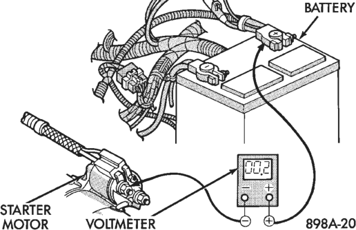
Typical
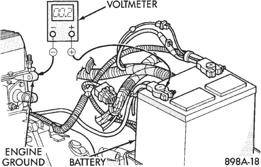
(4) Connect the voltmeter to measure between the battery negative terminal post and a good clean ground on the engine block (Fig. 5). Rotate and hold the ignition switch in the Start position. Observe the voltmeter. If the reading is above 0.2 volt, clean and tighten the battery negative cable attachment on the engine block. Repeat the test. If the reading is still above 0.2 volt, replace the faulty battery negative cable.
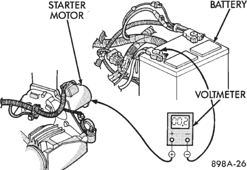
(5) Connect the positive lead of the voltmeter to the starter housing. Connect the negative lead of the voltmeter to the battery negative terminal post (Fig. 6). Rotate and hold the ignition switch in the Start position. Observe the voltmeter. If the reading is above 0.2 volt, correct the poor starter to engine block ground contact.
If the resistance tests detect no feed circuit problems, remove the starter and see the Solenoid Test in this group.
CONTROL CIRCUIT TESTS
For circuit descriptions and diagrams, refer to 8W-21 - Starting System in Group 8W - Wiring Diagrams. The starter control circuit consists of:
• Battery • Starter relay • Starter solenoid • Ignition switch • Park/neutral position switch • Wiring harness and connections. Test procedures for these components should be performed in the order in which they are listed, as follows:
SOLENOID TEST
Remove the starter as described in this group. Then proceed as follows:
(1) Disconnect the wire from the solenoid field coil terminal.
(2) Check for continuity between the solenoid terminal and field coil terminal with a continuity tester (Fig. 7). There should be continuity. If OK, go to Step 3. If not OK, replace the faulty starter assembly.
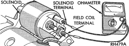
and Field Coil Terminal
(3) Check for continuity between the solenoid terminal and the solenoid case (Fig. 8). There should be continuity. If OK, go to Step 4. If not OK, replace the faulty starter assembly.
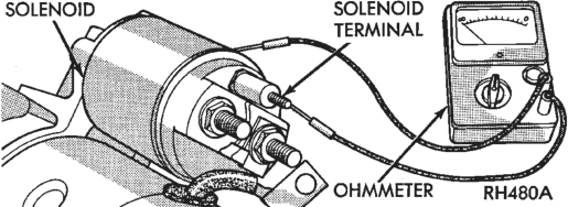
and Solenoid Case
(4) Connect the solenoid field coil wire to the field coil terminal.
(5) Install the starter as described in this group.
RELAY TEST
The starter relay is located in the Power Distribution Center (PDC) in the engine compartment. Refer to the PDC label for relay identification and location.
Remove the starter relay from the PDC as described in this group to perform the following tests:
(1) A relay in the de-energized position should have continuity between terminals 87A and 30, and no continuity between terminals 87 and 30. If OK, go to Step 2. If not OK, replace the faulty relay.
(2) Resistance between terminals 85 and 86 (electromagnet) should be 7565 ohms. If OK, go to Step 3. If not OK, replace the faulty relay. (3) Connect a battery to terminals 85 and 86. There should now be continuity between terminals 30 and 87, and no continuity between terminals 87A and 30. If OK, see the Relay Circuit Test in this group. If not OK, replace the faulty relay.
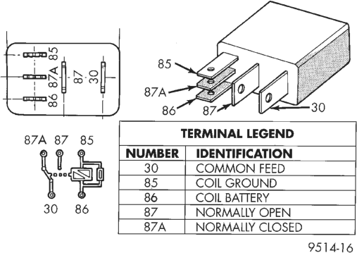
Starter Relay
RELAY CIRCUIT TEST
(1) The relay common feed terminal cavity (30) is connected to battery voltage and should be hot at all times. If OK, go to Step 2. If not OK, repair the open circuit to the PDC fuse as required.
(2) The relay normally closed terminal (87A) is connected to terminal 30 in the de-energized position, but is not used for this application. Go to Step 3.
(3) The relay normally open terminal (87) is connected to the common feed terminal (30) in the energized position. This terminal supplies battery voltage to the starter solenoid field coils. There should be continuity between the cavity for relay terminal 87 and the starter solenoid terminal at all times. If OK, go to Step 4. If not OK, repair the open circuit to the starter solenoid as required.
(4) The coil battery terminal (86) is connected to the electromagnet in the relay. It is energized when the ignition switch is held in the Start position. Check for battery voltage at the cavity for relay terminal 86 with the ignition switch in the Start position, and no voltage when the ignition switch is released to the On position. If OK, go to Step 5. If not OK, check for an open or short circuit to the ignition switch and repair, if required. If the circuit to the ignition switch is OK, see the Ignition Switch Test in this group.
(5) The coil ground terminal (85) is connected to the electromagnet in the relay. It is grounded through the park/neutral position switch only when the gearshift selector lever is in the Park or Neutral positions. Check for continuity to ground at the cavity for relay terminal 85. If not OK, check for an open or short circuit to the park/neutral position switch and repair, if required. If the circuit is OK, see the Park/Neutral Position Switch Test in this group.
PARK/NEUTRAL POSITION SWITCH TEST
(1) Place the transmission gear selector lever in the Park position.
(2) Disconnect and isolate the battery negative cable.
(3) Raise and support the vehicle. (4) Disconnect the park/neutral position switch harness connector.
(5) Check for continuity between the center switch terminal and a good chassis ground. There should be continuity. If OK, go to Step 6. If not OK, replace the faulty switch.
(6) Move the transmission gear selector to the Reverse position and check for continuity between the center switch terminal and a good chassis ground. There should be no continuity. If not OK, replace the faulty switch.
IGNITION SWITCH TEST
WARNING: ON VEHICLES EQUIPPED WITH AIR- BAGS, REFER TO GROUP 8M - PASSIVE RESTRAINT SYSTEMS BEFORE ATTEMPTING STEERING WHEEL, STEERING COLUMN, OR INSTRUMENT PANEL COMPONENT DIAGNOSIS OR SERVICE. FAILURE TO TAKE THE PROPER PRE- CAUTIONS COULD RESULT IN ACCIDENTAL AIR- BAG DEPLOYMENT AND POSSIBLE PERSONAL INJURY.
(1) Disconnect and isolate the battery negative cable.
(2) Remove the steering column shrouds and disconnect the ignition switch harness connector. Refer to Group 8D - Ignition Systems for the procedures.
(3) With the ignition switch in the On position, check for continuity between the ignition switch terminals 1 and 7. These are the terminals at each end of the switch connector. There should be no continuity. If OK, go to Step 4. If not OK, replace the faulty switch.
(4) With the ignition switch held in the Start position, check for continuity between the ignition switch terminals 1 and 7 again. There should now be continuity. If not OK, replace the faulty switch.
REMOVAL AND INSTALLATION
STARTER
4.0L ENGINE (1) Disconnect and isolate the battery negative cable.
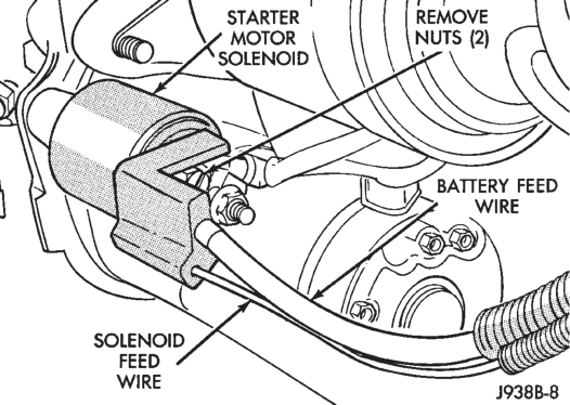
(2) Raise and support the vehicle. (3) Disconnect the battery cable and solenoid feed wire from the starter solenoid (Fig. 9).
(4) Remove the front starter mounting bolt and oil cooler line bracket (Fig. 10).
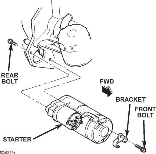
(5) Remove the rear starter mounting bolt and lower the starter.
(6) Reverse the removal procedures to install. Tighten the starter hardware as follows:
• Upper mounting bolt - 55 N·m (40 ft. lbs.) • Lower mounting bolt - 41 N·m (30 ft. lbs.) • Solenoid battery cable nut - 10 N·m (90 in. lbs.) • Solenoid terminal nut - 6 N·m (55 in. lbs.).
5.2L ENGINE (1) Disconnect and isolate the battery negative cable.
(2) Raise and support the vehicle.
(3) Disconnect the battery cable and solenoid feed wire from the starter solenoid (Fig. 9).
(4) Remove the lower starter mounting bolt and exhaust brace (Fig. 11).
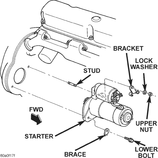
(5) Remove the upper starter mounting nut, lock washer, and oil cooler line bracket.
(6) Move the starter towards the front of the vehicle until the starter gear housing nose clears the bellhousing. Then tilt the starter nose downwards past the exhaust pipe.
(7) Reverse the removal procedures to install. Tighten the starter hardware as follows:
• Lower mounting bolt - 68 N·m (50 ft. lbs.) • Upper mounting nut - 68 N·m (50 ft. lbs.) • Solenoid battery cable nut - 10 N·m (90 in. lbs.) • Solenoid terminal nut - 6 N·m (55 in. lbs.).
STARTER RELAY
(1) Disconnect and isolate the battery negative cable.
(2) Remove the cover from the Power Distribution Center (PDC) (Fig. 12).
(3) Refer to the label on the PDC for starter relay identification and location.
(4) Remove the starter relay by unplugging it from the PDC.
(5) Install the starter relay by aligning the relay terminals with the cavities in the PDC and pushing the relay firmly into place.
(6) Install the PDC cover. (7) Connect the battery negative cable.

(8) Test the relay operation.
SPECIFICATIONS
STARTING SYSTEM
Starter and Solenoid
Manufacturer Mitsubishi Mitsubishi
Engine Application 4.0L 5.2L
Power Rating 1.4 Kilowatt 1.4 Kilowatt
Voltage 12 Volts 12 Volts
Number of Fields 4 4
Number of Poles 4 4
Number of Brushes
4 4
Drive Type Planetary
Planetary
Gear Reduction
Gear Reduction
Free Running Test Voltage
11.2 Volts 11.2 Volts
Free Running Test Maximum Amperage Draw
80 Amperes 80 Amperes
Free Running Test Minimum Speed
2500 rpm 2500 rpm
Solenoid Closing Maximum Voltage
7.8 Volts 7.8 Volts
*Cranking Amperage Draw Test
160 Amperes 160 Amperes
*Test at operating temperature. Cold engine, tight (new) engine, or heavy oil will increase starter amperage draw.