Passive Restraint Systems — 1996 Jeep Grand Cherokee ZJ Service Manual
Pages 420–429 · 10 pages · 3 words repaired
DESCRIPTION AND OPERATION
AIRBAG MODULE
DRIVER’S SIDE
The airbag module protective cover is the most visible part of the driver’s side airbag system. The module is mounted directly to the steering wheel. Under the airbag module cover, the airbag cushion and its supporting components are contained. The airbag module contains a housing to which the cushion and inflator are attached and sealed. The airbag module cannot be repaired, and must be replaced if deployed or in any way damaged.
The inflator assembly is mounted to the back of the module. The inflator seals the hole in the airbag cushion so it can discharge the gas it produces directly into the cushion when supplied with the proper electrical signal. The protective cover is fitted to the front of the airbag module and forms a decorative cover in the center of the steering wheel. Upon airbag deployment, this cover will split horizontally.
PASSENGER’S SIDE
The instrument panel top pad is the most visible part of the passenger’s side airbag system. Under the instrument panel top pad, the airbag cushion and its supporting components are contained. The airbag module contains a housing to which the cushion and inflator are attached and sealed. The airbag module cannot be repaired, and must be replaced if deployed or in any way damaged.
The inflator assembly is mounted to the back of the airbag module. The inflator seals the hole in the airbag cushion so it can discharge the gas it produces directly into the cushion when supplied with the proper electrical signal. The instrument panel top pad above the glove box opening has a door and predetermined break-out lines concealed beneath its decorative cover. Upon airbag deployment, the top pad will split at the break-out lines and the door will pivot out of the way. The instrument panel top pad must be replaced following an airbag deployment.
The airbag module is mounted to two brackets beneath the instrument panel top pad and above the glove box opening. The airbag front mounting bracket (closest to the dash panel) is welded to the instrument panel armature. The airbag rear mounting bracket (closest to the passenger) is bolted to the instrument panel armature. Following an airbag deployment, the airbag rear mounting bracket must be replaced. If the airbag front mounting bracket is damaged, the instrument panel armature assembly must be replaced.
STORAGE
An airbag module must be stored in its original, special container until used for service. Also, it must be stored in a clean, dry environment; away from sources of extreme heat, sparks, and high electrical energy. Always place or store an airbag module on a surface with its trim cover or airbag side facing up, to minimize movement in case of an accidental deployment.
IMPACT SENSORS
The impact sensors provide verification of the direction and severity of the impact. Three sensors are used. One is called a safing sensor. It is located inside the Airbag Control Module (ACM), which is mounted under the center floor console next to the parking brake mounting bracket. The other two sensors are mounted on the radiator side closure panel extensions, on the left and right sides of the vehicle behind the grille opening reinforcement panel.
The impact sensors are threshold sensitive switches that complete an electrical circuit when an impact provides a sufficient deceleration force to close the switch. The sensors are calibrated for the specific vehicle, and react to the severity and direction of the impact.
The impact sensors are available for service replacement. The safing sensor is only serviced as part of the ACM.
CLOCKSPRING
The clockspring is mounted on the steering column behind the steering wheel. This assembly consists of a plastic housing which contains a flat, ribbon-like electrically conductive tape that winds and unwinds with the steering wheel rotation.
The clockspring is used to maintain a continuous electrical circuit between the wiring harness and the driver’s side airbag module, the horn switch, the speed control switches, and the remote radio switches. There are separate versions of the clockspring for models equipped with or without the optional speed proportional steering. Refer to Group 19 - Steering for more information. The clockspring cannot be repaired and, if damaged or faulty, it must be replaced. The clockspring must be replaced following an airbag system deployment.
AIRBAG CONTROL MODULE
The Airbag Control Module (ACM) contains the safing sensor, and a microprocessor that monitors the airbag system to determine its readiness. The ACM contains On-Board Diagnostics (OBD), and will send an airbag lamp-on message to the instrument cluster on the Chrysler Collision Detection (CCD) data bus to light the airbag indicator lamp in the instrument cluster when a monitored airbag system fault occurs.
The ACM also contains an energy-storage capacitor. This capacitor stores enough electrical energy to deploy the airbags for up to one second following a battery disconnect or failure during an impact. The purpose of the capacitor is to provide airbag system protection in a severe secondary impact, if the initial impact has damaged or disconnected the battery, but was not severe enough to deploy the airbags.
The ACM cannot be repaired and, if damaged or faulty, it must be replaced.
DIAGNOSIS AND TESTING
AIRBAG SYSTEM
A DRB scan tool is required for diagnosis of the airbag system. Refer to the proper Body Diagnostic Procedures Manual for more information.
(1) Disconnect and isolate the battery negative cable. If the airbag system is undeployed, wait two minutes for the system capacitor to discharge before further service.
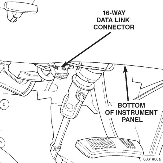
(2) Connect the DRB scan tool to the 16-way data link connector. The connector is located under the lower left corner of the instrument panel behind the steering column cover/knee blocker (Fig. 1).
(3) Turn the ignition switch to the On position. Exit the vehicle with the DRB. Use the latest version of the proper DRB cartridge.
(4) After checking that nobody is inside the vehicle, reconnect the battery negative cable.
(5) Using the DRB, read and record the active Diagnostic Trouble Code (DTC) data.
(6) Read and record any stored DTC data. (7) Refer to the proper Body Diagnostic Procedures Manual, if any DTC is found in Step 5 or Step 6.
(8) Erase the stored DTC data, if there are no active fault codes. If any problems remain, the stored DTC data will not erase.
(9) With the ignition switch still in the On position, make sure nobody is in the vehicle.
(10) From outside of the vehicle (away from the airbag modules in case of an accidental deployment) turn the ignition switch to the Off position, and then back to the On position. Observe the airbag indicator lamp in the instrument cluster. It should light for six to eight seconds - then go out. This indicates that the airbag system is functioning normally.
NOTE: If the airbag warning lamp fails to light, or lights and stays on, there is a system malfunction. Refer to the proper Body Diagnostic Procedures Manual to diagnose the problem.
SERVICE PROCEDURES
AIRBAG SYSTEM
UNDEPLOYED
At no time should any source of electricity be permitted near the inflator on the back of an airbag module. When carrying an undeployed airbag module, the trim cover or airbag side should be pointed away from the body to minimize injury in the event of accidental deployment. If the module is placed on a bench or any other surface, the trim cover or airbag side should be face up to minimize movement in the event of an accidental deployment.
In addition, the airbag system should be disarmed whenever steering wheel, steering column, or instrument panel components require diagnosis or service. Failure to observe this warning could result in accidental airbag deployment and possible personal injury. Refer to Group 8E - Instrument Panel Systems for additional service procedures on the instrument panel. Refer to Group 19 - Steering for additional service procedures on the steering wheel and steering column.
DEPLOYED
Any vehicle which is to be returned to use after an airbag system deployment, must have the airbag modules, clockspring, instrument panel top pad, and the passenger’s side airbag rear mounting bracket replaced. These are one-time components and cannot be reused. Other components are replaced as required by the extent of the damage incurred.
CLEAN-UP PROCEDURE
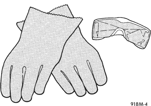
Following an airbag system deployment, the vehicle interior will contain a powdery residue. This residue is primarily sodium bicarbonate (baking soda), used as an airbag cushion lubricant. However, there will also be traces of sodium hydroxide powder, a chemical by-product of the generant used for airbag deployment. Since this powder can irritate the skin, eyes, nose, or throat, be sure to wear safety glasses, rubber gloves, and a long-sleeved shirt during cleanup (Fig. 2).
WARNING: IF YOU EXPERIENCE SKIN IRRITATION DURING CLEANUP, RUN COOL WATER OVER THE AFFECTED AREA. ALSO, IF YOU EXPERIENCE IRRITATION OF THE NOSE OR THROAT, EXIT THE VEHICLE FOR FRESH AIR UNTIL THE IRRITATION CEASES. IF IRRITATION CONTINUES, SEE A PHYSI- CIAN.
Begin by removing the airbag modules from the vehicle as described in this group.
Use a vacuum cleaner to remove any residual powder from the vehicle interior. Clean from outside the vehicle and work your way inside, so that you avoid kneeling or sitting on an uncleaned area.
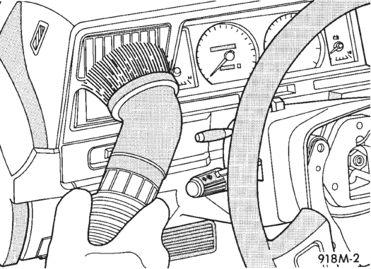
Be sure to vacuum the heater and air conditioning outlets as well (Fig. 3). Run the heater and air conditioning blower on the lowest speed setting and vacuum any powder expelled from the outlets. You may need to vacuum the interior of the vehicle a second time to recover all of the powder.
Place the deployed airbag modules in your vehicular scrap pile.
REMOVAL AND INSTALLATION
AIRBAG MODULE
WARNING: THE AIRBAG SYSTEM IS A SENSITIVE, COMPLEX ELECTRO-MECHANICAL UNIT. BEFORE ATTEMPTING TO DIAGNOSE OR SERVICE THE AIR- BAG SYSTEM OR RELATED STEERING WHEEL, STEERING COLUMN, OR INSTRUMENT PANEL COMPONENTS YOU MUST FIRST DISCONNECT AND ISOLATE THE BATTERY NEGATIVE (GROUND) CABLE. THEN WAIT TWO MINUTES FOR THE SYS- TEM CAPACITOR TO DISCHARGE BEFORE FUR- THER SYSTEM SERVICE. THIS IS THE ONLY SURE WAY TO DISABLE THE AIRBAG SYSTEM. FAILURE TO DO THIS COULD RESULT IN ACCIDENTAL AIR- BAG SYSTEM DEPLOYMENT AND POSSIBLE PER- SONAL INJURY.
• WHEN REMOVING A DEPLOYED AIRBAG MOD- ULE, RUBBER GLOVES, EYE PROTECTION, AND A LONG-SLEEVED SHIRT SHOULD BE WORN. THERE MAY BE DEPOSITS ON THE AIRBAG MODULE AND OTHER INTERIOR SURFACES. IN LARGE DOSES, THESE DEPOSITS MAY CAUSE IRRITATION TO THE SKIN AND EYES.
DRIVER’S SIDE
(1) Disconnect and isolate the battery negative cable. If the airbag module is undeployed, wait two minutes for the system capacitor to discharge before further service.
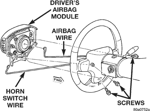
(2) Remove the three screws securing the driver’s airbag module to the steering wheel (Fig. 4).
(3) Unplug the airbag and horn switch wiring connectors and remove the airbag module from the steering wheel.
(4) If the airbag is deployed, see the procedure for replacing the clockspring in this group.
(5) When installing, connect the clockspring wiring connector to the module by pressing straight in on the connector. Tighten the airbag module mounting screws to 10.2 N·m (90 in. lbs.).
(6) Do not connect the battery negative cable at this time. See Airbag System in Diagnosis and Testing for the proper procedures.
PASSENGER’S SIDE
(1) Disconnect and isolate the battery negative cable. If the airbag module is undeployed, wait two minutes for the system capacitor to discharge before further service.
(2) Remove the instrument panel top pad. Refer to Group 8E - Instrument Panel Systems for the procedures.
(3) Remove the two screws securing the airbag module to the front airbag mounting bracket (Fig. 5).
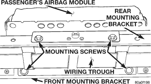
(4) Remove the two screws securing the airbag module to the rear airbag mounting bracket.
(5) Unplug the airbag wiring connector and remove the airbag module from the instrument panel.
(6) If the airbag is deployed, see the procedure for replacing the rear airbag mounting bracket in this group.
(7) When installing, be certain the airbag wiring connector halves are fully engaged. Tighten the airbag module mounting screws to 11.75 N·m (105 in. lbs.).
NOTE: If the airbag module mounting screws cannot be tightened to the specified torque value, replace the screws with the over-sized screws specified in the Mopar Parts Catalog.
(8) Reverse the remaining removal procedures to complete the installation, but do not connect the battery negative cable at this time. See Airbag System in Diagnosis and Testing for the proper procedures.
DRIVER’S AIRBAG TRIM COVER AND HORN SWITCH
WARNING: THE AIRBAG SYSTEM IS A SENSITIVE, COMPLEX ELECTRO-MECHANICAL UNIT. BEFORE ATTEMPTING TO DIAGNOSE OR SERVICE THE AIR- BAG SYSTEM OR RELATED STEERING WHEEL, STEERING COLUMN, OR INSTRUMENT PANEL COMPONENTS YOU MUST FIRST DISCONNECT AND ISOLATE THE BATTERY NEGATIVE (GROUND) CABLE. THEN WAIT TWO MINUTES FOR THE SYS- TEM CAPACITOR TO DISCHARGE BEFORE FUR- THER SYSTEM SERVICE. THIS IS THE ONLY SURE WAY TO DISABLE THE AIRBAG SYSTEM. FAILURE TO DO THIS COULD RESULT IN ACCIDENTAL AIR- BAG SYSTEM DEPLOYMENT AND POSSIBLE PER- SONAL INJURY.
• THE HORN SWITCH IS INTEGRAL TO THE AIR- BAG MODULE TRIM COVER. SERVICE OF THIS COMPONENT SHOULD BE PERFORMED ONLY BY CHRYSLER-TRAINED AND AUTHORIZED DEALER SERVICE TECHNICIANS. FAILURE TO TAKE THE PROPER PRECAUTIONS OR TO FOLLOW THE PROPER PROCEDURES COULD RESULT IN ACCI- DENTAL, INCOMPLETE, OR IMPROPER AIRBAG DEPLOYMENT AND POSSIBLE PERSONAL INJURY.
(1) Disconnect and isolate the battery negative cable. If the airbag module is undeployed, wait two minutes for the system capacitor to discharge before further service.
(2) Remove the driver’s airbag module as described in this group.
(3) Remove the two plastic horn switch feed wire retainers from the studs on the airbag housing (Fig. 6). (4) Disconnect the horn switch ground wire from the airbag module lower trim cover retainer.
(5) Remove the four nuts securing the upper and lower trim cover retainers to the studs on the airbag housing (Fig. 7).
(6) Remove the upper and lower trim cover retainers from the airbag housing studs.
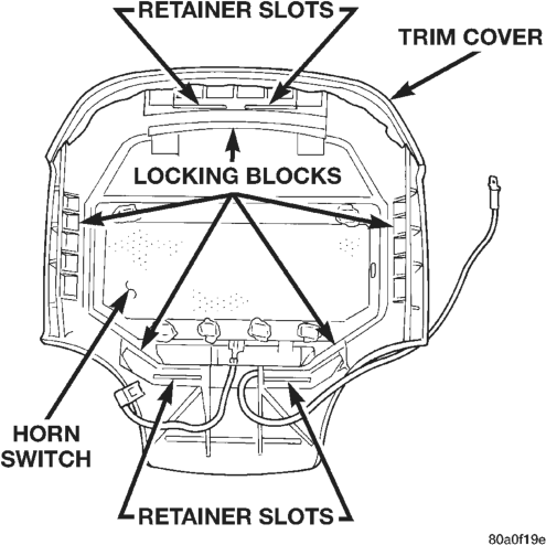
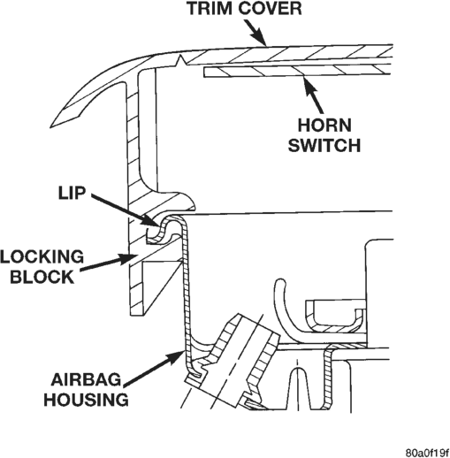
(7) Release the five trim cover locking blocks from the lip around the outside edge of the airbag housing and remove the housing from the cover (Fig. 8).
(8) When installing the trim cover/horn switch, be certain that the locking blocks are fully engaged on the lip of the airbag housing (Fig. 9).
(9) When installing the upper and lower trim cover retainers, be certain that the tabs on each retainer are engaged in the retainer slots of the trim cover (Fig. 8). Tighten the retainer nuts to 10 N·m (90 in. lbs.).
(10) Reverse the remaining removal procedures to complete the installation, but do not connect the battery negative cable at this time. See Airbag System in Diagnosis and Testing for the proper procedures.
PASSENGER’S AIRBAG REAR MOUNTING BRACKET
(1) Remove the passenger’s side airbag module as described in this group.
(2) Remove the screws securing the instrument panel wiring trough to the airbag rear mounting bracket.
(3) Remove the heater-A/C controls from the instrument panel. Refer to Group 24 - Heating and Air Conditioning for the procedures.
(4) Reaching through the heater-A/C control opening in the instrument panel, remove the two bolts securing the left end of the bracket to the instrument panel armature (Fig. 10).
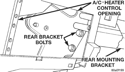
(5) Remove the two bolts securing the right end of the bracket from the right end of the instrument panel armature (Fig. 11).
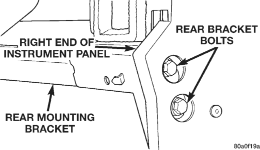
(6) Remove the rear mounting bracket through the lower opening of the instrument panel armature, right end first.
(7) Reverse the removal procedures to install. Tighten the mounting bolts to 11.75 N·m (105 in. lbs.).
IMPACT SENSORS
The impact sensors are located on the radiator side closure panel extensions behind the grille opening reinforcement.
(1) Disconnect and isolate the battery negative cable. If the airbag module is undeployed, wait two minutes for the system capacitor to discharge before further service.
(2) Remove the screws securing the grille to the grille opening reinforcement (Fig. 12).
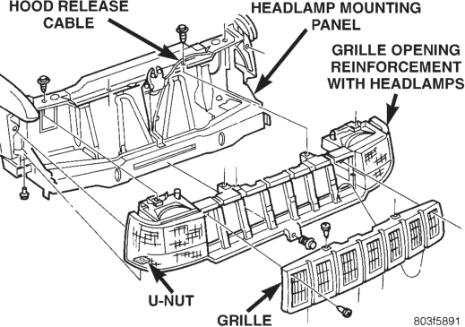
(3) Remove the grille from the grille opening reinforcement.
(4) Remove the turn signal, side marker, and head lamps. Refer to Group 8L - Lamps for the procedures.
(5) Remove the six push-in retainers securing the front fascia to the front crossmember (Fig. 13).
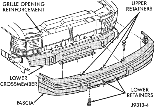
(6) Remove the three retainers at the front of each front wheel opening.
(7) Slide the fascia off of the retainers on each end of the front crossmember and remove the fascia.
(8) Remove the three screws securing each impact sensor to the front wheelhouse extensions (Fig. 14).
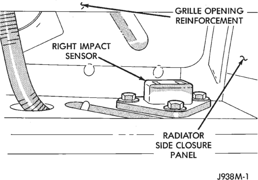
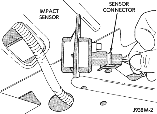
(9) Unplug the wiring connector from the impact sensor and remove (Fig. 15).
(10) Reverse the removal procedures to install. Tighten the sensor mounting screws to 3.5 - 4.5 N·m (30 - 40 in. lbs.).
(11) Do not connect the battery negative cable at this time. See Airbag System in Diagnosis and Testing for the proper procedures.
AIRBAG CONTROL MODULE
WARNING: THE AIRBAG CONTROL MODULE CON- TAINS ONE OF THE IMPACT SENSORS, WHICH ENABLE THE SYSTEM TO DEPLOY THE AIRBAG. TO AVOID ACCIDENTAL DEPLOYMENT, NEVER CONNECT THE AIRBAG CONTROL MODULE ELEC- TRICALLY TO THE SYSTEM UNLESS IT IS BOLTED TO THE VEHICLE. NEVER STRIKE OR KICK THE AIRBAG CONTROL MODULE. BEFORE BEGINNING
ANY AIRBAG SYSTEM REMOVAL OR INSTALLA- TION PROCEDURES, DISCONNECT AND ISOLATE THE BATTERY NEGATIVE (GROUND) CABLE FROM THE VEHICLE BATTERY. THEN WAIT TWO MINUTES FOR THE SYSTEM CAPACITOR TO DISCHARGE BEFORE FURTHER SYSTEM SERVICE. THIS IS THE ONLY SURE WAY TO DISABLE THE AIRBAG SYS- TEM. FAILURE TO DO THIS COULD RESULT IN ACCIDENTAL AIRBAG DEPLOYMENT, AND POSSI- BLE PERSONAL INJURY.
(1) Disconnect and isolate the battery negative cable. If the airbag is undeployed, wait two minutes for the system capacitor to discharge before further service.
(2) Pull the transmission shift lever handle straight up firmly and quickly to remove the handle.
(3) Remove the transmission and transfer case shift indicator bezels by prying between the edge of the bezels and the floor console with a trim stick or other suitable wide flat-bladed tool (Fig. 16). Then disconnect the lamp sockets from the bezels.
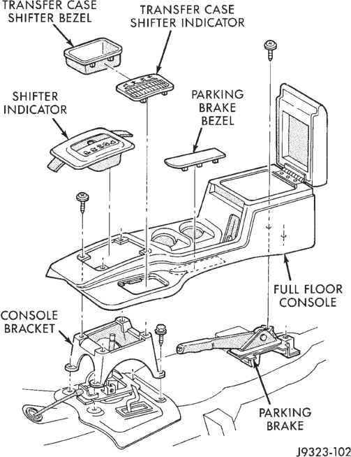
(4) Remove the screws securing the floor console to the console and parking brake lever mounting brackets.
(5) Remove the floor console from the floor pan transmission tunnel.
(6) Unplug the two electrical connectors from the airbag control module.
(7) Remove the four screws securing the airbag control module mounting bracket to the floor pan transmission tunnel (Fig. 17).
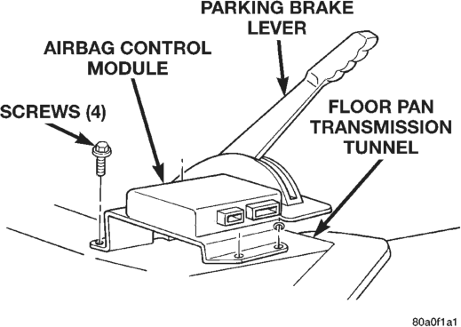
(8) Remove the airbag control module. (9) When installing the airbag control module, position the unit with the arrow on the module housing pointing forward.
(10) Attach the airbag control module to the floor pan transmission tunnel with the four screws. Tighten the mounting screws to 10.7 N·m (95 in. lbs.).
(11) Connect the wiring to the airbag control module, making sure both of the connectors are fullyseated and their locking tabs are engaged.
(12) Reverse the remaining removal procedures to complete the installation.
(13) Do not connect the battery negative cable at this time. See Airbag System in Diagnosis and Testing for the proper procedures.
CLOCKSPRING
WARNING: THE AIRBAG SYSTEM IS A SENSITIVE, COMPLEX ELECTRO-MECHANICAL UNIT. BEFORE ATTEMPTING TO DIAGNOSE OR SERVICE THE AIR- BAG SYSTEM OR RELATED STEERING WHEEL, STEERING COLUMN, OR INSTRUMENT PANEL COMPONENTS YOU MUST FIRST DISCONNECT AND ISOLATE THE BATTERY NEGATIVE (GROUND) CABLE. THEN WAIT TWO MINUTES FOR THE SYS- TEM CAPACITOR TO DISCHARGE BEFORE FUR- THER SYSTEM SERVICE. THIS IS THE ONLY SURE WAY TO DISABLE THE AIRBAG SYSTEM. FAILURE TO DO THIS COULD RESULT IN ACCIDENTAL AIR- BAG SYSTEM DEPLOYMENT AND POSSIBLE PER- SONAL INJURY.
(1) Turn the steering wheel until the front wheels are in the straight-ahead position before starting the repair.
(2) Disconnect and isolate the battery negative cable. If the airbag system is undeployed, wait two minutes for the system capacitor to discharge before further service.
(3) Remove the airbag module as described in this group.
(4) Unplug the wiring for the speed control and remote radio switches, if equipped.
(5) Remove the steering wheel with a steering wheel puller (Special Tool C-3428B).
(6) Remove the upper and lower steering column shrouds to gain access to the clockspring wiring (Fig. 18).
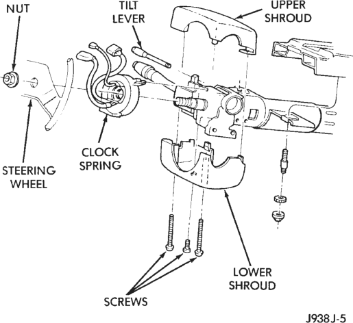
(7) Disconnect the two-way connector between the clockspring and the instrument panel wiring harness at the base of the steering column.
(8) To remove, lift the locating fingers of the clockspring assembly from the steering column as necessary. The clockspring cannot be repaired. It must be replaced if faulty, or if the airbag system has been deployed.
(9) When installing, snap the clockspring onto the steering column. If the clockspring is not properly positioned, see Clockspring Centering in this group before installing the steering wheel.
(10) Connect the clockspring wiring to the instrument panel wiring harness. Be certain that the wiring locator clips are properly seated on the outside of the wiring trough and that the locking tabs are engaged.
(11) Re-install the steering column shrouds. Be certain that the airbag wire is inside the shrouds.
(12) The front wheels should still be in the straight-ahead position. Install the steering wheel being certain to fit the flats on the hub of the steering wheel with the formations on the inside of the clockspring. Pull the wiring through the upper and lower holes in the steering wheel hub. Tighten the steering wheel nut to 61 N·m (45 ft. lbs.). Be certain not to pinch the wiring between the steering wheel and the nut.
(13) Connect the speed control and remote radio switch wiring. Connect the horn switch wire, then the airbag wire to the airbag module.
(14) Install the airbag module and tighten the screws to 10.2 N·m (90 in. lbs.).
(15) Do not connect the battery negative cable at this time. See Airbag System in Diagnosis and Testing for the proper procedures.
ADJUSTMENTS
CLOCKSPRING CENTERING
If the rotating tape within the clockspring is not positioned properly in relation to the steering wheel and the front wheels, the clockspring may fail during use. The clockspring must be centered if it is not known to be properly positioned, or if the front wheels were moved from the straight-ahead position with the clockspring removed during any service procedure.
WARNING: THE AIRBAG SYSTEM IS A SENSITIVE, COMPLEX ELECTRO-MECHANICAL UNIT. BEFORE ATTEMPTING TO DIAGNOSE OR SERVICE THE AIR- BAG SYSTEM OR RELATED STEERING WHEEL, STEERING COLUMN, OR INSTRUMENT PANEL COMPONENTS YOU MUST FIRST DISCONNECT AND ISOLATE THE BATTERY NEGATIVE (GROUND) CABLE. THEN WAIT TWO MINUTES FOR THE SYS- TEM CAPACITOR TO DISCHARGE BEFORE FUR- THER SYSTEM SERVICE. THIS IS THE ONLY SURE WAY TO DISABLE THE AIRBAG SYSTEM. FAILURE TO DO THIS COULD RESULT IN ACCIDENTAL AIR- BAG SYSTEM DEPLOYMENT AND POSSIBLE PER- SONAL INJURY.
(1) Turn the steering wheel until the front wheels are in the straight-ahead position before starting the centering procedure.
(2) Disconnect and isolate the battery negative cable. If the airbag system is undeployed, wait two minutes for the system capacitor to discharge before further service.
(3) Remove the airbag module as described in this group.
(4) Unplug the wiring for the speed control and remote radio switches, if so equipped.
(5) Remove the steering wheel with a steering wheel puller (Special Tool C-3428B).
(6) Depress the two plastic auto-locking tabs (Fig. 19).
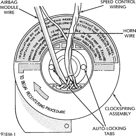
(7) Keeping the locking mechanism disengaged, rotate the clockspring rotor clockwise to the end of its travel. Do not apply excessive torque.
(8) From the end of the clockwise travel, rotate the rotor two and one-half turns counterclockwise. The horn wire should end up at the top, and the airbag wire at the bottom.
(9) The front wheels should still be in the straightahead position. Install the steering wheel being certain to fit the flats on the hub of the steering wheel with the formations on the inside of the clockspring. Pull the wiring through the upper and lower holes in the steering wheel hub. Tighten the steering wheel nut to 61 N·m (45 ft. lbs.). Be certain not to pinch the wiring between the steering wheel and the nut.
(10) Connect the speed control and remote radio switch wiring. Connect the horn switch wire, then the airbag wire to the airbag module.
(11) Install the airbag module and tighten the screws to 10.2 N·m (90 in. lbs.).
(12) Do not connect the battery negative cable at this time. See Airbag System in Diagnosis and Testing for the proper procedures.