Lamps — 1996 Jeep Grand Cherokee ZJ Service Manual
Pages 401–419 · 19 pages · 6 words repaired
HEADLAMP DIAGNOSIS
HEADLAMP DIAGNOSIS
CONDITION POSSIBLE CAUSES CORRECTION
HEADLAMPS ARE DIM WITH ENGINE IDLING
1. Loose or corroded battery cables. 1. Clean and secure battery cable clamps and posts. OR IGNITION TURNED OFF
2. Loose or worn generator drive belt.
HEADLAMP BULBS BURN OUT
1. Charging system output too high. 1. Test and repair charging system, refer to Group 8A. FREQUENTLY 2. Loose or corroded terminals or splices in circuit.
HEADLAMPS ARE DIM WITH ENGINE RUNNING
1. Charging system output too low. 1. Test and repair charging system, refer to Group 8A. ABOVE IDLE 2. Poor lighting circuit Z1-ground. 2. Test for voltage drop across Z1-ground locations, refer to Group 8W. 3. High resistance in headlamp circuit.
HEADLAMPS FLASH RANDOMLY
4. Loose or corroded terminals or splices in circuit.
HEADLAMPS DO NOT ILLUMINATE
5. Broken connector terminal or wire splice in headlamp circuit.
2. Adjust or replace generator drive belt.
3. Charging system output too low. 3. Test and repair charging system, refer to Group 8A, 4. Battery has insufficient charge. 4. Test battery state-of -charge, refer to Group 8A. 5. Battery is sulfated or shorted. 5. Load test battery, refer to Group 8A. 6. Poor lighting circuit Z1-ground. 6. Test for voltage drop across Z1-ground locations, refer to Group 8W. 7. Both headlamp bulbs defective. 7. Replace both headlamp bulbs.
2. Inspect and repair all connectors and splices, refer to Group 8W.
3. Test amperage draw of headlamp circuit.
4. Both headlamp bulbs defective. 4. Replace both headlamp bulbs.
1. Poor lighting circuit Z1-ground. 1. Test for voltage drop across Z1-ground locations, refer to Group 8W. 2. High resistance in headlamp circuit.
2. Test amperage draw of headlamp circuit. Should not exceed 30 amps. 3. Faulty headlamps switch circuit breaker.
3. Replace headlamp switch.
4. Inspect and repair all connectors and splices, refer to Group 8W.
1. No voltage to headlamps. 1. Repair open headlamp circuit, refer to Group 8W. 2. No Z1-ground at headlamps. 2. Repair circuit ground, refer to Group 8W. 3. Faulty headlamp switch. 3. Replace headlamp switch. 4. Faulty headlamp dimmer (multi-function) switch.
4. Replace multi-function switch.
5. Repair connector terminal or wire splice.
FOG LAMP DIAGNOSIS
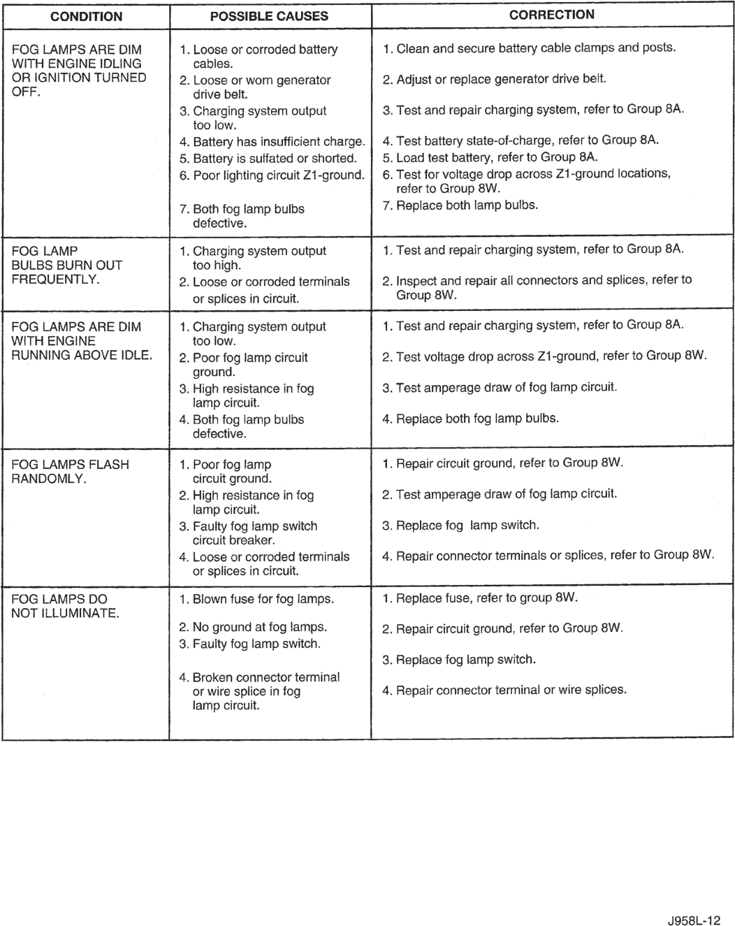
FOG LAMPS ARE DIM 1. Loose or corroded battery 1. Clean and secure battery cable clamps and posts.
WITH ENGINE IDLING cables.
OR IGNITION TURNED 2. Loose or worn generator 2. Adjust or replace generator drive belt.
OFF. drive belt.
3. Charging system output 3. Test and repair charging system, refer to Group 8A.
too low.
4. Battery has insufficient charge. | 4. Test battery state-of-charge, refer to Group 8A.
5. Battery is sulfated or shorted. 5. Load test battery, refer to Group 8A.
6. Poor lighting circuit Z1-ground. | 6. Test for voltage drop across Z1-ground locations,
refer to Group 8W.
7. Both fog lamp bulbs 7. Replace both lamp bulbs.
defective.
FOG LAMP 1. Charging system output 1. Test and repair charging system, refer to Group 8A.
BULBS BURN OUT too high.
FREQUENTLY. 2. Loose or corroded terminals 2. Inspect and repair all connectors and splices, refer to
or splices in circuit. Group 8W.
FOG LAMPS ARE DIM 1. Charging system output 1. Test and repair charging system, refer to Group 8A.
WITH ENGINE too low.
RUNNING ABOVE IDLE. | 2. Poor fog lamp circuit 2. Test voltage drop across Z1-ground, refer to Group 8W.
ground.
3. High resistance in fog 3. Test amperage draw of fog lamp circuit.
lamp circuit.
4. Both fog lamp bulbs 4. Replace both fog lamp bulbs.
defective.
FOG LAMPS FLASH 1. Poor fog lamp 1. Repair circuit ground, refer to Group 8W.
RANDOMLY. circuit ground.
2. High resistance in fog 2. Test amperage draw of fog lamp circuit.
lamp circuit.
3. Faulty fog lamp switch 3. Replace fog lamp switch.
circuit breaker.
4. Loose or corroded terminals 4. Repair connector terminals or splices, refer to Group 8W.
or splices in circuit.
FOG LAMPS DO 1. Blown fuse for fog lamps. 1. Replace fuse, refer to group 8W.
NOT ILLUMINATE.
2. No ground at fog lamps. 2. Repair circuit ground, refer to Group 8W.
3. Faulty fog lamp switch.
3. Replace fog lamp switch.
4. Broken connector terminal
or wire splice in fog 4. Repair connector terminal or wire splices.
lamp circuit.
J958L-12
DAYTIME RUNNING LAMP DIAGNOSIS
DAYTIME RUNNING LAMP DIAGNOSIS
DAYTIME RUNNING LAMPS DO NOT WORK
1. Poor connection at DRL module. 2. Parking brake engaged. 3. Parking brake circuit shorted to ground. 4. Headlamp circuit shorted to ground. 5. Defective DRL module.
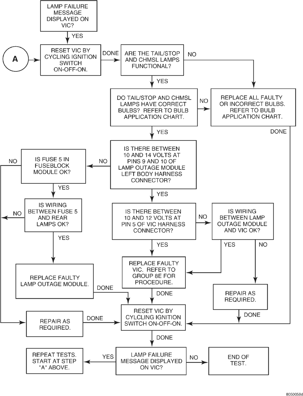
LAMP OUTAGE MODULE DIAGNOSIS
NOTE: The Lamp Outage Module contains an internal circuit breaker. When the module senses an overload it will trip the circuit breaker and illumi-
CONDITION POSSIBLE CAUSES CORRECTION
1. Secure connector on DRL module. 2. Disengage parking brake. 3. Check voltage on pin 3 of module, refer to Group 8W. 4. Check L3 circuit, refer to Group 8W. 5. Replace DRL module.
nate a failure in the Vehicle Information Center (VIC). The circuit breaker will reset once the vehicle is turned off for approximately 60 seconds. Continuous tripping of the circuit breaker may indicate a circuit problem.
LAMP OUTAGE MODULE DIAGNOSIS
HEADLAMP ALIGNMENT
INDEX
GENERAL INFORMATION
HEADLAMP ALIGNMENT . . . . . . . . . . . . . . . . . . . 6 SERVICE PROCEDURES
FOG LAMP ADJUSTMENT . . . . . . . . . . . . . . . . . . 7 HEADLAMP ADJUSTMENT USING ALIGNMENT
GENERAL INFORMATION
HEADLAMP ALIGNMENT
Headlamps can be aligned using the screen method provided in this section. Alignment Tool C-4466-A or equivalent can also be used. Refer to instructions provided with the tool for proper procedures. The preferred headlamp alignment setting is 0 for the left/right adjustment and 1( down for the up/down adjustment.
SERVICE PROCEDURES
HEADLAMP ALIGNMENT PREPARATION
(1) Verify headlamp dimmer switch and high beam indicator operation.
(2) Correct defective components that could hinder proper headlamp alignment.
(3) Verify proper tire inflation. (4) Clean headlamp lenses. (5) Verify that luggage area is not heavily loaded. (6) Fuel tank should be FULL. Add 2.94 kg (6.5 lbs.) of weight over the fuel tank for each estimated gallon of missing fuel.
ALIGNMENT SCREEN PREPARATION
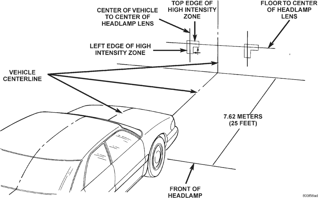
(1) Position vehicle on a level surface perpendicular to a flat wall 7.62 meters (25 ft) away from front of headlamp lens (Fig. 1).
(2) If necessary, tape a line on the floor 7.62 meters (25 ft) away from and parallel to the wall.
(3) Measure from the floor up 1.27 meters (5 ft) and tape a line on the wall at the centerline of the page page
SCREEN . . . . . . . . . . . . . . . . . . . . . . . . . . . . . . 6 HEADLAMP ALIGNMENT PREPARATION . . . . . . . 6 SPECIAL TOOLS
SPECIAL TOOLS—HEADLAMP ALIGNMENT . . . . 8 vehicle. Sight along the centerline of the vehicle (from rear of vehicle forward) to verify accuracy of the line placement.
(4) Rock vehicle side-to-side three times to allow suspension to stabilize.
(5) Jounce front suspension three times by pushing downward on front bumper and releasing.
(6) Measure the distance from the center of headlamp lens to the floor. Transfer measurement to the alignment screen (with tape). Use this line for up/down adjustment reference.
(7) Measure distance from the centerline of the vehicle to the center of each headlamp being aligned. Transfer measurements to screen (with tape) to each side of vehicle centerline. Use these lines for left/ right adjustment reference.
HEADLAMP ADJUSTMENT USING ALIGNMENT SCREEN
A properly aimed low beam will project the top edge of high intensity pattern on the screen from 50 mm (2 in.) above to 50 mm (2 in.) below headlamp centerline. The side-to-side left edge of high intensity pattern should be from 50 mm (2 in.) left to 50 mm (2 in.) right of headlamp centerline (Fig. 1). The preferred headlamp alignment is 0 for the left/ right adjustment and 1( down for the up/down adjustment. The high beams on a vehicle with aero headlamps cannot be aligned. The high beam pattern should be correct when the low beams are aligned properly.
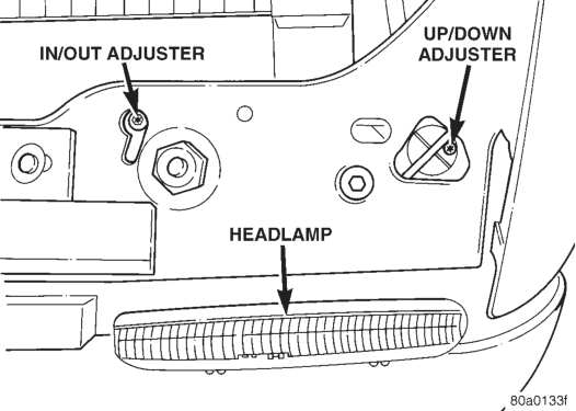
To adjust headlamp aim, rotate alignment screws (Fig. 2).
Fig. 1 Headlamp Alignment Screen—Typical
FOG LAMP ADJUSTMENT
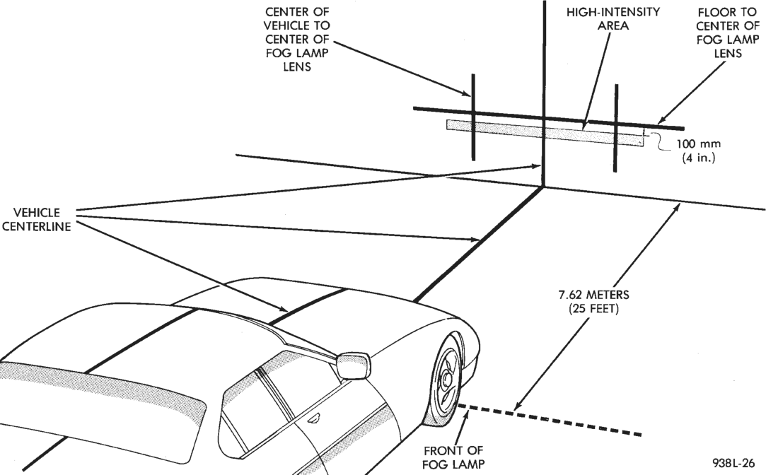
Prepare an alignment screen. A properly aligned fog lamp will project a pattern on the alignment screen 100 mm (4 in.) below the fog lamp centerline and straight ahead (Fig. 3).
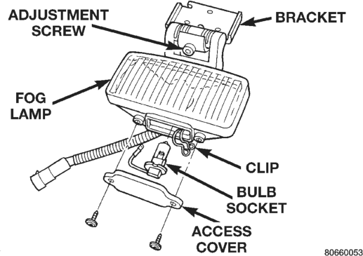
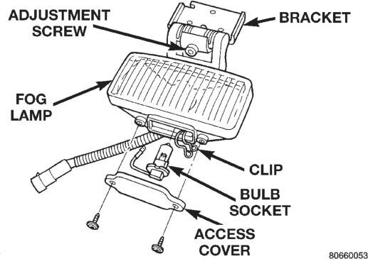
Rotate the adjustment screw (Fig. 4) to obtain the correct pattern.
SPECIAL TOOLS
SPECIAL TOOLS—HEADLAMP ALIGNMENT
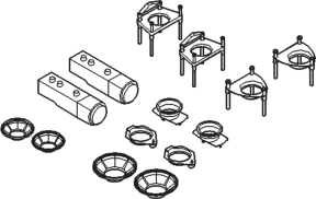
Headlamp Aiming Kit C-4466–A
LAMP BULB SERVICE
INDEX
REMOVAL AND INSTALLATION
CARGO LAMP BULB . . . . . . . . . . . . . . . . . . . . . 12 CENTER HIGH MOUNTED STOP LAMP
(CHMSL) BULB . . . . . . . . . . . . . . . . . . . . . . . . 10 DOME LAMP BULB . . . . . . . . . . . . . . . . . . . . . . 11 DOOR COURTESY LAMP BULB . . . . . . . . . . . . . 11 FOG LAMP BULB . . . . . . . . . . . . . . . . . . . . . . . . . 9 HEADLAMP BULB . . . . . . . . . . . . . . . . . . . . . . . . 9 LICENSE PLATE LAMP BULB . . . . . . . . . . . . . . 10
REMOVAL AND INSTALLATION
HEADLAMP BULB
REMOVAL
(1) Lift hood to access lamps. If clearance is minimal behind the headlamp assembly, refer to the Headlamp Removal/Installation procedure for bulb replacement.
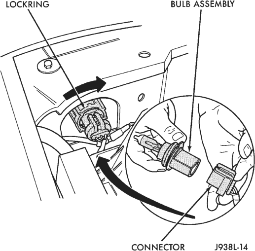
(2) Reach into engine compartment and locate lock ring supporting the headlamp bulb assembly.
(3) Rotate the lock ring 1/8 turn counterclockwise (Fig. 1).
(4) Pull the bulb straight out from the housing.
page page
OVERHEAD CONSOLE READING LAMP BULB . 11 PARKING LAMP BULB . . . . . . . . . . . . . . . . . . . . 10 READING LAMP BULB . . . . . . . . . . . . . . . . . . . . 11 TAIL, STOP, TURN SIGNAL, BACK-UP AND
SIDE MARKER LAMP BULBS . . . . . . . . . . . . . 10 TURN SIGNAL AND SIDE MARKER LAMP BULB . . . . . . . . . . . . . . . . . . . . . . . . . . . . . . . . . . . . . . . 10
UNDERHOOD LAMP BULB . . . . . . . . . . . . . . . . . 11 VISOR VANITY LAMP BULB . . . . . . . . . . . . . . . . 11
INSTALLATION
CAUTION: Do not touch the bulb glass with fingers or other oily surfaces. Reduced bulb life will result.
(1) Install new bulb. (2) Position bulb assembly in the lamp housing and turning the lock ring 1/8 turn clockwise to secure.
FOG LAMP BULB
REMOVE
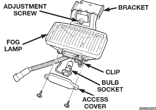
(1) Remove the screws attaching the access cover to the bottom of the fog lamp (Fig. 2).
(2) Remove spring clip securing bulb to fog lamp. (3) Disconnect wire connectors at bulb. (4) Remove bulb element from fog lamp.
INSTALLATION
CAUTION: Do not touch the bulb glass with fingers or other oily surfaces. Reduced bulb life will result.
(1) Position bulb element in fog lamp. (2) Connect wire connectors at bulb. (3) Install spring clip securing bulb to fog lamp. (4) Install screws attaching the access cover to the bottom of the fog lamp (Fig. 2).
PARKING LAMP BULB
REMOVAL
(1) Remove lamp from vehicle (2) Rotate socket counterclockwise and pull socket from lamp.
(3) Pull bulb to from socket.
INSTALLATION
(1) Position bulb in socket and push into place. (2) Position socket in lamp and rotate socket clockwise.
(3) Install the lamp.
TURN SIGNAL AND SIDE MARKER LAMP BULB
REMOVAL
(1) Remove parking lamp. (2) Remove turn signal/side marker lamp. (3) Rotate turn signal bulb socket counterclockwise, press in on bulb and rotate 1/4 turn to remove.
(4) Rotate sidemarker bulb socket counterclockwise grasp and pull from lamp.
INSTALLATION
(1) Install side marker lamp bulb. (2) Install turn signal lamp bulb. (3) Install turn signal/side marker lamp. (4) Install parking lamp.
TAIL, STOP, TURN SIGNAL, BACK-UP AND SIDE MARKER LAMP BULBS
The stop, turn signal, back-up and rear side marker lamp bulbs are incorporated into the tail lamp.
REMOVAL
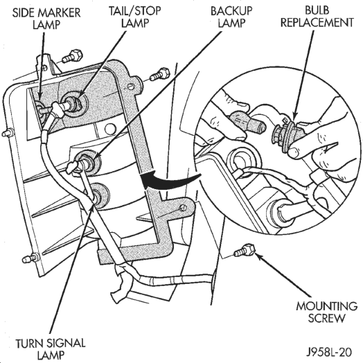
(1) Remove tail lamp. (2) Grasp bulb socket and rotate counterclockwise. Separate socket from lamp.
(3) Rotate bulb in the socket counterclockwise and remove bulb from socket (Fig. 3).
INSTALLATION
(1) Position bulb in socket and rotate clockwise.
(2) Position bulb socket in lamp and rotate clockwise.
(3) Install lamp.
LICENSE PLATE LAMP BULB
REMOVAL
(1) Remove screws attaching license plate lamp to license plate housing.
(2) Separate lamp from housing. (3) Grasp bulb and pull from bulb socket.
INSTALLATION
(1) Position bulb in socket and press into place. (2) Position license plate lamp in license plate housing.
(3) Install screws attaching license plate lamp to license plate housing.
CENTER HIGH MOUNTED STOP LAMP (CHMSL) BULB
REMOVAL
(1) Remove CHMSL from liftgate. (2) Turn bulb socket 1/4 turn counterclockwise. (3) Separate socket from lamp. (4) Grasp bulb and pull from socket.
INSTALLATION
(1) Position bulb in socket and press into place. (2) Position socket in lamp. (3) Turn bulb socket 1/4 turn clockwise. (4) Install CHMSL.
UNDERHOOD LAMP BULB
REMOVAL
(1) Disconnect the wire harness connector from the underhood lamp.
(2) Rotate the bulb counterclock-wise. Remove it from the lamp socket.
INSTALLATION
(1) Insert the replacement bulb in the lamp base socket. Rotate it clockwise.
(2) Connect the wire harness connector to the lamp.
VISOR VANITY LAMP BULB
REMOVAL
(1) Using a small flat blade, carefully pry each corner of lens outward from lamp.
(2) Separate lens from lamp. (3) Grasp bulb and pull outward.
INSTALLATION
(1) Position bulb in socket and push into place. (2) Position lens on lamp and snap into place.
OVERHEAD CONSOLE READING LAMP BULB
REMOVAL
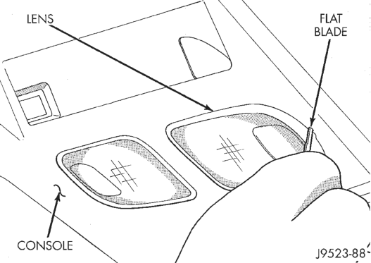
(1) Insert a flat blade screwdriver in slot at front of lens (Fig. 4).
(2) Rotate the screwdriver until lens snaps out of the housing.
(3) Remove lens from housing. (4) Remove bulb from terminals.
INSTALLATION
(1) Insert bulb into reading lamp terminals. (2) Replace lens by holding lens level and pushing rearward into housing.
(3) Push lens up to snap into housing.
DOME LAMP BULB
REMOVAL
(1) Insert a flat blade screwdriver in slot at front of lens.
(2) Rotate the screwdriver until lens snaps out of the housing.
(3) Remove lens from housing. (4) Remove bulb from socket.
INSTALLATION
(1) Insert bulb into reading lamp terminals. (2) Replace lens by holding lens level and pushing rearward into housing.
(3) Push lens up to snap into housing.
READING LAMP BULB
REMOVAL
(1) Insert a flat blade screwdriver in slot at front of lens.
(2) Rotate the screwdriver until lens snaps out of the housing.
(3) Remove lens from housing. (4) Remove bulb from terminals.
INSTALLATION
(1) Insert bulb into reading lamp terminals. (2) Replace lens by holding lens level and pushing rearward into housing.
(3) Push lens up to snap into housing.
DOOR COURTESY LAMP BULB
REMOVAL
(1) Remove door trim panel. Refer to Group 23, Body Components for service procedure.
(2) Remove bulb socket from lamp. (3) Pull bulb from socket.
INSTALLATION
(1) Position bulb in socket and press into place. (2) Install bulb socket in lamp. (3) Install door trim panel.
CARGO LAMP BULB
REMOVAL
(1) Insert a flat blade screwdriver in slots provided at lower portion of lens.
(2) Rotate screwdriver upward until lens snaps out of housing.
(3) Remove lens from housing.
(4) Remove bulb from bulb socket.
INSTALLATION
(1) Position bulb in socket and press into place. (2) Insert upper tabs of lens into lens housing. (3) Snap lower portion of lens into slots at lens housing.
LAMP SERVICE
INDEX
REMOVAL AND INSTALLATION
CARGO LAMP . . . . . . . . . . . . . . . . . . . . . . . . . . 16 CENTER HIGH MOUNTED STOP LAMP
(CHMSL) . . . . . . . . . . . . . . . . . . . . . . . . . . . . . 15 DOME/READING LAMP . . . . . . . . . . . . . . . . . . . 15 DOOR COURTESY LAMP . . . . . . . . . . . . . . . . . 16 FOG LAMP . . . . . . . . . . . . . . . . . . . . . . . . . . . . . 13 HEADLAMP . . . . . . . . . . . . . . . . . . . . . . . . . . . . 13
REMOVAL AND INSTALLATION
HEADLAMP
REMOVAL
(1) Grasp lower edge of headlamp lens and pull straight back (away) from grille opening reinforcement (GOR). Disengage lower adjuster pivots from lens assembly.
(2) Grasp upper edge of headlamp lens. Pull straight back (away) from grille opening reinforcement (GOR). Disengage upper adjuster pivot from lens assembly.
(3) Rotate bulb lock ring counterclockwise. and remove ring and bulb from lens.
INSTALLATION
(1) Replace by seating the assembly in the lamp housing and turning the lock ring 1/8 turn clockwise to secure.
(2) Align upper adjust pivot into headlamp opening and snap into place.
(3) Snap lower adjuster pivots into place.
FOG LAMP
REMOVAL
(1) Remove adjustment screw (Fig. 1). (2) Disengage fog lamp electrical connector. (3) Separate fog lamp from vehicle.
INSTALLATION
(1) Position fog lamp at vehicle. (2) Engage fog lamp electrical connector. (3) Install adjustment screw (Fig. 1).
page page
LICENSE PLATE LAMP . . . . . . . . . . . . . . . . . . . 14 PARKING LAMP . . . . . . . . . . . . . . . . . . . . . . . . . 13 TAIL, STOP, TURN SIGNAL, BACK-UP AND
SIDE MARKER LAMP . . . . . . . . . . . . . . . . . . . 14 TURN SIGNAL AND SIDE MARKER LAMP . . . . . 14 UNDERHOOD LAMP . . . . . . . . . . . . . . . . . . . . . 15 VISOR VANITY LAMP . . . . . . . . . . . . . . . . . . . . . 15
(4) Align fog lamp.
PARKING LAMP
REMOVAL
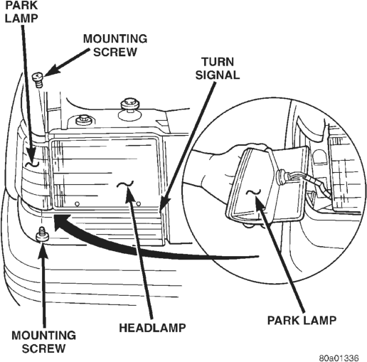
The parking lamp is mounted on the side of the GOR next to headlamp assembly.
(1) Open hood. (2) Remove screws which hold the parking lamp in position (Fig. 2).
(3) Rotate lamp socket counterclockwise and pull socket from lamp.
INSTALLATION
(1) Position lamp socket in lamp and rotate clockwise.
(2) Position lamp in place and install the screws.
TURN SIGNAL AND SIDE MARKER LAMP
REMOVAL
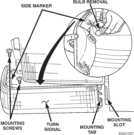
(1) Remove parking lamp. (2) Remove the screws and slide lamp outboard to expose the socket (Fig. 3).
(3) Remove turn signal socket from lamp. (4) Remove sidemarker socket from lamp. (5) Separate lamp from vehicle.
INSTALLATION
(1) Install turn signal lamp socket. (2) Install side marker lamp socket. (3) Slide lamp into slot provided on inboard side of headlamp assembly.
(4) Install screws. (5) Install parking lamp.
TAIL, STOP, TURN SIGNAL, BACK-UP AND SIDE MARKER LAMP
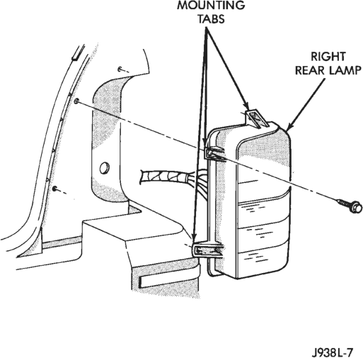
The stop, turn signal, back-up and rear side marker lamps are incorporated into the tail lamp.
REMOVAL
(1) Remove screws attaching lamp to body (Fig. 4). (2) Remove bulb sockets from lamp. (3) Separate lamp from vehicle.
INSTALLATION
(1) Position lamp at vehicle and install bulb sockets.
(2) Position lamp on vehicle and install screws.
LICENSE PLATE LAMP
REMOVAL
(1) Remove screws attaching license plate lamp to license plate housing.
(2) Separate lamp from housing. (3) Grip bulb socket, rotate counterclockwise and separate bulb socket from license plate lamp.
INSTALLATION
(1) Position bulb socket in license plate lamp and turn clockwise.
(2) Position license plate lamp in license plate housing.
(3) Install screws attaching license plate lamp to license plate housing.
CENTER HIGH MOUNTED STOP LAMP (CHMSL)
REMOVAL
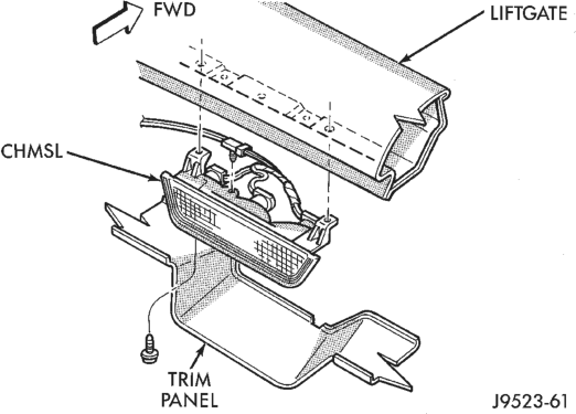
(1) Raise liftgate. (2) Remove upper liftgate trim panel. (3) Remove CHMSL lamp mounting screws (Fig. 5). (4) Remove CHMSL lamp. (5) Turn bulb socket 1/4 turn counterclockwise. (6) Separate socket from lamp.
INSTALLATION
(1) Position socket in lamp. (2) Turn bulb socket 1/4 turn clockwise. (3) Position CHMSL lamp in place and install mounting screws.
(4) Install upper liftgate trim panel.
UNDERHOOD LAMP
REMOVAL
When equipped, the underhood lamp is installed on the hood right, rear panel. The lamp is on when hood is opened by way of liquid ON/OFF switch that is integral with lamp base.
(1) Open hood. (2) Remove screw attaching lamp support bracket to hood (Fig. 6).
(3) Disengage connector for underhood lamp. (4) Separate lamp from vehicle.
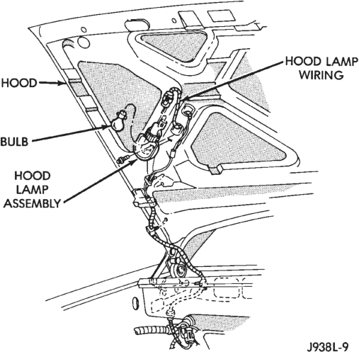
INSTALLATION
(1) Engage connector for underhood lamp. (2) Position lamp on hood and install screw.
VISOR VANITY LAMP
REMOVAL
(1) Fold down sunvisor. (2) Starting at the base of the lamp assembly and working right-to-left, use a small flat blade, carefully pry lamp from visor.
(3) Disconnect visor lamp wire connector and remove from vehicle.
INSTALLATION
(1) Position visor lamp at visor and connect visor lamp wire connector.
(2) Position visor lamp in visor and press into place.
DOME/READING LAMP
REMOVAL
(1) Insert a flat blade screwdriver in slot at the center of the lamp housing. Rotate screwdriver upward and unsnap dome lamp lens.
(2) Pull lens downward. Remove it from lamp housing.
(3) Remove the lamp housing retaining screws (Fig. 7).
(4) Push housing forward and release housing from bracket.
(5) Disconnect wire harness connectors. (6) Remove lamp housing from headliner cavity.
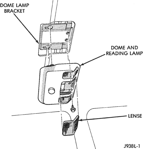
INSTALLATION
(1) Position dome/reading lamp housing at headliner cavity.
(2) Connect wire harness connectors. (3) Locate rear pods of the lamp in the slots of the dome lamp bracket. Push lamp housing up and to rear.
(4) Install the lamp housing screws. (5) Position dome lamp lens at lamp housing. Snap lens into housing.
DOOR COURTESY LAMP
REMOVAL
(1) Remove door trim panel. Refer to Group 23, Body Components for service procedure.
(2) Remove bulb socket from lamp. (3) Depress lamp locking tabs and separate lamp from trim panel.
INSTALLATION
(1) Position lamp in trim panel and snap into place. (2) Install bulb socket in lamp. (3) Install door trim panel.
CARGO LAMP
REMOVAL
(1) Insert a flat blade screwdriver in slots provided at lower portion of lens.
(2) Rotate screwdriver upward until lens snaps out of housing.
(3) Remove lens from housing (Fig. 8). (4) Remove screws attaching liftgate opening upper trim panel/cargo lamp to liftgate opening roof panel.
(5) Separate trim panel from roof panel. (6) Disengage electrical connector for cargo lamp.
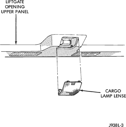
INSTALLATION
(1) Position trim panel/cargo lamp at liftgate opening.
(2) Engage electrical connector for cargo lamp. (3) Install screws attaching liftgate opening upper trim panel/cargo lamp to liftgate opening roof panel.
(4) Position lens on cargo lamp and snap into place.
LAMP SYSTEMS
INDEX
GENERAL INFORMATION
AUTO HEADLAMP SENSOR . . . . . . . . . . . . . . . 17 DAYTIME RUNNING LAMP SYSTEM . . . . . . . . . 17 LAMP OUTAGE MODULE . . . . . . . . . . . . . . . . . . 17
GENERAL INFORMATION
DAYTIME RUNNING LAMP SYSTEM
ZJ vehicles built for use in Canada are equipped with a Daytime Running Lamp System (DRL). The DRL system operates the headlamp at 50% illumination with the headlamp switch OFF, park brake released and the ignition in the RUN position. The DRL system is controlled by the Daytime Running Lamp Module located in the engine compartment attached to the Power Distribution Center (PDC) bracket. The DRL module overides the headlamp switch when the headlamps are turned OFF. The headlamps operate normally when the headlamps are turned ON.
LAMP OUTAGE MODULE
The Lamp Outage Module will indicate a tail lamp, stop lamp, or a CHMSL bulb failure. A display will illuminate in the Vehicle Information Center (VIC), displaying the failure.
Details for the VIC can be found in Group 8E, Vehicle Information Center. For circuit information, refer to Group 8W, Wiring Diagrams.
The Lamp Outage Module is located behind the left quarter trim panel.
Connecting trailer lights to the body harness at the rear of the vehicle can cause damage to the lamp outage module. The lamp outage module is designed to handle a 5 amp current load. This is adequate for the operation of the vehicles lighting system. When additional lights are added to the system such as trailer lights, the 5 amp limit can be exceeded. This can cause failure of the lamp outage module.
If trailer towing is required and the vehicle is not equipped with a trailer tow package, the MOPAR accessory trailer towing harnesses are the only approved method to provide additional trailer lights. These harnesses are designed to provide current to the trailer lights but bypass the lamp outage module.
AUTO HEADLAMP SENSOR
The auto headlamp sensor is the key sensor for the auto headlamp system. The sensor needs real sunpage page
REMOVAL AND INSTALLATION
AUTO HEADLAMP SENSOR . . . . . . . . . . . . . . . 17 DAYTIME RUNNING LIGHT MODULE . . . . . . . . . 17 LAMP OUTAGE MODULE . . . . . . . . . . . . . . . . . . 18 light to properly register the light level. When auto headlamps are enabled indoors, the headlamps may be turned on. The sensor is located in the center of the defroster grille at the base of the windshield.
REMOVAL AND INSTALLATION
DAYTIME RUNNING LIGHT MODULE
REMOVAL
(1) Open hood. (2) Disconnect electrical connector from module. (3) Remove screws holding module to PDC bracket (Fig. 1).
(4) Separate module from bracket.
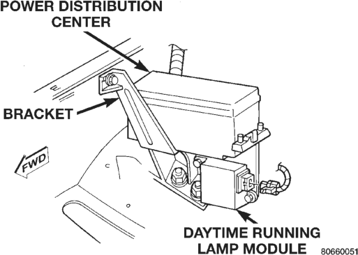
INSTALLATION
(1) Reverse the removal procedures.
AUTO HEADLAMP SENSOR
REMOVAL
(1) Using a trim stick, gently pry defroster bezel out of dash pad.
(2) Unplug auto headlamp sensor connector. (3) Snap out sensor from bezel.
INSTALLATION
(1) Reverse the removal procedure.
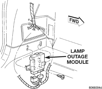
LAMP OUTAGE MODULE
REMOVAL
(1) Disconnect battery negative cable. (2) Remove spare tire from carrier. (3) Remove access door. (4) Remove screw holding module to inner quarter panel (Fig. 2).
(5) Disconnect wiring connectors at module. (6) Separate lamp outage module from vehicle.
INSTALLATION
(1) Connect wiring connectors at module. (2) Install screw holding module to inner quarter panel.
(3) Install access door. (4) Install spare tire.
(5) Connect battery negative cable.
BULB APPLICATION
INDEX
GENERAL INFORMATION
GENERAL INFORMATION . . . . . . . . . . . . . . . . . 19 SPECIFICATIONS
EXTERIOR LAMPS . . . . . . . . . . . . . . . . . . . . . . . 19
GENERAL INFORMATION
GENERAL INFORMATION
The following Bulb Application Tables lists the lamp title on the left side of the column and trade number or part number on the right.
CAUTION: Do not use bulbs that have a higher candle power than the bulb listed in the Bulb Application Table. Damage to lamp can result. Do not touch halogen bulbs with fingers or other oily surfaces. Bulb life will be reduced.
SPECIFICATIONS
EXTERIOR LAMPS
LAMP BULB Back-up. . . . . . . . . . . . . . . . . . . . . . . . . . . . . . . .1156 Center High Mounted Stoplamp. . . . . . . . . . . . . .921 Fog lamp . . . . . . . . . . . . . . . . . . . . . . . . . . . . . . . .H3 Front Turn Signal . . . . . . . . . . . . . . . . . . . . .1295NA Front Side Marker. . . . . . . . . . . . . . . . . . . . . .194NA Headlamp . . . . . . . . . . . . . . . . . . . . . . . . . . . . . .9004 License Plate . . . . . . . . . . . . . . . . . . . . . . . . . . . .168 Tail/Stop . . . . . . . . . . . . . . . . . . . . . . . . . . . . . . .2057 Rear Turn Signal . . . . . . . . . . . . . . . . . . . . . . . .1156 Underhood Lamp . . . . . . . . . . . . . . . . . . . . . . . . .105
INTERIOR LAMPS
Service procedures for most of the lamps in the instrument panel, are located in Group 8E. Some page page
INTERIOR LAMPS . . . . . . . . . . . . . . . . . . . . . . . 19 components have lamps that can only be serviced by an Authorized Service Center (ASC) after the component is removed from the vehicle. Contact local dealer for location of nearest ASC.
LAMP BULB A/C Heater . . . . . . . . . . . . . . . . . . . . . . . . . .4720843 Ash Receiver. . . . . . . . . . . . . . . . . . . . . . . . . . . . . .37 Cigarette Lighter . . . . . . . . . . . . . . . . . . . . . . . . . .53 Climate Control . . . . . . . . . . . . . . . . . . . . . . . . . . .74 Console Floor Shifter . . . . . . . . . . . . . . . . . . . . . .194 Dome/Reading . . . . . . . . . . . . . . . . . . . . . . . . . . .561 Door Courtesy. . . . . . . . . . . . . . . . . . . . . . . . . . . .168 Front Reading . . . . . . . . . . . . . . . . . . . . . . . . . . .906 Glove Compartment . . . . . . . . . . . . . . . . . . . . . . .194 Hazard Lamp . . . . . . . . . . . . . . . . . . . . . . . . . . . . .74 Heater . . . . . . . . . . . . . . . . . . . . . . . . . . . . . . . . .194 Overhead Console. . . . . . . . . . . . . . . . . . . . . . . . .212 Radio. . . . . . . . . . . . . . . . . . . . . . . . . . . . . . . . . .ASC Rear Cargo . . . . . . . . . . . . . . . . . . . . . . . . . . . . . .212 Rocker Switch. . . . . . . . . . . . . . . . . . . . . . . . . . . . .37 Shift Lamp . . . . . . . . . . . . . . . . . . . . . . . . . . . . . . .74 Transfer Case Shifter . . . . . . . . . . . . . . . . . . . . . .194 Theft Alarm . . . . . . . . . . . . . . . . . . . . . . . . . . . . . .74 Under Panel Courtesy . . . . . . . . . . . . . . . . . . . . . .89