Instrument Panel Systems — 1996 Jeep Grand Cherokee ZJ Service Manual
Pages 327–357 · 31 pages · 17 words repaired
GENERAL INFORMATION
INTRODUCTION
This group is responsible for covering the vehicle instrument panel. However, because the instrument panel serves as the vehicle’s command center, it is a very complex unit. The instrument panel is designed to house the controls and monitors for standard and optional powertrains, climate control systems, audio systems, lighting systems, safety systems and many other comfort or convenience items. It is also designed so that all of the controls and monitors can be safely reached and/or viewed by the vehicle operator, while still allowing relative ease of access to these items for service.
Complete service information coverage for all of the systems and components housed in the instrument panel in this section of the service manual would not be practical. It would result in a great deal of duplication and make this group too large for the information to be easily accessed and used. Therefore, the information found in this group has been limited as follows:
• General Information - Covers non-electrical components and features of the instrument panel that are not related to other systems.
• Description and Operation - Covers gauges and their sending units, warning lamps and their switches, and instrument panel illumination lamps.
• Diagnosis and Testing - Covers gauges and their sending units, warning lamps and their switches, and instrument panel illumination lamps.
• Removal and Installation - Covers components installed on or in the instrument panel that require removal for diagnosis or service of instrument panel components covered in this group.
For more information on components or systems not covered above, refer to the proper group in this manual. If you are uncertain as to the proper group, refer to the Component and System Index at the back of this manual. Refer to Group 8W - Wiring Diagrams for complete circuit descriptions and diagrams.
INSTRUMENT PANEL
Modular instrument panel construction allows all of the gauges and controls to be serviced from the front of the panel. In addition, most of the instrument panel wiring or heating and air conditioning components can be accessed without complete instrument panel removal. If necessary, the instrument panel can be removed from the vehicle as an assembly.
Removal of the switch pod bezels allows access to most switches and the climate controls. Removal of the instrument cluster bezel allows access to the cluster assembly and the radio. Removal of the cluster assembly allows access to the individual gauges, illumination and indicator lamp bulbs, and most of the instrument panel wiring.
Removal of the steering column cover/knee blocker provides access to the steering column mounts, the body control module, the gearshift interlock mechanism, and additional instrument panel and steering column wiring. Removal of the right lower instrument panel module and center bezel unit allows access to the Vehicle Information Center (VIC), Graphic Display Module (GDM), additional instrument panel wiring, the in-vehicle temperature sensor, and other heating and air conditioning components.
Removal of the instrument panel cowl top panel allows access to the instrument panel speakers, the solar sensor, and the automatic headlamp light sensor/vehicle theft security system lamp. Removal of the instrument panel top cover allows access to the passenger’s side airbag module.
INSTRUMENT CLUSTERS
One basic instrument cluster option is offered on Grand Cherokee models. This cluster is an electromechanical unit that utilizes integrated circuitry and information carried on the Chrysler Collision Detection (CCD) data bus network for control of all gauges and most indicator lamps. This cluster also incorporates a vacuum fluorescent display tube for the digital odometer/trip odometer display functions. Some variations of the cluster exist due to optional equipment and regulatory requirements.
The cluster includes the following analog gauges: • Coolant temperature gauge • Fuel gauge • Oil pressure gauge • Speedometer • Tachometer • Voltmeter. This cluster includes provisions for the following indicator lamps:
• Airbag indicator lamp • Anti-lock brake system lamp • Brake warning lamp • Check gauges lamp • Cruise-on indicator lamp • Headlamp high beam indicator lamp • Low fuel warning lamp • Malfunction indicator (Check Engine) lamp • Master lighting indicator lamp (export) • Seat belt reminder lamp • Turn signal indicator lamps • Upshift indicator lamp (export) • Wait-to-start lamp (export-diesel) • Water-in-fuel lamp (export-diesel).
GRAPHIC DISPLAY MODULE
A Graphic Display Module (GDM) is standard equipment on all Grand Cherokee models, unless the vehicle is equipped with the optional Vehicle Information Center (VIC). The GDM is mounted in the lower center stack area of the instrument panel, above the ash receiver and below the climate controls.
The display consists of a back-lit screen with a vehicle outline. The two rear wheels of the vehicle are illuminated by a lamp when the transfer case is engaged in any two-wheel drive operating mode. The two front wheels are also illuminated when the transfer case is engaged in any four-wheel drive operating mode.
The GDM also has up to three lamps, which indicate whether the four-wheel drive mode selected is Lo, Part-Time, or Full-Time. The number of operational indicator lamps may vary, depending upon the optional four-wheel drive transfer case in the vehicle. A switch on the transfer case is hard-wired to the GDM and energizes the proper wheels and indicator lamps.
The GDM bulbs can be serviced. However, if any other part of the GDM is damaged or faulty, the entire GDM must be replaced.
VEHICLE INFORMATION CENTER
The Vehicle Information Center (VIC) is an available option on Grand Cherokee models. The VIC module replaces the standard equipment Graphic Display Module. The VIC is mounted in the lower center stack area of the instrument panel, above the ash receiver and below the climate controls.
The VIC consists of a multi-colored vacuum fluorescent display screen with a vehicle outline. The VIC is able to display four functions in a choice of five languages. The display functions include:
• Current time (12 or 24 hour clock), day, and date • Monitor specific vehicle operating systems and alert the driver of a malfunction in a monitored system
• Provide service reminders or the distance to the next service interval
• The current transfer case mode of operation. The display language choices include: • English • French • German • Italian • Spanish. The VIC receives input from hard-wired sensors and over the Chrysler Collision Detection (CCD) data bus network. In response to these inputs the VIC offers a combination of graphic and message displays, and provides requests for audible chime alerts to the body control module on the CCD data bus.
Refer to the owner’s manual for more information on the VIC controls, operation, and setting procedures. For diagnosis of the VIC module or the CCD data bus, refer to the proper Body Diagnostic Procedures Manual. The VIC module cannot be repaired. If damaged or faulty, the entire module must be replaced.
GAUGES
With the ignition switch in the On or Start positions, voltage is supplied to all gauges through the instrument cluster electronic circuit board. With the ignition switch in the Off position, voltage is not supplied to the gauges. The gauges do not accurately indicate any vehicle condition unless the ignition switch is in the On or Start positions.
All gauges, except the odometer, are air core magnetic units. Two fixed electromagnetic coils are located within the gauge. These coils are wrapped at right angles to each other around a movable permanent magnet. The movable magnet is suspended within the coils on one end of a shaft. The gauge needle is attached to the other end of the shaft.
One of the coils has a fixed current flowing through it to maintain a constant magnetic field strength. Current flow through the second coil changes, which causes changes in its magnetic field strength. The current flowing through the second coil is changed by the electronic circuitry in the instrument cluster circuit board, in response to messages received on the Chrysler Collision Detection (CCD) data bus network.
The gauge needle moves as the movable permanent magnet aligns itself to the changing magnetic fields created around it by the electromagnets. These gauges also feature a small fixed permanent magnet which will cause the gauge needles to return to zero after the ignition switch is turned to the Off position.
INDICATOR LAMPS
Indicator lamps are located in the instrument cluster and the Graphic Display Module (GDM) or the Vehicle Information Center (VIC). Those lamps within the instrument cluster are served by the cluster circuit board and connector. Those lamps located in the GDM/VIC are served by the GDM/VIC circuit board and connector.
Most of the indicator lamps are controlled by messages received by the instrument cluster circuitry over the Chrysler Collision Detection (CCD) data bus network. Only the anti-lock brake system lamp, fourwheel drive indicator lamps, lamp outage warning lamp, low coolant level warning lamp, low washer fluid warning lamp, and turn signal indicator lamps are hard-wired. The remaining indicator lamps are activated by the Body Control Module (BCM), Powertrain Control Module (PCM), or Airbag Control Module (ACM) with CCD data bus messages.
BODY CONTROL MODULE
A Body Control Module (BCM) is used on this model to control and integrate many of the vehicle’s electrical functions and features. The BCM contains a central processing unit and interfaces with other modules in the vehicle on the Chrysler Collision Detection (CCD) data bus network.
The CCD data bus network allows the sharing of sensor information. This helps to reduce wiring harness complexity, reduce internal controller hardware, and reduce component sensor current loads. At the same time, this system provides increased reliability, enhanced diagnostics, and allows the addition of many new feature capabilities.
Some of the functions and features that the BCM supports and/or controls, include:
• Chimes • Automatic headlamp control • Headlamp delay • Headlamps on with ignition off and driver’s door open warning
• Key in ignition with ignition off and driver’s door open warning
• Automatic funeral mode • Panel lamp dimming • Vehicle theft security system • Remote keyless entry panic mode • Illuminated entry • Heated rear window and heated outside mirror control
• Intermittent wipe control • Monitoring and transmitting door, hood, liftgate, liftglass ajar data
• Monitoring and transmitting outside ambient temperature data
• Monitoring and transmitting air conditioning select switch data
• Courtesy lamp time-out • Gulf coast country overspeed warning • Door lock inhibit • Electronic odometer/trip odometer • Brake warning lamp • Check gauges lamp • High beam indicator lamp • Seatbelt reminder lamp and chime • Speed sensitive intermittent wipe • Fog lamp control • Remote radio control • Electro-mechanical instrument cluster • BCM diagnostic support • VIC support
• Rolling door locks • Horn chirp upon door lock with remote keyless entry (programmable)
• Low fuel warning chime (programmable) • Headlights on with wipers (programmable - with automatic headlamps only)
The BCM is mounted under the left end of the instrument panel, behind the instrument panel support armature and below the left switch pod. For diagnosis of the BCM or the CCD data bus, refer to the proper Body Diagnostic Procedures Manual. The BCM can only be serviced by an authorized repair station. Refer to the Warranty Policies and Procedures Manual for a listing of authorized repair stations.
JUNCTION BLOCK
The junction block is mounted on the right cowl side kick panel below the right end of the instrument panel. It is concealed behind the right cowl side trim. The junction block serves to simplify and centralize numerous electrical components.
The junction block has cavities for up to 22 bladetype fuses, 3 circuit breakers, 6 ISO micro-relays, and an electronic combination flasher unit. It also eliminates the need for numerous splice connections and serves in the place of a bulkhead connector between the engine compartment, instrument panel, and body wiring harnesses.
The right cowl side trim panel has a snap-fit access cover that can be removed for service of the junction block fuses, but the cowl side trim panel must be removed for service of other junction block components. The junction block cannot be repaired and, if faulty, it must be replaced.
DESCRIPTION AND OPERATION
COOLANT TEMPERATURE GAUGE
The coolant temperature gauge gives an indication of the engine coolant temperature. The instrument cluster circuitry controls the gauge pointer position. The instrument cluster circuitry calculates the proper gauge pointer position based upon an engine coolant temperature message received from the Powertrain Control Module (PCM) on the Chrysler Collision Detection (CCD) data bus.
The PCM uses an input from the engine coolant temperature sensor and internal programming to decide what engine coolant temperature message is required. The PCM then sends the proper message to the instrument cluster and the Body Control Module (BCM) on the CCD data bus.
The BCM monitors the PCM coolant temperature messages. If the PCM message indicates that coolant temperature is high or critical, the BCM sends a message to the instrument cluster to turn on the Check Gauges lamp and to drive the coolant temperature gauge needle to the corresponding high or critical position of the gauge scale.
The engine coolant temperature sensor is installed in a threaded hole that penetrates a coolant passage of the engine. It is a thermistor-type sensor that changes its internal resistance with changes in engine coolant temperature. Refer to Group 14 - Fuel System for more information.
FUEL GAUGE
The fuel gauge gives an indication of the level of fuel in the fuel tank. The instrument cluster circuitry controls the gauge pointer position. The instrument cluster circuitry calculates the proper gauge pointer position based upon a fuel level message received from the Powertrain Control Module (PCM) on the Chrysler Collision Detection (CCD) data bus.
The PCM uses an input from the fuel gauge sending unit and internal programming to decide what fuel level message is required. The PCM then sends the proper message to the instrument cluster on the CCD data bus. If the PCM detects a short or open in the fuel level sending unit circuit, it sends a message on the CCD data bus that will cause the instrument cluster circuitry to position the fuel gauge needle at the Empty stop.
The fuel gauge sending unit is mounted to the electric fuel pump module inside the fuel tank. The sending unit has a float attached to the end of a swingarm. The float moves up or down within the fuel tank as the fuel level changes. As the float moves, an electrical contact on the pivot end of the swing-arm wipes across a resistor coil, which changes the resistance of the sending unit. Refer to Group 14 - Fuel System for more information.
ODOMETER/TRIP ODOMETER
The odometer and the trip odometer share the same vacuum fluorescent digital display tube in the instrument cluster circuit board. Each gives an indication of the distance the vehicle has travelled. However, by depressing the reset knob on the face of the instrument cluster, the display can be switched from odometer to trip odometer, or the trip odometer can be reset to zero. The odometer and trip odometer display the distance values that are received from the Body Control Module (BCM) on the Chrysler Collision Detection (CCD) data bus.
The BCM uses an input from the Powertrain Control Module (PCM) and internal programming to calculate the distance value. The PCM uses an input from the Vehicle Speed Sensor (VSS) to send a distance pulse signal to the BCM on the CCD data bus. The BCM stores both the odometer and trip odometer distance information and sends the proper value to the instrument cluster based upon ignition key-on and trip odometer reset knob messages received on the CCD data bus.
If the instrument cluster is not receiving distance information on the CCD data bus when the ignition switch is turned to the On position, the odometer display will be blank for about four seconds. If there is still no distance message on the CCD data bus after four seconds, the instrument panel circuitry will insert the last normally displayed mileage in the odometer display.
The VSS is a hall-effect sensor that is installed in the transmission or transfer case, and is driven by the output shaft through a speedometer gear. Incorrect tire size, incorrect axle ratio, a faulty or incorrect speedometer gear, or a faulty VSS can each result in inaccurate odometer readings. Refer to Group 14 - Fuel System for more information.
OIL PRESSURE GAUGE
The oil pressure gauge gives an indication of the engine oil pressure. The instrument cluster circuitry controls the gauge pointer position. The instrument cluster circuitry calculates the proper gauge pointer position based upon an engine oil pressure message received from the Powertrain Control Module (PCM) on the Chrysler Collision Detection (CCD) data bus.
The PCM uses an input from the engine oil pressure sensor and internal programming to decide what engine oil pressure message is required. The PCM then sends the proper message to the instrument cluster and the Body Control Module (BCM) on the CCD data bus.
The BCM monitors the PCM engine oil pressure messages. If the PCM message indicates that engine oil pressure is too low, the BCM sends a message to the instrument cluster to turn on the Check Gauges lamp and to drive the oil pressure gauge needle to the zero end of the gauge scale.
The engine oil pressure sensor is installed in a threaded hole that penetrates an oil passage of the engine. The engine oil pressure sensor contains a flexible diaphragm and a variable resistor coil. The diaphragm moves in response to changes in the engine oil pressure. As the diaphragm moves, resistance in the resistor coil increases or decreases.
SPEEDOMETER
The speedometer gives an indication of the current vehicle speed. The instrument cluster circuitry controls the gauge pointer position. The instrument cluster circuitry calculates the proper gauge pointer position based upon a vehicle speed message received from the Powertrain Control Module (PCM) on the Chrysler Collision Detection (CCD) data bus.
The PCM uses an input from the Vehicle Speed Sensor (VSS) and internal programming to calculate what vehicle speed message is required. The PCM then sends the proper message to the instrument cluster on the CCD bus.
The VSS is a hall-effect sensor that is installed in the transmission or transfer case, and is driven by the output shaft through a speedometer gear. Incorrect tire size, incorrect axle ratio, a faulty or incorrect speedometer gear, or a faulty VSS can each result in inaccurate speedometer readings. Refer to Group 14 - Fuel System for more information.
TACHOMETER
The tachometer gives an indication of the engine speed in revolutions-per-minute (rpm). The instrument cluster circuitry controls the gauge pointer position. The instrument cluster circuitry calculates the proper gauge pointer position based upon an engine speed message received from the Powertrain Control Module (PCM) on the Chrysler Collision Detection (CCD) data bus.
The PCM uses an input from the crankshaft position sensor and internal programming to calculate what engine speed message is required. The PCM then sends the proper message to the instrument cluster on the CCD data bus.
The is installed near the rear of the engine, where it is aimed at the trigger wheel attached to the rear flange of the crankshaft. Refer to Group 8D - Ignition Systems for more information.
VOLTMETER
The voltmeter gives an indication of the electrical system voltage. The instrument cluster circuitry controls the gauge pointer position. The instrument cluster circuitry calculates the proper gauge pointer position based upon a system voltage message received from the Powertrain Control Module (PCM) on the Chrysler Collision Detection (CCD) data bus.
The PCM uses an input from the electrical system and internal programming to decide what system voltage message is required. The PCM then sends the proper message to the instrument cluster on the CCD data bus. Refer to Group 8C - Charging System for more information.
AIRBAG INDICATOR LAMP
The airbag indicator lamp gives an indication when the airbag system is faulty or inoperative. The lamp is turned on by the instrument cluster circuitry for about seven seconds when the ignition switch is turned to the On position as a bulb test. After the bulb test, the lamp is controlled by the instrument cluster circuitry based upon a message received from the Airbag Control Module (ACM) on the Chrysler Collision Detection (CCD) data bus.
The ACM continually monitors the airbag system circuits and sensors to decide whether the system is in good operating condition. The ACM then sends the proper message to the instrument cluster on the CCD data bus to turn the lamp on or off. If the ACM turns the lamp on after the bulb test, it indicates the ACM has detected a system malfunction and/or that the airbag system has become inoperative. Each time the instrument cluster circuitry receives a lamp-on message from the ACM, it will light the lamp for twelve seconds or the duration of the airbag system malfunction, whichever is longer.
The airbag indicator lamp also has a lamp backup feature. Following the seat belt reminder lamp display function, if the instrument cluster circuitry has detected an inoperative airbag warning lamp circuit it will flash the seat belt reminder lamp on and off for twenty seconds. Once the instrument cluster circuitry has detected an inoperative airbag warning lamp circuit, if it receives a lamp-on message from the ACM, it will flash the seatbelt reminder lamp for twelve seconds or the duration of the airbag system malfunction, whichever is longer.
Refer to Group 8M - Passive Restraint Systems for more information.
ANTI-LOCK BRAKE SYSTEM LAMP
The Anti-Lock Brake System (ABS) lamp gives an indication when the ABS system is faulty or inoperative. The lamp is hard-wired in the instrument cluster, and is completely controlled by the Controller Anti-lock Brake (CAB). It receives battery voltage through the instrument cluster fused ignition switch output feed circuit, and is grounded by the CAB. The lamp is turned on by the CAB for about two seconds when the ignition switch is turned to the On position as a bulb test. After the bulb test, the CAB turns the lamp on or off based upon the results of the ABS system self-tests.
The CAB continually monitors the ABS circuits and sensors to decide whether the system is in good operating condition. If the CAB turns the lamp on after the bulb test, it indicates that the CAB has detected a system malfunction and/or that the ABS system has become inoperative. Refer to Group 5 - Brakes for more information.
BRAKE WARNING LAMP
The brake warning lamp gives an indication when the parking brake is applied, or when the pressures in the two halves of the split brake hydraulic system are unequal. The lamp is turned on by the instrument cluster circuitry for about four seconds when the ignition switch is turned to the On position as a bulb test. After the bulb test, the lamp is controlled by the instrument cluster circuitry based upon a message received from the Body Control Module (BCM) on the Chrysler Collision Detection (CCD) data bus.
The BCM uses an input from the parking brake switch and/or the brake warning switch to decide whether the brake warning lamp should be on or off. The BCM then sends the proper message to the instrument cluster on the CCD data bus to turn the lamp on or off.
The brake warning switch closes to ground when it senses unequal hydraulic pressures in the two halves of the split brake hydraulic system, possibly due to low brake fluid level or brake fluid leakage. The parking brake switch closes to ground when the parking brake is applied. Refer to Group 5 - Brakes for more information.
CHECK GAUGES LAMP
The check gauges lamp gives an indication when certain gauges reflect a condition requiring immediate attention. The lamp is turned on by the instrument cluster circuitry for about three seconds after the ignition switch is turned to the On position as a bulb test. After the bulb test, the lamp is controlled by the instrument cluster circuitry upon a message received from either the Body Control Module (BCM) or the Powertrain Control Module (PCM) on the Chrysler Collision Detection (CCD) data bus.
The BCM and PCM use several inputs to decide whether a condition exists requiring the check gauges lamp to be turned on. The responsible module then sends the proper message to the instrument cluster on the CCD data bus to turn the lamp on or off. When the instrument cluster circuitry receives a check gauges lamp-on message, it sends a message to the BCM on the CCD data bus for a single chime tone to sound.
The conditions monitored and the responsible modules are:
• Engine coolant temperature is high or critical (BCM)
• Engine oil pressure is low (BCM) • Charging system failure (PCM) • System voltage is high (PCM) • Battery temperature sensor failure (PCM).
CLUSTER ILLUMINATION LAMPS
When the park or head lamps are on, the cluster illumination lamps light. Illumination brightness is adjusted by sliding the panel dimmer switch knob (downwards to dim, upwards to brighten). Each of the instrument cluster illumination lamps receives pulse-width modulated battery feed from the Body Control Module (BCM) on the hard-wired panel lamps driver circuit. The BCM monitors the panel dimmer resistor switch to determine the desired dimming level, then adjusts the pulse-width signal accordingly.
The BCM also sends the proper panel lamps dimming level message on the Chrysler Collision Detection (CCD) data bus. Other modules on the CCD data bus (radio, mini trip computer, vehicle information center) receive this message and adjust their dimming levels to match that of the incandescent cluster illumination bulbs driven directly by the BCM.
Vehicles equipped with the automatic headlamps option have an automatic funeral mode. In this mode, the BCM uses an input from the automatic headlamps photocell sensor to determine the ambient light levels. If the BCM decides that the exterior lighting is turned on in the daylight, it overrides the selected panel dimmer switch signal by sending a message on the CCD bus to illuminate all vacuum fluorescent displays at full brightness for easier visibility in daytime light levels. The automatic funeral mode has no effect on the incandescent bulb dimming levels.
Refer to Group 8L - Lamps for more information.
CRUISE-ON INDICATOR LAMP
The cruise-on indicator lamp gives an indication when the vehicle speed control system is turned on, even when the system is not currently engaged. The lamp is turned on by the instrument cluster circuitry for about four seconds when the ignition switch is turned to the On position as a bulb test. After the bulb test, the lamp is controlled by the instrument cluster circuitry based upon a message received from the Powertrain Control Module on the Chrysler Collision Detection (CCD) data bus.
The PCM uses an input from the analog resistormultiplexed vehicle speed control switches in the steering wheel to decide whether to turn the lamp on or off. The PCM then sends the proper message to the instrument cluster on the CCD data bus. Refer to Group 8H - Vehicle Speed Control System for more information.
HEADLAMP HIGH BEAM INDICATOR LAMP
The headlamp high beam indicator lamp gives an indication when the headlamp high beams are on. The lamp is turned on by the instrument cluster circuitry for about four seconds when the ignition switch is turned to the On position as a bulb test. After the bulb test, the lamp is controlled by the instrument cluster circuitry based upon a message received from the Body Control Module (BCM) on the Chrysler Collision Detection (CCD) data bus.
The BCM uses an input from the headlamp dimmer (multi-function) switch to decide whether the headlamp high beams are turned on. It then sends the proper message to the instrument cluster on the CCD data bus to turn the lamp on or off. Refer to Group 8L - Lamps for more information.
LOW FUEL WARNING LAMP
The low fuel warning lamp gives an indication when the fuel level in the fuel tank has fallen below about one-eighth full, as registered on the fuel gauge. The instrument cluster circuitry lights the lamp for about four seconds when the ignition switch is turned to the On position as a bulb test. After the bulb test, the instrument cluster circuitry controls the lamp based upon a message received from the Body Control Module (BCM) on the Chrysler Collision Detection (CCD) data bus.
The BCM uses an input from the Powertrain Control Module (PCM) on the CCD bus to decide when the fuel level is low. The BCM then sends the proper message to the instrument cluster on the CCD data bus to turn the lamp on or off. When the lamp-on message is sent, the BCM also issues a single low fuel warning chime tone. Once the lamp is turned on, an increase in the fuel level of at least one-half gallon is required before the PCM input to the BCM will change and cause a lamp-off message to be issued. If the PCM detects a short or open in the fuel gauge sending unit circuit, it sends a message on the CCD data bus that will cause the fuel gauge pointer to move to the empty stop and the low fuel lamp to be turned on.
MALFUNCTION INDICATOR LAMP
The Check Engine or Malfunction Indicator Lamp (MIL) gives an indication when the Powertrain Control Module (PCM) has recorded a Diagnostic Trouble Code (DTC) for an On-Board Diagnostics II (OBDII) emissions-related circuit or component malfunction. The lamp is turned on by the instrument cluster circuitry for about three seconds when the ignition switch is turned to the On position as a bulb test. After the bulb test, the lamp is controlled by the instrument cluster circuitry based upon a message received from the PCM on the Chrysler Collision Detection (CCD) data bus.
The PCM uses inputs from many emissions-related circuits and sensors, along with its internal programming, to decide whether a condition exists that requires the MIL lamp to be turned on. The PCM then sends the proper message to the instrument cluster on the CCD data bus to turn the lamp on or off. When the instrument cluster circuitry receives a MIL lamp-on message from the PCM, it sends a message to the Body Control Module (BCM) on the CCD data bus for a single chime tone to sound.
The MIL lamp can also be used to display a stored DTC by flashing on and off. Refer to Group 14 - Fuel System for more information on DTCs and their retrieval.
MASTER LIGHTING INDICATOR LAMP
Export vehicles are equipped with a master lighting indicator lamp. The master lighting indicator lamp gives an indication when the exterior lamps are lighted. The lamp is hard-wired in the instrument cluster, and is completely controlled by the headlamp switch.
The lamp receives battery feed at all times and is grounded by the headlamp switch when the park lamps or head lamps are turned on. The instrument cluster circuitry does not perform a bulb test for this lamp. Refer to Group 8L - Lamps for more information.
SEAT BELT REMINDER LAMP
The seat belt reminder lamp gives a visual reminder to the vehicle occupants to fasten their seat belts. The lamp is turned on by the instrument cluster circuitry for about seven seconds when the ignition switch is turned to the On position. If the driver’s seat belt switch is closed (seat belt is not buckled), the Body Control Module (BCM) will also sound a chime warning for the duration of the seat belt reminder lamp illumination. The chime warning will stop when the driver’s seat belt switch is open (seat belt is buckled).
The seat belt reminder lamp also serves as a backup for the airbag indicator lamp. Following the seat belt reminder lamp seven second display function, if the instrument cluster circuitry has detected an inoperative airbag indicator lamp circuit it will flash the seat belt reminder lamp on and off for twenty seconds. If the seat belt reminder lamp flashes longer than twenty seconds, or flashes at any time other than immediately after the initial seven second seat belt reminder lamp display, it indicates an airbag system fault has been detected and that the airbag indicator lamp is inoperative.
Refer to Group 8U - Chime/Buzzer Warning Systems for more information.
TURN SIGNAL INDICATOR LAMPS
The left and right turn signal indicator lamps give an indication when the turn signal circuits are activated. The lamps are hard-wired in the instrument cluster, and are completely controlled by the turn signal and hazard warning (multi-function) switches.
The lamps are grounded at all times and receives battery feed through the contacts of the multi-function switch when the turn signal lever (multi-function switch stalk) or hazard warning button is actuated to the On position. The instrument cluster circuitry does not perform a bulb test of these lamps. Refer to Group 8J - Turn Signal and Hazard Warning Systems for more information.
UPSHIFT INDICATOR LAMP
Export vehicles equipped with a manual transmission and a diesel engine have an upshift indicator lamp. The upshift indicator lamp gives an indication when the driver should shift to the next highest gear for the best fuel economy. The lamp is turned on by the instrument cluster circuitry for about three seconds when the ignition switch is turned to the On position as a bulb test. After the bulb test, the lamp is controlled by the instrument cluster circuitry based upon a message received from the Powertrain Control Module (PCM) on the Chrysler Collision Detection (CCD) data bus.
The PCM uses inputs from many sensors and its internal programming to decide whether the engine speed and load conditions are proper for a transmission upshift. The PCM then sends the proper message to the instrument cluster on the CCD data bus to turn the lamp on or off. The PCM will send a lamp-off message three to five seconds after a lamp-on message, if an upshift is not performed. The lamp will then remain off until the vehicle stops accelerating and is brought back into the range of lamp operation, or until the transmission is shifted into another gear. Refer to Group 14 - Fuel System for more information.
WAIT-TO-START LAMP
Export vehicles equipped with a diesel engine have a wait-to-start lamp. The wait-to-start lamp gives an indication that the conditions for easiest starting of the diesel engine have not yet been achieved. The lamp is turned on by the instrument cluster circuitry for about four seconds when the ignition switch is turned to the On position as a bulb test. After the bulb test, the lamp is controlled by the instrument cluster circuitry based upon a message received from the Powertrain Control Module (PCM) on the Chrysler Collision Detection (CCD) data bus.
The PCM uses inputs from many sensors and its internal programming to determine whether the proper conditions exist to turn the lamp on. The PCM then sends the proper message to the instrument cluster on the CCD data bus to turn the lamp on or off. Refer to Group 14 - Fuel Systems for more information.
WATER-IN-FUEL LAMP
Export vehicles equipped with a diesel engine have a water-in-fuel lamp. The water-in-fuel lamp gives an indication when water in the diesel fuel exceeds a certain level. The lamp is turned on by the instrument cluster circuitry for about three seconds when the ignition switch is turned to the On position as a bulb test. After the bulb test, the lamp is controlled by the instrument cluster circuitry based upon a message received from the Powertrain Control Module (PCM) on the CCD data bus.
The PCM uses an input from the water-in-fuel sensor in the fuel filter/water separator to decide whether the water-in-fuel lamp should be turned on. The PCM then sends the proper message to the instrument cluster on the CCD data bus to turn the lamp on or off. Refer to Group 14 - Fuel Systems for more information.
DIAGNOSIS AND TESTING
GAUGE CLUSTER
All of the gauges and most of the indicator lamps in the gauge cluster are controlled by messages received by the instrument cluster circuitry on the CCD data bus. Only the cluster illumination lamps, anti-lock brake system lamp, and the turn signal indicator lamps are hard wired in the cluster.
If an individual gauge or lamp is inoperative, see the diagnostic procedure under the heading for that gauge or lamp. For circuit descriptions and diagrams, refer to 8W-40 - Instrument Cluster in Group 8W - Wiring Diagrams. If more than one gauge or lamp is inoperative, perform the following:
WARNING: ON VEHICLES EQUIPPED WITH AIR- BAGS, REFER TO GROUP 8M - PASSIVE RESTRAINT SYSTEMS BEFORE ATTEMPTING STEERING WHEEL, STEERING COLUMN, OR INSTRUMENT PANEL COMPONENT DIAGNOSIS OR SERVICE. FAILURE TO TAKE THE PROPER PRE- CAUTIONS COULD RESULT IN ACCIDENTAL AIR- BAG DEPLOYMENT AND POSSIBLE PERSONAL INJURY.
(1) Check the fuse in the junction block module. If OK, go to Step 2. If not OK, replace the faulty fuse.
(2) Turn the ignition switch to the Off position. Disconnect and isolate the battery negative cable. Remove the instrument cluster bezel and the cluster assembly as described in this group.
(3) Connect the battery negative cable. Check for battery voltage at the fused B(+) circuit cavity of the cluster connector. If OK, go to Step 4. If not OK, repair the open circuit from the fuse as required.
(4) Turn the ignition switch to the Off position. Disconnect and isolate the battery negative cable. Probe each ground circuit cavity of the cluster connector. Check for continuity to a good ground. There should be continuity. If OK, refer to the proper Body
Diagnostic Procedures Manual for further testing of the gauge cluster circuitry and the CCD data bus with a DRB scan tool. If not OK, repair the open circuit to ground as required.
COOLANT TEMPERATURE GAUGE
If the problem being diagnosed is related to gauge accuracy, be certain to confirm that the problem is with the gauge and not with cooling system performance. The actual engine coolant temperature should be checked with a test gauge or thermometer and compared to the gauge readings before you proceed with gauge diagnosis. Refer to Group 8W - Wiring Diagrams for circuit descriptions and diagrams.
WARNING: ON VEHICLES EQUIPPED WITH AIRBAGS, REFER TO GROUP 8M - PASSIVE RESTRAINT SYS- TEMS BEFORE ATTEMPTING STEERING WHEEL, STEERING COLUMN, OR INSTRUMENT PANEL COM- PONENT DIAGNOSIS OR SERVICE. FAILURE TO TAKE THE PROPER PRECAUTIONS COULD RESULT IN ACCIDENTAL AIRBAG DEPLOYMENT AND POSSIBLE PERSONAL INJURY.
Diagnosis of the coolant temperature sensor and circuit, and/or the powertrain control module should be performed with the DRB scan tool as described in the proper Powertrain Diagnostic Procedures Manual. Diagnosis of the coolant temperature gauge, the gauge cluster circuitry, and/or the CCD data bus should be performed with the DRB scan tool as described in the proper Body Diagnostic Procedures Manual.
FUEL GAUGE
If the problem being diagnosed is related to gauge accuracy, be certain to confirm that the problem is with the gauge or sending unit and not with the fuel tank. Inspect the fuel tank for signs of damage or distortion that could affect the sending unit performance before you proceed with gauge diagnosis. Refer to Group 8W - Wiring Diagrams for circuit descriptions and diagrams.
WARNING: ON VEHICLES EQUIPPED WITH AIRBAGS, REFER TO GROUP 8M - PASSIVE RESTRAINT SYS- TEMS BEFORE ATTEMPTING STEERING WHEEL, STEERING COLUMN, OR INSTRUMENT PANEL COM- PONENT DIAGNOSIS OR SERVICE. FAILURE TO TAKE THE PROPER PRECAUTIONS COULD RESULT IN ACCIDENTAL AIRBAG DEPLOYMENT AND POSSIBLE PERSONAL INJURY.
Diagnosis of the fuel gauge sending unit and circuit, and/or the powertrain control module should be performed with a DRB scan tool as described in the proper Powertrain Diagnostic Procedures Manual.
Diagnosis of the fuel gauge, the gauge cluster circuitry, and/or the CCD data bus should be performed with the DRB scan tool as described in the proper Body Diagnostic Procedures Manual.
ODOMETER - TRIP ODOMETER
If the problem being diagnosed is related to gauge accuracy, be certain to confirm that the problem is with the gauge and not with an incorrect speedometer pinion, axle ratio, or tire size. Refer to Group 21 - Transmission for more information. Refer to Group 8W - Wiring Diagrams for circuit descriptions and diagrams.
WARNING: ON VEHICLES EQUIPPED WITH AIRBAGS, REFER TO GROUP 8M - PASSIVE RESTRAINT SYS- TEMS BEFORE ATTEMPTING STEERING WHEEL, STEERING COLUMN, OR INSTRUMENT PANEL COM- PONENT DIAGNOSIS OR SERVICE. FAILURE TO TAKE THE PROPER PRECAUTIONS COULD RESULT IN ACCIDENTAL AIRBAG DEPLOYMENT AND POSSIBLE PERSONAL INJURY.
Diagnosis of the vehicle speed sensor and circuit, and/or the powertrain control module should be performed with the DRB scan tool as described in the proper Powertrain Diagnostic Procedures Manual. Diagnosis of the odometer - trip odometer display, the gauge cluster circuitry, the body control module, and/or the CCD data bus should be performed with the DRB scan tool as described in the proper Body Diagnostic Procedures Manual.
OIL PRESSURE GAUGE
If the problem being diagnosed is related to gauge accuracy, be certain to confirm that the problem is with the gauge and not with the engine oiling system performance. The actual engine oil pressure should be checked with a test gauge and compared to the instrument cluster gauge readings before you proceed with gauge diagnosis. Refer to Group 9 - Engines for more information. Refer to Group 8W - Wiring Diagrams for circuit descriptions and diagrams.
WARNING: ON VEHICLES EQUIPPED WITH AIRBAGS, REFER TO GROUP 8M - PASSIVE RESTRAINT SYS- TEMS BEFORE ATTEMPTING STEERING WHEEL, STEERING COLUMN, OR INSTRUMENT PANEL COM- PONENT DIAGNOSIS OR SERVICE. FAILURE TO TAKE THE PROPER PRECAUTIONS COULD RESULT IN ACCIDENTAL AIRBAG DEPLOYMENT AND POSSIBLE PERSONAL INJURY.
Diagnosis of the oil pressure sensor and circuit, and/or the powertrain control module should be performed with the DRB scan tool as described in the proper Powertrain Diagnostic Procedures Manual.
Diagnosis of the oil pressure gauge, the instrument cluster circuitry, and/or the CCD data bus should be performed with the DRB scan tool as described in the proper Body Diagnostic Procedures Manual.
SPEEDOMETER
If the problem being diagnosed is related to gauge accuracy, be certain to confirm that the problem is with the gauge and not with an incorrect speedometer pinion, axle ratio, or tire size. Refer to Group 21 - Transmission for more information. Refer to Group 8W - Wiring Diagrams for circuit descriptions and diagrams.
WARNING: ON VEHICLES EQUIPPED WITH AIRBAGS, REFER TO GROUP 8M - PASSIVE RESTRAINT SYS- TEMS BEFORE ATTEMPTING STEERING WHEEL, STEERING COLUMN, OR INSTRUMENT PANEL COM- PONENT DIAGNOSIS OR SERVICE. FAILURE TO TAKE THE PROPER PRECAUTIONS COULD RESULT IN ACCIDENTAL AIRBAG DEPLOYMENT AND POSSIBLE PERSONAL INJURY.
Diagnosis of the vehicle speed sensor and circuit, and/or the powertrain control module should be performed with the DRB scan tool as described in the proper Powertrain Diagnostic Procedures Manual. Diagnosis of the speedometer, the gauge cluster circuitry, and/or the CCD data bus should be performed with the DRB scan tool as described in the proper Body Diagnostic Procedures Manual.
TACHOMETER
WARNING: ON VEHICLES EQUIPPED WITH AIRBAGS, REFER TO GROUP 8M - PASSIVE RESTRAINT SYS- TEMS BEFORE ATTEMPTING STEERING WHEEL, STEERING COLUMN, OR INSTRUMENT PANEL COM- PONENT DIAGNOSIS OR SERVICE. FAILURE TO TAKE THE PROPER PRECAUTIONS COULD RESULT IN ACCIDENTAL AIRBAG DEPLOYMENT AND POSSIBLE PERSONAL INJURY.
Refer to Group 8W - Wiring Diagrams for circuit descriptions and diagrams. Diagnosis of the crankshaft position sensor and circuit, and/or the powertrain control module should be performed with the DRB scan tool as described in the proper Powertrain Diagnostic Procedures Manual. Diagnosis of the tachometer, the gauge cluster circuitry, and/or the CCD data bus should be performed with the DRB scan tool as described in the proper Body Diagnostic Procedures Manual.
VOLTMETER
If the problem being diagnosed is related to gauge accuracy, be certain to confirm proper charging system operation before considering gauge replacement. Refer to Group 8C - Charging System for more information. Refer to Group 8W - Wiring Diagrams for circuit descriptions and diagrams.
WARNING: ON VEHICLES EQUIPPED WITH AIRBAGS, REFER TO GROUP 8M - PASSIVE RESTRAINT SYS- TEMS BEFORE ATTEMPTING STEERING WHEEL, STEERING COLUMN, OR INSTRUMENT PANEL COM- PONENT DIAGNOSIS OR SERVICE. FAILURE TO TAKE THE PROPER PRECAUTIONS COULD RESULT IN ACCIDENTAL AIRBAG DEPLOYMENT AND POSSIBLE PERSONAL INJURY.
Diagnosis of the system voltage input circuit, and/or the powertrain control module should be performed with the DRB scan tool as described in the proper Powertrain Diagnostic Procedures Manual. Diagnosis of the voltmeter gauge, the instrument cluster circuitry, and/or the CCD data bus should be performed with the DRB scan tool as described in the proper Body Diagnostic Procedures Manual.
AIRBAG INDICATOR LAMP
The diagnosis found here addresses an inoperative lamp condition. If the airbag indicator lamp stays on with the ignition switch in the On position, or comes on while driving, refer to Group 8M - Passive Restraint Systems for diagnosis. For circuit descriptions and diagrams, refer to 8W-40 - Instrument Cluster, 8W-43 - Airbag System, and 8W-45 - Body Control Module in Group 8W - Wiring Diagrams.
WARNING: ON VEHICLES EQUIPPED WITH AIRBAGS, REFER TO GROUP 8M - PASSIVE RESTRAINT SYS- TEMS BEFORE ATTEMPTING STEERING WHEEL, STEERING COLUMN, OR INSTRUMENT PANEL COM- PONENT DIAGNOSIS OR SERVICE. FAILURE TO TAKE THE PROPER PRECAUTIONS COULD RESULT IN ACCIDENTAL AIRBAG DEPLOYMENT AND POSSIBLE PERSONAL INJURY.
The airbag indicator lamp has a lamp backup feature. Following the seat belt reminder lamp display function, if the instrument cluster circuitry has detected an inoperative airbag warning lamp circuit it will flash the seat belt reminder lamp on and off for twenty seconds. Once the instrument cluster circuitry has detected an inoperative airbag warning lamp circuit, if a lamp-on message is received from the airbag control module on the CCD data bus, the seatbelt reminder lamp will flash for twelve seconds or the duration of the airbag system malfunction, whichever is longer.
If the airbag indicator lamp fails to light when the ignition switch is turned to the On position, and the seat belt reminder lamp flashes following its normal display function (about six seconds after the ignition switch is turned to the On position), replace the airbag indicator lamp bulb with a known good unit. If the airbag indicator lamp still fails to operate, diagnosis of the lamp, the gauge cluster circuitry, the CCD data bus, and the body control module should be performed with a DRB scan tool as described in the proper Body Diagnostic Procedures Manual.
ANTI-LOCK BRAKE SYSTEM LAMP
The diagnosis found here addresses an inoperative Anti-lock Brake System (ABS) lamp condition. If the ABS lamp stays on with the ignition switch in the On position, or comes on and stays on while driving, refer to Group 5 - Brakes for diagnosis. If no ABS problem is found, the following procedure will help locate a short or open in the ABS lamp circuit. For circuit descriptions and diagrams, refer to 8W-40 - Instrument Cluster, and 8W-35 - All-Wheel Anti-Lock Brakes in Group 8W - Wiring Diagrams.
WARNING: ON VEHICLES EQUIPPED WITH AIRBAGS, REFER TO GROUP 8M - PASSIVE RESTRAINT SYS- TEMS BEFORE ATTEMPTING STEERING WHEEL, STEERING COLUMN, OR INSTRUMENT PANEL COM- PONENT DIAGNOSIS OR SERVICE. FAILURE TO TAKE THE PROPER PRECAUTIONS COULD RESULT IN ACCIDENTAL AIRBAG DEPLOYMENT AND POSSIBLE PERSONAL INJURY.
(1) Check the fuse in the junction block. If OK, go to Step 2. If not OK, replace the faulty fuse.
(2) With the ignition switch in the On position, check for battery voltage at the fuse in the junction block. If OK, go to Step 3. If not OK, repair the open circuit to the ignition switch as required.
(3) Disconnect and isolate the battery negative cable. Remove the instrument cluster bezel and the cluster assembly.
(4) Connect the battery negative cable. Check for battery voltage between the fused ignition switch output circuit and the ABS warning lamp driver circuit cavities of the cluster connector within five seconds of turning the ignition switch to the On position. If OK, replace the faulty bulb. If not OK, go to Step 5.
(5) Disconnect and isolate the battery negative cable. Disconnect the Controller Anti-lock Brake (CAB) connector. Check for continuity between the ABS warning lamp driver circuit cavity of the cluster connector and a good ground. There should be no continuity. If OK, go to Step 6. If not OK, repair the short circuit as required.
(6) Check for continuity between the ABS warning lamp driver circuit cavities of the cluster connector and the CAB connector. There should be continuity. If
OK, refer to Group 5 - Brakes for diagnosis of the CAB. If not OK, repair the open circuit as required.
BRAKE WARNING LAMP
The diagnosis found here addresses an inoperative brake warning lamp condition. If the brake warning lamp stays on with the ignition switch in the On position and the parking brake released, refer to Group 5 - Brakes for diagnosis. If no service brake or parking brake problem is found, proceed as follows. Refer to 8W-40 - Instrument Cluster, 8W-35 - All- Wheel Anti-Lock Brakes, and 8W-45 - Body Control Module in Group 8W - Wiring Diagrams for circuit descriptions and diagrams.
WARNING: ON VEHICLES EQUIPPED WITH AIRBAGS, REFER TO GROUP 8M - PASSIVE RESTRAINT SYS- TEMS BEFORE ATTEMPTING STEERING WHEEL, STEERING COLUMN, OR INSTRUMENT PANEL COM- PONENT DIAGNOSIS OR SERVICE. FAILURE TO TAKE THE PROPER PRECAUTIONS COULD RESULT IN ACCIDENTAL AIRBAG DEPLOYMENT AND POSSIBLE PERSONAL INJURY.
If the brake warning lamp fails to light during the bulb test (for about four seconds after the ignition switch is turned to the On position), replace the bulb with a known good unit. If the lamp still fails to light, diagnosis of the park brake switch and circuit, the brake warning switch and circuit, the body control module, the gauge cluster circuitry, and/or the CCD data bus should be performed with a DRB scan tool as described in the proper Body Diagnostic Procedures Manual.
CHECK GAUGES LAMP
The diagnosis found here addresses an inoperative lamp condition. If the check gauges lamp stays on with the ignition switch in the On position, or comes on while driving with no unusual gauge readings evident, refer to the proper Body Diagnostic Procedures Manual for diagnosis. For circuit descriptions and diagrams, refer to 8W-30 - Fuel/Ignition Systems, 8W-40 - Instrument Cluster, and 8W-45 - Body Control Module in Group 8W - Wiring Diagrams.
WARNING: ON VEHICLES EQUIPPED WITH AIRBAGS, REFER TO GROUP 8M - PASSIVE RESTRAINT SYS- TEMS BEFORE ATTEMPTING STEERING WHEEL, STEERING COLUMN, OR INSTRUMENT PANEL COM- PONENT DIAGNOSIS OR SERVICE. FAILURE TO TAKE THE PROPER PRECAUTIONS COULD RESULT IN ACCIDENTAL AIRBAG DEPLOYMENT AND POSSIBLE PERSONAL INJURY.
If the check gauges lamp fails to light during the bulb test (about three seconds after the ignition switch is turned to the On position), replace the check gauges lamp bulb with a known good unit. If the check gauges lamp still fails to operate, diagnosis of the lamp, the gauge cluster circuitry, the CCD data bus, and the body control module should be performed with a DRB scan tool as described in the proper Body Diagnostic Procedures Manual.
CLUSTER ILLUMINATION LAMPS
The diagnosis found here addresses an inoperative cluster illumination lamp condition. If the problem being diagnosed is related to the dimming level of the cluster illumination lamps, diagnosis should be performed with a DRB scan tool as described in the proper Body Diagnostic Procedures Manual. For circuit descriptions and diagrams, refer to 8W-40 - Instrument Cluster, 8W-45 - Body Control Module, and/or 8W-50 - Front Lighting in Group 8W - Wiring Diagrams.
WARNING: ON VEHICLES EQUIPPED WITH AIR- BAGS, REFER TO GROUP 8M - PASSIVE RESTRAINT SYSTEMS BEFORE ATTEMPTING STEERING WHEEL, STEERING COLUMN, OR INSTRUMENT PANEL COMPONENT DIAGNOSIS OR SERVICE. FAILURE TO TAKE THE PROPER PRE- CAUTIONS COULD RESULT IN ACCIDENTAL AIR- BAG DEPLOYMENT AND POSSIBLE PERSONAL INJURY.
If only individual cluster illumination lamps are inoperative, replace the faulty bulbs. If all of the cluster illumination lamps are inoperative, proceed as follows.
(1) Disconnect and isolate the battery negative cable. Remove the cluster bezel and the cluster assembly as described in this group.
(2) Connect the battery negative cable and turn the park lamps on with the headlamp switch. Adjust the panel lamp dimmer switch knob to its highest level (fully upwards). Check for voltage at the panel lamp driver circuit cavity of the cluster connector. If OK, replace the faulty gauge cluster. If not OK, go to Step 3.
(3) Disconnect and isolate the battery negative cable. Unplug the white 24-way Body Control Module (BCM) connector. Check for continuity between the panel lamp driver circuit cavities of the cluster connector and the BCM connector. If OK, refer to Group 8L - Lamps for diagnosis of the headlamp switch and/or the proper Body Diagnostic Procedures Manual for diagnosis of the BCM. If not OK, repair the open circuit as required.
CRUISE-ON INDICATOR LAMP
The diagnosis found here addresses an inoperative lamp condition. If the problem being diagnosed is an inaccurate cruise-on indicator lamp, refer to Group 8H - Vehicle Speed Control and/or to the proper Powertrain Diagnostic Procedures Manual for diagnosis. For circuit descriptions and diagrams, refer to 8W-33 - Vehicle Speed Control and 8W-40 - Instrument Cluster in Group 8W - Wiring Diagrams.
WARNING: ON VEHICLES EQUIPPED WITH AIR- BAGS, REFER TO GROUP 8M - PASSIVE RESTRAINT SYSTEMS BEFORE ATTEMPTING STEERING WHEEL, STEERING COLUMN, OR INSTRUMENT PANEL COMPONENT DIAGNOSIS OR SERVICE. FAILURE TO TAKE THE PROPER PRE- CAUTIONS COULD RESULT IN ACCIDENTAL AIR- BAG DEPLOYMENT AND POSSIBLE PERSONAL INJURY.
If the cruise-on indicator lamp fails to light during the bulb test (about four seconds after the ignition switch is turned to the On position), replace the cruise-on indicator lamp bulb with a known good unit. If the cruise-on lamp still fails to operate, diagnosis of the lamp, the gauge cluster circuitry, and the CCD data bus should be performed with a DRB scan tool as described in the proper Body Diagnostic Procedures Manual. Diagnosis of the speed control switches and circuits and/or powertrain control module should be performed with a DRB scan tool as described in the proper Powertrain Diagnostic Procedures Manual.
GRAPHIC DISPLAY MODULE
If the problem being diagnosed is related to Graphic Display Module (GDM) illumination, see the GDM Illumination diagnosis below. If the problem being diagnosed is related to the four-wheel drive display or four-wheel drive message lamps, see the Four-Wheel Drive Indicator Lamps diagnosis below. Refer to 8W-46 - Message Center in Group 8W - Wiring Diagrams for complete circuit descriptions and diagrams.
GDM ILLUMINATION
The diagnosis found here addresses an inoperative illumination lamp condition. If the problem being diagnosed is related to the dimming level of the illumination lamps, diagnosis should be performed with a DRB scan tool as described in the proper Body Diagnostic Procedures Manual.
WARNING: ON VEHICLES EQUIPPED WITH AIRBAGS, REFER TO GROUP 8M - PASSIVE RESTRAINT SYS- TEMS BEFORE ATTEMPTING STEERING WHEEL, STEERING COLUMN, OR INSTRUMENT PANEL COM- PONENT DIAGNOSIS OR SERVICE. FAILURE TO TAKE THE PROPER PRECAUTIONS COULD RESULT IN ACCIDENTAL AIRBAG DEPLOYMENT AND POSSIBLE PERSONAL INJURY.
If only individual illumination lamps are inoperative, replace the faulty bulbs. If all of the illumination lamps are inoperative, proceed as follows.
(1) Disconnect and isolate the battery negative cable. Remove the GDM as described in this group. Unplug the GDM connector and connect the battery negative cable.
(2) Turn the park lamps on with the headlamp switch. Adjust the panel lamp dimmer switch knob to its highest level (fully upwards). Check for voltage at the panel lamp driver circuit cavity of the GDM connector. If OK, replace the faulty GDM. If not OK, go to Step 3.
(3) Disconnect and isolate the battery negative cable. Unplug the white 24-way Body Control Module (BCM) connector. Check for continuity between the panel lamp driver circuit cavities of the GDM connector and the BCM connector. If OK, refer to Group 8L - Lamps for diagnosis of the headlamp switch and/or
the proper Body Diagnostic Procedures Manual for diagnosis of the BCM. If not OK, repair the open circuit as required.
FOUR-WHEEL DRIVE INDICATOR LAMPS
WARNING: ON VEHICLES EQUIPPED WITH AIRBAGS, REFER TO GROUP 8M - PASSIVE RESTRAINT SYS- TEMS BEFORE ATTEMPTING STEERING WHEEL, STEERING COLUMN, OR INSTRUMENT PANEL COM- PONENT DIAGNOSIS OR SERVICE. FAILURE TO TAKE THE PROPER PRECAUTIONS COULD RESULT IN ACCIDENTAL AIRBAG DEPLOYMENT AND POSSIBLE PERSONAL INJURY.
(1) Unplug the connector at the transfer case switch. Check for continuity between the ground circuit cavity of the transfer case switch connector and a good ground. There should be continuity. If OK, go to Step 2. If not OK, repair the open circuit as required.
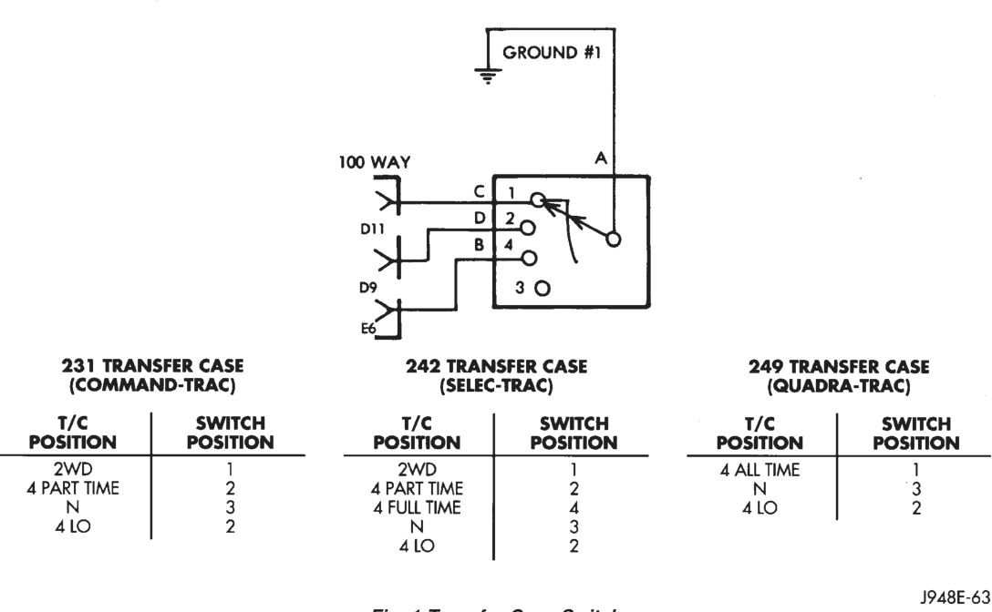
(2) Check the transfer case switch continuity while shifting the transfer case shift lever to the proper positions. The switch continuity should be as shown in (Fig. 1). If OK, go to Step 3. If not OK, replace the faulty switch.
(3) Disconnect and isolate the battery negative cable. Remove the GDM as described in this group. Unplug the GDM connector.
(4) Check the continuity of the circuit for the indicator lamp or wheel lamp that is not functioning between the GDM and transfer case switch connectors. There should be continuity. If OK, go to Step 5. If not OK, repair the open circuit as required.
(5) Replace the bulb for the inoperative indicator lamp or wheel lamp. Plug in the GDM and transfer case connectors. Connect the battery negative cable and check the operation of the inoperative lamp. If OK, discard the faulty bulb. If not OK, replace the faulty GDM.
HEADLAMP HIGH BEAM INDICATOR LAMP
The diagnosis found here addresses an inoperative headlamp high beam indicator lamp condition. If the problem being diagnosed is related to inoperative headlamp high beams, refer to Group 8L - Lamps for diagnosis of the headlamp system. For circuit descriptions and diagrams, refer to 8W-40 - Instrument Cluster in Group 8W - Wiring Diagrams.
WARNING: ON VEHICLES EQUIPPED WITH AIR- BAGS, REFER TO GROUP 8M - PASSIVE RESTRAINT SYSTEMS BEFORE ATTEMPTING STEERING WHEEL, STEERING COLUMN, OR INSTRUMENT PANEL COMPONENT DIAGNOSIS OR SERVICE. FAILURE TO TAKE THE PROPER PRE- CAUTIONS COULD RESULT IN ACCIDENTAL AIR- BAG DEPLOYMENT AND POSSIBLE PERSONAL INJURY.
If the headlamp high beam indicator lamp fails to light during the bulb test (about four seconds after the ignition switch is turned to the On position), replace the headlamp high beam indicator lamp bulb with a known good unit. If the indicator lamp still fails to operate, diagnosis of the lamp, the gauge cluster circuitry, the CCD data bus, and/or the body control module should be performed with a DRB scan tool as described in the proper Body Diagnostic Procedures Manual.
LOW FUEL WARNING LAMP
The diagnosis found here addresses an inoperative low fuel warning lamp condition. If the problem being diagnosed is related to lamp accuracy, be certain to confirm the problem is the with the low fuel warning lamp and not with the fuel gauge circuit. See the diagnosis for the Fuel Gauge in this group. If no fuel gauge problem is found, the following procedure will help to identify a faulty low fuel warning lamp circuit. For circuit descriptions and diagrams, refer to 8W-40 - Instrument Cluster in Group 8W - Wiring Diagrams.
WARNING: ON VEHICLES EQUIPPED WITH AIR- BAGS, REFER TO GROUP 8M - PASSIVE RESTRAINT SYSTEMS BEFORE ATTEMPTING STEERING WHEEL, STEERING COLUMN, OR INSTRUMENT PANEL COMPONENT DIAGNOSIS OR SERVICE. FAILURE TO TAKE THE PROPER PRE- CAUTIONS COULD RESULT IN ACCIDENTAL AIR- BAG DEPLOYMENT AND POSSIBLE PERSONAL INJURY.
If the low fuel warning lamp fails to light during the bulb test (about four seconds after the ignition switch is turned to the On position), replace the low fuel warning lamp bulb with a known good unit. If the indicator lamp still fails to operate, diagnosis of the lamp, the gauge cluster circuitry, the CCD data bus, and/or the body control module should be performed with a DRB scan tool as described in the proper Body Diagnostic Procedures Manual. Diagnosis of the fuel gauge sending unit and circuit, and/or the powertrain control module should be performed with a DRB scan tool as described in the proper Powertrain Diagnostic Procedures Manual.
MALFUNCTION INDICATOR LAMP
The diagnosis found here addresses an inoperative malfunction indicator lamp condition. If the lamp comes on and stays on with the engine running, refer to Group 14 - Fuel System for diagnosis. For circuit descriptions and diagrams, refer to 8W-40 - Instrument Cluster in Group 8W - Wiring Diagrams.
WARNING: ON VEHICLES EQUIPPED WITH AIR- BAGS, REFER TO GROUP 8M - PASSIVE RESTRAINT SYSTEMS BEFORE ATTEMPTING STEERING WHEEL, STEERING COLUMN, OR INSTRUMENT PANEL COMPONENT DIAGNOSIS OR SERVICE. FAILURE TO TAKE THE PROPER PRE- CAUTIONS COULD RESULT IN ACCIDENTAL AIR- BAG DEPLOYMENT AND POSSIBLE PERSONAL INJURY.
If the malfunction indicator lamp fails to light during the bulb test (about three seconds after the ignition switch is turned to the On position), replace the malfunction indicator lamp bulb with a known good unit. If the indicator lamp still fails to operate, diagnosis of the lamp, the gauge cluster circuitry, and/or the CCD data bus should be performed with a DRB scan tool as described in the proper Body Diagnostic Procedures Manual. Diagnosis of the powertrain control module should be performed with a DRB scan tool as described in the proper Powertrain Diagnostic Procedures Manual.
SEAT BELT REMINDER LAMP
The diagnosis found here addresses an inoperative seat belt reminder lamp condition. If the lamp comes on and flashes following its display function (for about seven seconds after the ignition switch is turned to the On position), refer to the diagnosis for the airbag indicator lamp in this group. For circuit descriptions and diagrams, refer to 8W-40 - Instrument Cluster in Group 8W - Wiring Diagrams.
WARNING: ON VEHICLES EQUIPPED WITH AIR- BAGS, REFER TO GROUP 8M - PASSIVE RESTRAINT SYSTEMS BEFORE ATTEMPTING STEERING WHEEL, STEERING COLUMN, OR INSTRUMENT PANEL COMPONENT DIAGNOSIS OR SERVICE. FAILURE TO TAKE THE PROPER PRE- CAUTIONS COULD RESULT IN ACCIDENTAL AIR- BAG DEPLOYMENT AND POSSIBLE PERSONAL INJURY.
If the seat belt reminder lamp fails to light during its display function, replace the seat belt reminder lamp bulb with a known good unit. If the reminder lamp still fails to operate, diagnosis of the lamp, and/or the gauge cluster circuitry should be performed with a DRB scan tool as described in the proper Body Diagnostic Procedures Manual.
TURN SIGNAL INDICATOR LAMPS
The diagnosis found here addresses an inoperative turn signal indicator lamp condition. For any other turn signal problem, refer to Group 8J - Turn Signal and Hazard Warning Systems for diagnosis. If no turn signal or hazard warning system problem is found, the following procedure will help locate a short or open in the indicator lamp circuit. For circuit descriptions and diagrams, refer to 8W-40 - Instrument Cluster and 8W-50 - Front Lighting in Group 8W - Wiring Diagrams.
WARNING: ON VEHICLES EQUIPPED WITH AIR- BAGS, REFER TO GROUP 8M - PASSIVE RESTRAINT SYSTEMS BEFORE ATTEMPTING STEERING WHEEL, STEERING COLUMN, OR INSTRUMENT PANEL COMPONENT DIAGNOSIS OR SERVICE. FAILURE TO TAKE THE PROPER PRE- CAUTIONS COULD RESULT IN ACCIDENTAL AIR- BAG DEPLOYMENT AND POSSIBLE PERSONAL INJURY.
(1) Disconnect and isolate the battery negative cable. Remove the instrument cluster bezel and the cluster assembly as described in this group.
(2) Connect the battery negative cable. Activate the hazard warning system by depressing the hazard warning switch. Check for battery voltage at the inoperative (right or left) turn signal indicator lamp circuit cavity of the cluster connector. There should be a switching (on and off) battery voltage signal. If OK, replace the faulty (right or left) indicator bulb. If not OK, repair the open circuit to the turn signal (multi-function) switch as required.
VEHICLE INFORMATION CENTER
The Vehicle Information Center (VIC) has a number of display functions and features. The diagnosis found here addresses only those VIC messages and functions that are controlled by hard wired inputs. To diagnose any internally controlled VIC function or feature, or any that are enabled by inputs on the CCD data bus network, use a DRB scan tool and the proper Body Diagnostic Procedures Manual. Refer to 8W-46 - Message Center in Group 8W - Wiring Diagrams.
COOLANT LEVEL LOW/COOLANT SENSOR BAD
If the problem being diagnosed is related to lamp accuracy, be certain to confirm that the problem is with the lamp and sensor and not with the engine coolant level. The actual engine coolant level should be checked before you proceed with lamp and sensor diagnosis. Refer to 8W-46 - Message Center in Group 8W - Wiring Diagrams for complete circuit descriptions and diagrams.
WARNING: ON VEHICLES EQUIPPED WITH AIR- BAGS, REFER TO GROUP 8M - PASSIVE RESTRAINT SYSTEMS BEFORE ATTEMPTING STEERING WHEEL, STEERING COLUMN, OR INSTRUMENT PANEL COMPONENT DIAGNOSIS OR SERVICE. FAILURE TO TAKE THE PROPER PRE- CAUTIONS COULD RESULT IN ACCIDENTAL AIR- BAG DEPLOYMENT AND POSSIBLE PERSONAL INJURY.
(1) Unplug the coolant level sensor connector on the coolant reserve bottle. Check for continuity between the ground circuit cavity of the connector and a good ground. There should be continuity. If OK, go to Step 2. If not OK, repair the open circuit as required.
(2) With the engine coolant at the proper level, check the resistance between the two terminals of the coolant level sensor. The resistance should be 3000 to 3500 ohms. If OK, go to Step 3. If not OK, replace the faulty sensor.
(3) Disconnect and isolate the battery negative cable. Remove the VIC module as described in this group. Unplug the VIC module connector. Check for continuity between the engine coolant level switch sense circuit cavity of the VIC connector and a good ground. There should be no continuity. If OK, go to Step 4. If not OK, repair the short circuit as required.
(4) Check for continuity between the engine coolant level switch sense circuit cavities of the VIC connector and the engine coolant level sensor connector. If OK, replace the faulty VIC module. If not OK, repair the open circuit as required.
FOUR-WHEEL DRIVE DISPLAY AND INDICATORS/SERVICE 4WD SWITCH
WARNING: ON VEHICLES EQUIPPED WITH AIRBAGS, REFER TO GROUP 8M - PASSIVE RESTRAINT SYS- TEMS BEFORE ATTEMPTING STEERING WHEEL, STEERING COLUMN, OR INSTRUMENT PANEL COM- PONENT DIAGNOSIS OR SERVICE. FAILURE TO TAKE THE PROPER PRECAUTIONS COULD RESULT IN ACCIDENTAL AIRBAG DEPLOYMENT AND POSSIBLE PERSONAL INJURY.
(1) Unplug the connector at the transfer case switch. Check for continuity between the ground circuit cavity of the transfer case switch connector and a good ground. There should be continuity. If OK, go to Step 2. If not OK, repair the open circuit as required.
(2) Check the transfer case switch continuity while shifting the transfer case shift lever to the proper positions. The switch continuity should be as shown in (Fig. 2). If OK, go to Step 3. If not OK, replace the faulty switch.
(3) Disconnect and isolate the battery negative cable. Remove the VIC module as described in this group. Unplug the VIC module connector.
(4) Locate two pairs of connectors located in the wire harness leading to the VIC module. The connectors should be taped back to the harness. One pair of connectors are black with a single cavity. The other pair are red with two cavities. If the vehicle has the Quadra-Trac 4WD transfer case, only the red connectors should be joined. If the vehicle has the Command-Trac or Selec-Trac 4WD transfer case, only the black connectors should be joined. In all cases, only one pair of connectors should be joined. If OK, go to Step 5. If not OK, correct the connections as required.
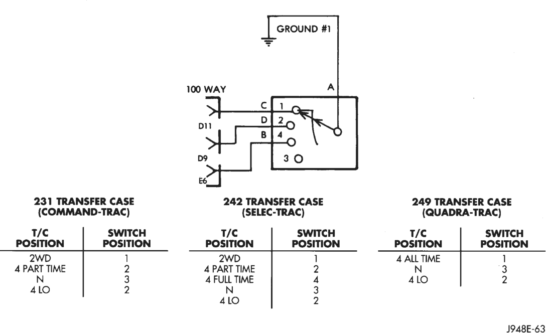
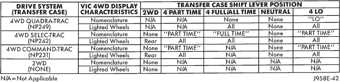
Fig. 3 VIC 4WD Display Characteristics
(5) Refer to the VIC 4WD Display Characteristics chart (Fig. 3). Check the continuity of the circuit for the indicator lamp or wheel lamp that is not functioning between the VIC module and transfer case switch connectors. There should be continuity. If OK, replace the faulty VIC module. If not OK, repair the open circuit as required.
REAR LAMP FAILURE
Refer to the diagnosis for the lamp outage module in Group 8L - Lamps to diagnose this feature of the VIC module. Refer to 8W-46 - Message Center in Group 8W - Wiring Diagrams for complete circuit descriptions and diagrams.
TURN SIGNAL ON
Refer to Group 8J - Turn Signal and Hazard Warning Systems for more information on this feature of the VIC module. The VIC module uses its internal programming, and inputs from the combination flasher on the fused ignition switch output (L5) circuit, and a vehicle speed sensor (distance) message received on the CCD data bus by the powertrain control module to control this message.
If testing of the L5 circuit between the VIC module and the combination flasher in the junction block reveals no problem, use a DRB scan tool and the proper Body Diagnostic Procedures Manual to diagnose the VIC module and the CCD data bus. Refer to 8W-46 - Message Center in Group 8W - Wiring Diagrams for complete circuit descriptions and diagrams.
WASHER LEVEL LOW/WASHER SENSOR BAD
If the problem being diagnosed is related to lamp accuracy, be certain to confirm that the problem is with the lamp and sensor and not with the washer fluid level. The actual fluid level should be checked before you proceed with lamp and sensor diagnosis. Refer to 8W-46 - Message Center in Group 8W - Wiring Diagrams for complete circuit descriptions and diagrams.
WARNING: ON VEHICLES EQUIPPED WITH AIRBAGS, REFER TO GROUP 8M - PASSIVE RESTRAINT SYS-
TEMS BEFORE ATTEMPTING STEERING WHEEL, STEERING COLUMN, OR INSTRUMENT PANEL COM- PONENT DIAGNOSIS OR SERVICE. FAILURE TO TAKE THE PROPER PRECAUTIONS COULD RESULT IN ACCIDENTAL AIRBAG DEPLOYMENT AND POSSIBLE PERSONAL INJURY.
(1) Unplug the washer fluid level sensor connector on the washer reservoir bottle. Check for continuity between the ground circuit cavity of the connector and a good ground. There should be continuity. If OK, go to Step 2. If not OK, repair the open circuit as required.
(2) With the washer fluid at the proper level, check the resistance between the two terminals of the washer fluid level sensor. The resistance should be 3000 to 3500 ohms. If OK, go to Step 3. If not OK, replace the faulty sensor.
(3) Disconnect and isolate the battery negative cable. Remove the VIC module as described in this group. Unplug the VIC module connector. Check for continuity between the washer fluid level sense circuit cavity of the VIC connector and a good ground. There should be no continuity. If OK, go to Step 4. If not OK, repair the short circuit as required.
(4) Check for continuity between the washer fluid level sense circuit cavities of the VIC connector and the washer fluid level sensor connector. If OK, replace the faulty VIC module. If not OK, repair the open circuit as required.
SERVICE PROCEDURES
VEHICLE INFORMATION CENTER
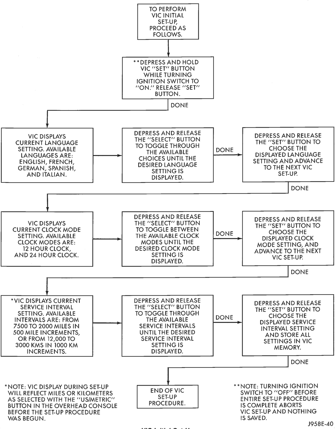
The following flow charts describe the procedures to perform an initial set-up of the Vehicle Information Center (VIC), and how to reset the VIC service reminder or clock settings. It should be noted that the minutes setting of the VIC clock will automatically be synchronized to the minutes setting of the radio clock by a message that the radio sends to the VIC module on the Chrysler Collision Detection (CCD) data bus network. Refer to Group 8F - Audio Systems for more information on this feature.
VIC Initial Set-Up
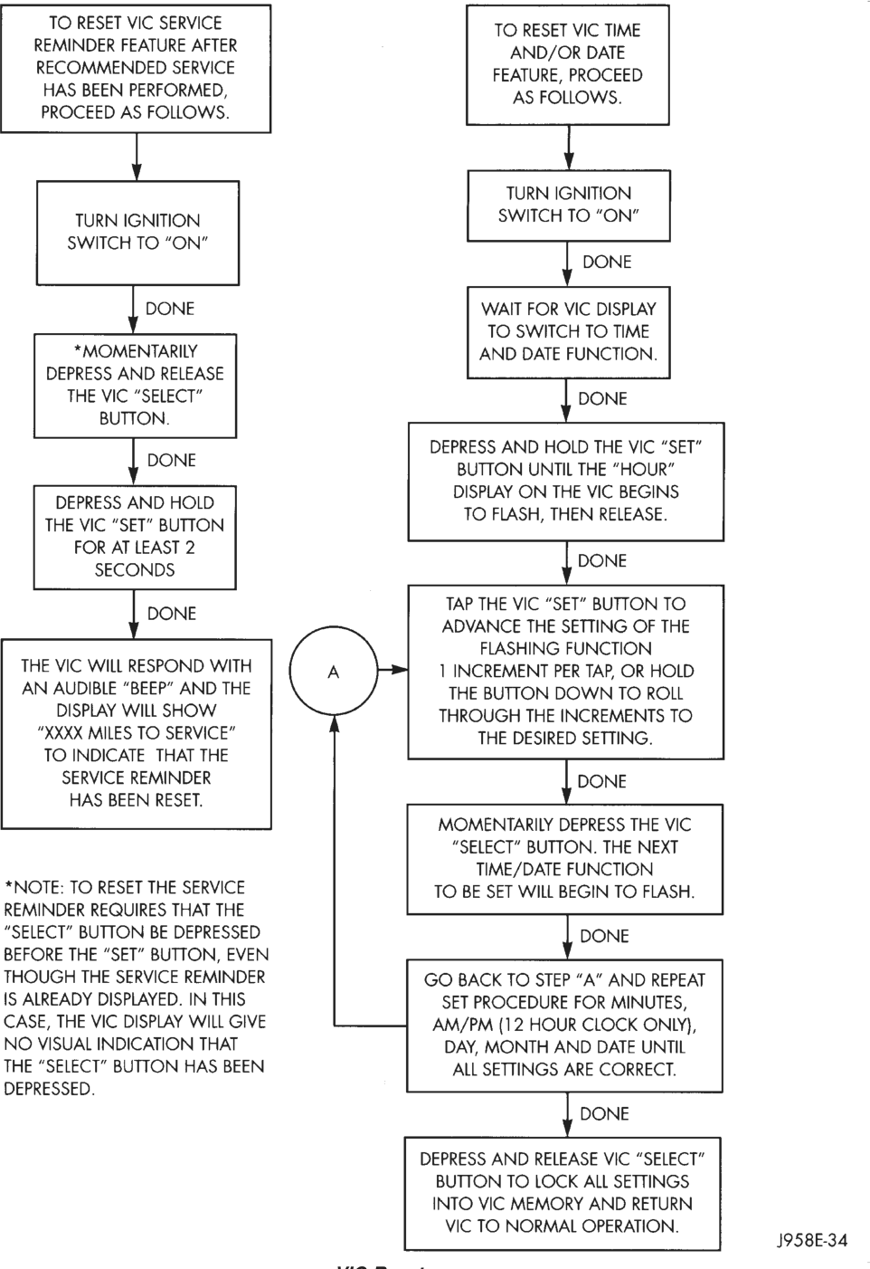
VIC Reset
REMOVAL AND INSTALLATION
SWITCH POD BEZELS
WARNING: ON VEHICLES EQUIPPED WITH AIR- BAGS, REFER TO GROUP 8M - PASSIVE RESTRAINT SYSTEMS BEFORE ATTEMPTING STEERING WHEEL, STEERING COLUMN, OR INSTRUMENT PANEL COMPONENT DIAGNOSIS OR SERVICE. FAILURE TO TAKE THE PROPER PRE- CAUTIONS COULD RESULT IN ACCIDENTAL AIR- BAG DEPLOYMENT AND POSSIBLE PERSONAL INJURY.
Both switch pod bezels are held in place with spring clips and a light snap fit. To remove the bezel from the instrument panel, pry gently around the edges of the bezel using a trim stick or other suitable wide flat-bladed tool. To install the bezel, hold it in position with one hand, then push the bezel firmly into place with the other hand.
KNEE BLOCKER
WARNING: ON VEHICLES EQUIPPED WITH AIR- BAGS, REFER TO GROUP 8M - PASSIVE RESTRAINT SYSTEMS BEFORE ATTEMPTING STEERING WHEEL, STEERING COLUMN, OR INSTRUMENT PANEL COMPONENT DIAGNOSIS OR SERVICE. FAILURE TO TAKE THE PROPER PRE- CAUTIONS COULD RESULT IN ACCIDENTAL AIR- BAG DEPLOYMENT AND POSSIBLE PERSONAL INJURY.
(1) Disconnect and isolate the battery negative cable.
(2) Remove the left and right switch pod bezels as described in this group.
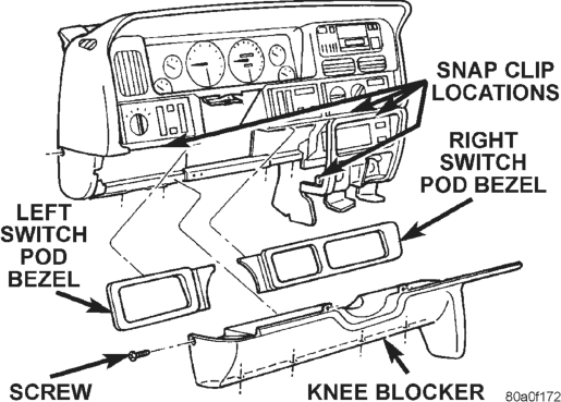
(3) Remove one screw on each side of the steering column on the upper edge of the knee blocker/steering column cover (Fig. 4).
(4) Remove one screw securing the left end of the knee blocker to the instrument panel.
(5) Remove the four screws securing the lower edge of the knee blocker to the lower instrument panel reinforcement.
(6) Using a trim stick or other suitable wide flatbladed tool, gently pry the edges of the knee blocker away from the instrument panel at the locations shown (Fig. 4).
(7) Remove the knee blocker/steering column cover from the vehicle.
(8) Reverse the removal procedures to install.
CLUSTER BEZEL
WARNING: ON VEHICLES EQUIPPED WITH AIR- BAGS, REFER TO GROUP 8M - PASSIVE RESTRAINT SYSTEMS BEFORE ATTEMPTING STEERING WHEEL, STEERING COLUMN, OR INSTRUMENT PANEL COMPONENT DIAGNOSIS OR SERVICE. FAILURE TO TAKE THE PROPER PRE- CAUTIONS COULD RESULT IN ACCIDENTAL AIR- BAG DEPLOYMENT AND POSSIBLE PERSONAL INJURY.
(1) Disconnect and isolate the battery negative cable.
(2) Remove the left and right switch pod bezels as described in this group.
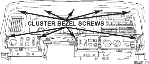
(3) Remove the nine screws securing the cluster bezel to the instrument panel (Fig. 5).
(4) Pull the cluster bezel rearward and move it to the left of the steering wheel to remove it from the vehicle.
(5) Reverse the removal procedures to install.
INSTRUMENT CLUSTER
WARNING: ON VEHICLES EQUIPPED WITH AIR- BAGS, REFER TO GROUP 8M - PASSIVE RESTRAINT SYSTEMS BEFORE ATTEMPTING STEERING WHEEL, STEERING COLUMN, OR INSTRUMENT PANEL COMPONENT DIAGNOSIS OR SERVICE. FAILURE TO TAKE THE PROPER PRE- CAUTIONS COULD RESULT IN ACCIDENTAL AIR- BAG DEPLOYMENT AND POSSIBLE PERSONAL INJURY.
(1) Remove the cluster bezel as described in this group.
(2) Remove the two screws securing each end of the cluster to the instrument panel.
(3) Pull the cluster rearward and remove it from the vehicle.
(4) Reverse the removal procedures to install.
CLUSTER LENS, HOOD, AND MASK
WARNING: ON VEHICLES EQUIPPED WITH AIR- BAGS, REFER TO GROUP 8M - PASSIVE RESTRAINT SYSTEMS BEFORE ATTEMPTING STEERING WHEEL, STEERING COLUMN, OR INSTRUMENT PANEL COMPONENT DIAGNOSIS OR SERVICE. FAILURE TO TAKE THE PROPER PRE- CAUTIONS COULD RESULT IN ACCIDENTAL AIR-
BAG DEPLOYMENT AND POSSIBLE PERSONAL INJURY.
(1) Remove the cluster bezel as described in this group.
(2) Remove the instrument cluster as described in this group.
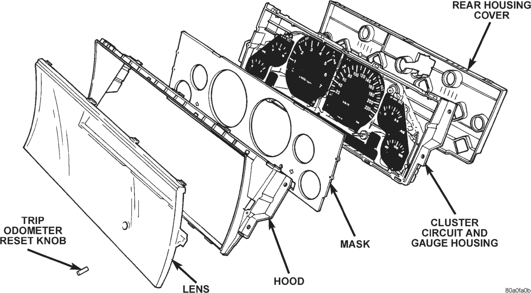
(3) Remove the trip odometer reset knob by pulling it off of the switch stem (Fig. 6).
(4) Depress the snap clips securing the cluster lens to the cluster hood and gently pull the lens away from the hood.
(5) Depress the snap clips securing the cluster hood to the cluster circuit and gauge housing and gently pull the hood away from the housing.
(6) Gently lift the gauge mask away from the locating pins on the front of the cluster circuit and gauge housing.
(7) Reverse the removal procedures to install.
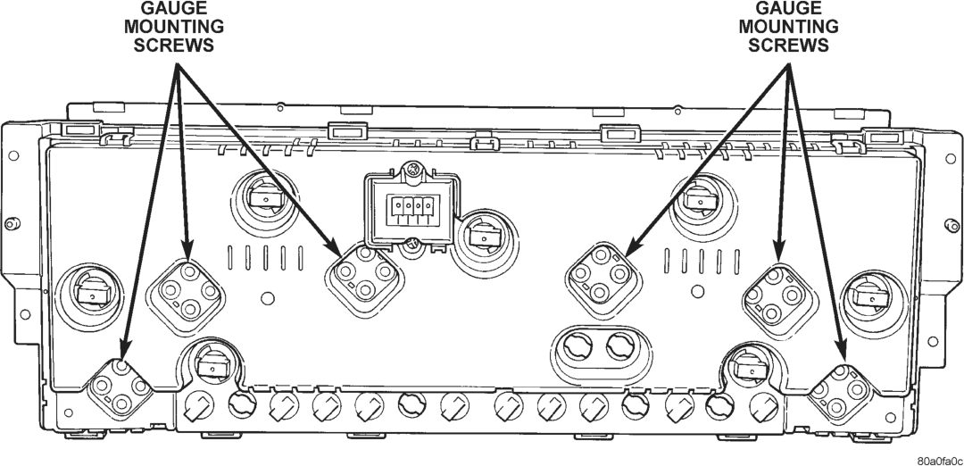
GAUGES
WARNING: ON VEHICLES EQUIPPED WITH AIR- BAGS, REFER TO GROUP 8M - PASSIVE RESTRAINT SYSTEMS BEFORE ATTEMPTING STEERING WHEEL, STEERING COLUMN, OR INSTRUMENT PANEL COMPONENT DIAGNOSIS OR SERVICE. FAILURE TO TAKE THE PROPER PRE- CAUTIONS COULD RESULT IN ACCIDENTAL AIR- BAG DEPLOYMENT AND POSSIBLE PERSONAL INJURY.
(1) Remove the cluster lens, hood, and mask as described in this group.
(2) Remove the retaining screws securing the gauge(s) from the rear of the cluster circuit and gauge housing (Fig. 7).
(3) Remove the gauge(s) from the front of the cluster circuit and gauge housing.
(4) Reverse the removal procedures to install.
CLUSTER BULBS
WARNING: ON VEHICLES EQUIPPED WITH AIR- BAGS, REFER TO GROUP 8M - PASSIVE RESTRAINT SYSTEMS BEFORE ATTEMPTING STEERING WHEEL, STEERING COLUMN, OR INSTRUMENT PANEL COMPONENT DIAGNOSIS OR SERVICE. FAILURE TO TAKE THE PROPER PRE- CAUTIONS COULD RESULT IN ACCIDENTAL AIR- BAG DEPLOYMENT AND POSSIBLE PERSONAL INJURY.
(1) Remove the instrument cluster as described in this group.
(2) Remove the bulb and socket from the rear cluster circuit and gauge housing by using a twisting motion (Fig. 8).
(3) Unplug the bulb from the socket. (4) Reverse the removal procedures to install.
LEFT SWITCH POD
WARNING: ON VEHICLES EQUIPPED WITH AIR- BAGS, REFER TO GROUP 8M - PASSIVE RESTRAINT SYSTEMS BEFORE ATTEMPTING STEERING WHEEL, STEERING COLUMN, OR INSTRUMENT PANEL COMPONENT DIAGNOSIS OR SERVICE. FAILURE TO TAKE THE PROPER PRE- CAUTIONS COULD RESULT IN ACCIDENTAL AIR- BAG DEPLOYMENT AND POSSIBLE PERSONAL INJURY.
(1) Remove the cluster bezel as described in this group.
(2) Remove the two screw securing the left switch pod to the instrument panel (Fig. 9).
(3) Pull the left switch pod out from the instrument panel far enough to unplug the wiring connectors.
(4) Remove the left switch pod from the instrument panel.
(5) Reverse the removal procedures to install.
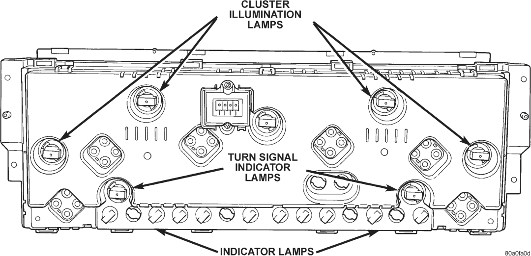
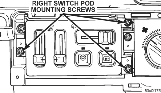
RIGHT SWITCH POD
WARNING: ON VEHICLES EQUIPPED WITH AIR- BAGS, REFER TO GROUP 8M - PASSIVE RESTRAINT SYSTEMS BEFORE ATTEMPTING STEERING WHEEL, STEERING COLUMN, OR INSTRUMENT PANEL COMPONENT DIAGNOSIS OR SERVICE. FAILURE TO TAKE THE PROPER PRE- CAUTIONS COULD RESULT IN ACCIDENTAL AIR- BAG DEPLOYMENT AND POSSIBLE PERSONAL INJURY.
(1) Disconnect and isolate the battery negative cable.
(2) Remove the right switch pod bezel as described in this group.
(3) Remove the three screws securing the right switch pod to the instrument panel (Fig. 10).
(4) Pull the right switch pod out from the instrument panel far enough to unplug the wiring connectors.
(5) Remove the right switch pod from the instrument panel.
(6) Reverse the removal procedures to install.
BODY CONTROL MODULE
WARNING: ON VEHICLES EQUIPPED WITH AIR- BAGS, REFER TO GROUP 8M - PASSIVE RESTRAINT SYSTEMS BEFORE ATTEMPTING STEERING WHEEL, STEERING COLUMN, OR INSTRUMENT PANEL COMPONENT DIAGNOSIS OR SERVICE. FAILURE TO TAKE THE PROPER PRE- CAUTIONS COULD RESULT IN ACCIDENTAL AIR- BAG DEPLOYMENT AND POSSIBLE PERSONAL INJURY.
(1) Remove the knee blocker/steering column cover as described in this group.
(2) Remove the four screws securing the body control module to the instrument panel armature (Fig. 11).
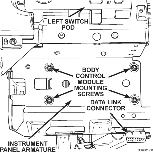
(3) Move the body control module towards the steering column far enough to unplug the three wiring connectors.
(4) Remove the body control module. (5) Reverse the removal procedures to install.
LOWER RIGHT INSTRUMENT PANEL MODULE
WARNING: ON VEHICLES EQUIPPED WITH AIR- BAGS, REFER TO GROUP 8M - PASSIVE RESTRAINT SYSTEMS BEFORE ATTEMPTING STEERING WHEEL, STEERING COLUMN, OR INSTRUMENT PANEL COMPONENT DIAGNOSIS OR SERVICE. FAILURE TO TAKE THE PROPER PRE- CAUTIONS COULD RESULT IN ACCIDENTAL AIR- BAG DEPLOYMENT AND POSSIBLE PERSONAL INJURY.
(1) Remove the knee blocker/steering column cover as described in this group.
(2) Remove the two screws securing the top of the instrument panel center bezel above the graphic display module/vehicle information center.
(3) Remove the ash receiver and remove the two screws in the back of the ash receiver opening of the center bezel.
(4) Remove the courtesy lamp under the right end of the instrument panel.
(5) Open the right front door and remove the screw in the right end of the instrument panel.
(6) Remove the four screws in the glove box hinge on the bottom edge of the lower right instrument panel module.
(7) Open the glove box door and remove the four screws on the upper edge of the glove box opening in the lower right instrument panel module.
(8) Lower the lower right instrument panel far enough to unplug the wiring connectors for the glove box lamp/switch, the cigar lighter/lamp, and the power outlet. Also remove the bulb and socket as a unit from the ash receiver lamp hood.
(9) Remove the lower right instrument panel module from the vehicle.
(10) Reverse the removal procedures to install.
GRAPHIC DISPLAY MODULE/VEHICLE INFORMATION CENTER
WARNING: ON VEHICLES EQUIPPED WITH AIR- BAGS, REFER TO GROUP 8M - PASSIVE RESTRAINT SYSTEMS BEFORE ATTEMPTING STEERING WHEEL, STEERING COLUMN, OR INSTRUMENT PANEL COMPONENT DIAGNOSIS OR SERVICE. FAILURE TO TAKE THE PROPER PRE- CAUTIONS COULD RESULT IN ACCIDENTAL AIR- BAG DEPLOYMENT AND POSSIBLE PERSONAL INJURY.
(1) Remove the lower right instrument panel module as described in this group.
(2) Remove the three screws securing the graphic display module/vehicle information center to the instrument panel (Fig. 12).
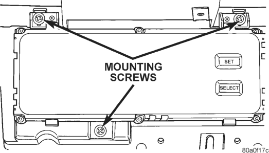
Center Remove/Install
(3) Pull the unit out from the instrument panel far enough to unplug the wiring connector.
(4) Remove the graphic display module/vehicle information center from the instrument panel.
(5) Reverse the removal procedures to install.
GLOVE BOX LAMP AND SWITCH
WARNING: ON VEHICLES EQUIPPED WITH AIR- BAGS, REFER TO GROUP 8M - PASSIVE RESTRAINT SYSTEMS BEFORE ATTEMPTING STEERING WHEEL, STEERING COLUMN, OR INSTRUMENT PANEL COMPONENT DIAGNOSIS OR SERVICE. FAILURE TO TAKE THE PROPER PRE- CAUTIONS COULD RESULT IN ACCIDENTAL AIR- BAG DEPLOYMENT AND POSSIBLE PERSONAL INJURY.
(1) Remove the lower right instrument panel module as described in this group.
(2) From the back side of the lower right instrument panel module, squeeze the retaining tabs on the glove box lamp and switch housing together and push the unit out through the front of the mounting hole in the module (Fig. 13).
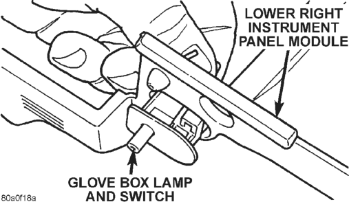
(3) To install the glove box lamp and switch unit, insert the unit through the mounting hole from the front of the lower right instrument panel module and push in on the unit firmly, until the retaining tabs snap into place.
GLOVE BOX LATCH STRIKER
WARNING: ON VEHICLES EQUIPPED WITH AIR- BAGS, REFER TO GROUP 8M - PASSIVE RESTRAINT SYSTEMS BEFORE ATTEMPTING STEERING WHEEL, STEERING COLUMN, OR INSTRUMENT PANEL COMPONENT DIAGNOSIS OR SERVICE. FAILURE TO TAKE THE PROPER PRE- CAUTIONS COULD RESULT IN ACCIDENTAL AIR- BAG DEPLOYMENT AND POSSIBLE PERSONAL INJURY.
(1) Remove the lower right instrument panel module as described in this group.
(2) From the top of the lower right instrument panel module, straighten the two mounting tabs (Fig. 14).
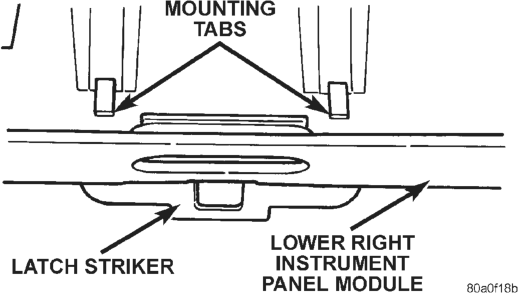
(3) Remove the latch striker from the upper glove box opening.
(4) To install the latch striker, insert the mounting tabs through the slots in the upper glove box opening and bend the tabs over from the top of the lower right instrument panel module.
CIGAR LIGHTER
WARNING: ON VEHICLES EQUIPPED WITH AIR- BAGS, REFER TO GROUP 8M - PASSIVE RESTRAINT SYSTEMS BEFORE ATTEMPTING STEERING WHEEL, STEERING COLUMN, OR INSTRUMENT PANEL COMPONENT DIAGNOSIS OR SERVICE. FAILURE TO TAKE THE PROPER PRE- CAUTIONS COULD RESULT IN ACCIDENTAL AIR- BAG DEPLOYMENT AND POSSIBLE PERSONAL INJURY.
(1) Disconnect and isolate the battery negative cable.
(2) Pull the cigar lighter knob and element out of the cigar lighter base.
(3) Look inside the cigar lighter base and note the position of the retaining bosses (Fig. 15).
(4) Insert a pair of external snap ring pliers into the cigar lighter base and engage the tips of the pliers with the retaining bosses.
(5) Squeeze the pliers to disengage the retaining bosses from the base, and using a gentle rocking motion pull the pliers and the cigar lighter base out of the light ring/retainer.
(6) Remove the pliers from the cigar lighter base and unplug the wiring connector.
(7) Remove the cigar lighter light ring/retainer from the instrument panel and unplug the wiring connector.
(8) Reverse the removal procedures to install.
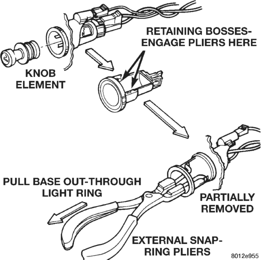
POWER OUTLET
WARNING: ON VEHICLES EQUIPPED WITH AIR- BAGS, REFER TO GROUP 8M - PASSIVE RESTRAINT SYSTEMS BEFORE ATTEMPTING STEERING WHEEL, STEERING COLUMN, OR INSTRUMENT PANEL COMPONENT DIAGNOSIS OR SERVICE. FAILURE TO TAKE THE PROPER PRE- CAUTIONS COULD RESULT IN ACCIDENTAL AIR- BAG DEPLOYMENT AND POSSIBLE PERSONAL INJURY.
(1) Remove the lower right instrument panel module as described in this group.
(2) From the rear of the instrument panel center bezel, unscrew the power outlet shell clamp from the power outlet base.
(3) From the front of the instrument panel center bezel, remove the power outlet base.
(4) Reverse the removal procedures to install.
POWER OUTLET DOOR
(1) Insert a trim stick or other suitable wide flatbladed tool between the side of the power outlet housing in the instrument panel center bezel and the upper pivot area of the power outlet door.
(2) Pry gently against the upper pivot area of the power outlet door until the door pivot pin clears the pivot receptacle in the instrument panel center bezel.
(3) Pull the power outlet door out of the power outlet housing.
(4) To install the door, insert one of the pivot pins into a pivot receptacle in the center bezel and twist the door gently until the pivot pin on the opposite side of the door snaps into the other pivot receptacle.
INSTRUMENT PANEL CENTER BEZEL
WARNING: ON VEHICLES EQUIPPED WITH AIR- BAGS, REFER TO GROUP 8M - PASSIVE RESTRAINT SYSTEMS BEFORE ATTEMPTING STEERING WHEEL, STEERING COLUMN, OR INSTRUMENT PANEL COMPONENT DIAGNOSIS OR SERVICE. FAILURE TO TAKE THE PROPER PRE- CAUTIONS COULD RESULT IN ACCIDENTAL AIR- BAG DEPLOYMENT AND POSSIBLE PERSONAL INJURY.
(1) Remove the lower right instrument panel module as described in this group.
(2) From the rear of the lower right instrument panel module, remove the two screws securing the center bezel to the lower right module (Fig. 16).
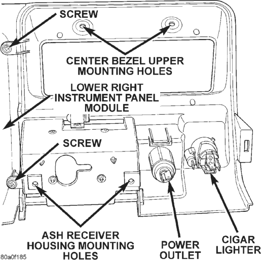
(3) Reverse the removal procedures to install.
GLOVE BOX
WARNING: ON VEHICLES EQUIPPED WITH AIR- BAGS, REFER TO GROUP 8M - PASSIVE RESTRAINT SYSTEMS BEFORE ATTEMPTING STEERING WHEEL, STEERING COLUMN, OR INSTRUMENT PANEL COMPONENT DIAGNOSIS OR SERVICE. FAILURE TO TAKE THE PROPER PRE- CAUTIONS COULD RESULT IN ACCIDENTAL AIR- BAG DEPLOYMENT AND POSSIBLE PERSONAL INJURY.
(1) Disconnect and isolate the battery negative cable.
(2) Drill out the two rivets securing the glove box hinge to the lower right instrument panel module (Fig. 17).
NOTE: The rivets are used to ease assembly during the manufacturing process, but do not require replacement following service.
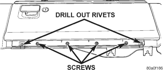
(3) Remove the four screws securing the glove box hinge to the instrument panel armature.
(4) Release the glove box latch and remove the glove box from the lower right instrument panel module glove box opening.
(5) Reverse the removal procedures to install.
GLOVE BOX COMPONENTS
The glove box bezel is the only component of the glove box that can be serviced without glove box removal. All other components will require the glove box to be removed from the lower right instrument panel module as described in this group.
GLOVE BOX BEZEL
(1) Open the glove box. (2) Remove the two screws securing the bezel at the top of the glove box inner door panel (Fig. 18).
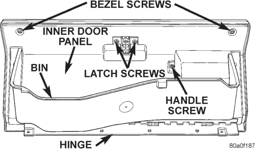
(3) Pull the bezel firmly away from the outside glove box door. There is double-faced adhesive tape between the bezel and the outer door panel.
(4) Reverse the removal procedures to install.
GLOVE BOX HINGE
(1) Remove the glove box. (2) Remove the screws securing the glove box hinge to the glove box door.
(3) Remove the glove box hinge. (4) Reverse the removal procedures to install.
GLOVE BOX BIN
(1) Remove the glove box. (2) Remove the glove box hinge as described in this group.
(3) Remove the screws securing each side of the bin to the glove box door.
(4) Remove the glove box bin. (5) Reverse the removal procedures to install.
GLOVE BOX LATCH AND HANDLE
(1) Remove the glove box. (2) Remove the glove box hinge and bin as described in this group.
(3) Remove the two bezel screws, two latch screws, and one handle screw from the inner door panel.
(4) Remove the inner panel from the glove box door.
(5) Remove the other glove box latch handle screw (Fig. 19).
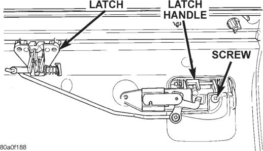
(6) Remove the latch and handle from the glove box door as a unit.
(7) Reverse the removal procedures to install.
GLOVE BOX LOCK CYLINDER
(1) Remove the glove box latch and handle as described in this group.
(2) Insert the key into the glove box lock cylinder. (3) Insert a small screwdriver into the retaining tumbler release slot and depress the retaining tumbler (Fig. 20).
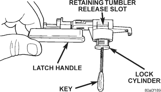
(4) Pull the lock cylinder out of the latch handle by using a gentle twisting and pulling action on the key.
(5) Reverse the removal procedures to install.
COWL TOP TRIM PANEL
WARNING: ON VEHICLES EQUIPPED WITH AIR- BAGS, REFER TO GROUP 8M - PASSIVE RESTRAINT SYSTEMS BEFORE ATTEMPTING STEERING WHEEL, STEERING COLUMN, OR INSTRUMENT PANEL COMPONENT DIAGNOSIS OR SERVICE. FAILURE TO TAKE THE PROPER PRE- CAUTIONS COULD RESULT IN ACCIDENTAL AIR- BAG DEPLOYMENT AND POSSIBLE PERSONAL INJURY.
(1) Disconnect and isolate the battery negative cable.
(2) Using a wide flat-bladed tool such as a trim stick, pry the cowl top trim panel off of the instrument panel top pad (Fig. 21).
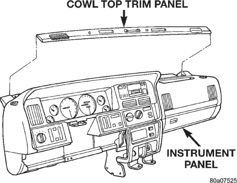
(3) Pull the panel up far enough to unplug the wiring connector for the solar sensor, or to remove the solar sensor from the cowl top trim between the right and center defroster outlets, if so equipped.
(4) Remove the cowl top trim panel from the vehicle.
(5) Reverse the removal procedures to install.
INSTRUMENT PANEL TOP PAD
WARNING: ON VEHICLES EQUIPPED WITH AIR- BAGS, REFER TO GROUP 8M - PASSIVE RESTRAINT SYSTEMS BEFORE ATTEMPTING STEERING WHEEL, STEERING COLUMN, OR INSTRUMENT PANEL COMPONENT DIAGNOSIS OR SERVICE. FAILURE TO TAKE THE PROPER PRE- CAUTIONS COULD RESULT IN ACCIDENTAL AIR- BAG DEPLOYMENT AND POSSIBLE PERSONAL INJURY.
(1) Disconnect and isolate the battery negative cable.
(2) Remove the switch pod bezels, the cluster bezel, the knee blocker, the lower right instrument panel module, and the cowl top trim panel. See the procedures in this group.
(3) If so equipped, remove the auto headlamp light sensor/vehicle theft security system lamp mounting screw near the left defroster duct outlet and move it for clearance of the instrument panel top pad.
(4) Remove all of the screws around the perimeter of the instrument panel top pad, which secure the top pad to the instrument panel armature.
(5) Lift the top pad off of the instrument panel armature and remove it from the vehicle.
(6) Reverse the removal procedures to install.
JUNCTION BLOCK
WARNING: ON VEHICLES EQUIPPED WITH AIR- BAGS, REFER TO GROUP 8M - PASSIVE RESTRAINT SYSTEMS BEFORE ATTEMPTING STEERING WHEEL, STEERING COLUMN, OR INSTRUMENT PANEL COMPONENT DIAGNOSIS OR SERVICE. FAILURE TO TAKE THE PROPER PRE- CAUTIONS COULD RESULT IN ACCIDENTAL AIR- BAG DEPLOYMENT AND POSSIBLE PERSONAL INJURY.
(1) Disconnect and isolate the battery negative cable.
(2) Remove the fuse access panel by unsnapping it from the right cowl side trim panel.
(3) Remove the nut securing the right cowl side trim to the junction block stud (Fig. 22).
(4) Remove the two screws securing the right cowl side trim to the right front door opening trim.
(5) Remove the right cowl side trim panel.
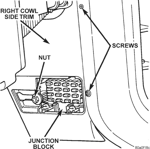
(6) Unplug all of the wiring connectors from the junction block cavities.
(7) Remove the junction block mounting bolt (Fig. 23).
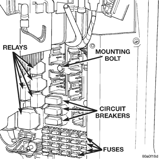
(8) Lift upwards on the junction block to remove its slide-tab mount off of the mounting bracket on the right cowl side panel.
(9) Remove the junction block from the vehicle. (10) Reverse the removal procedures to install.
INSTRUMENT PANEL ASSEMBLY
WARNING: ON VEHICLES EQUIPPED WITH AIR- BAGS, REFER TO GROUP 8M - PASSIVE RESTRAINT SYSTEMS BEFORE ATTEMPTING STEERING WHEEL, STEERING COLUMN, OR INSTRUMENT PANEL COMPONENT DIAGNOSIS OR SERVICE. FAILURE TO TAKE THE PROPER PRE- CAUTIONS COULD RESULT IN ACCIDENTAL AIR- BAG DEPLOYMENT AND POSSIBLE PERSONAL INJURY.
(1) Disconnect and isolate the battery negative cable.
(2) Remove the left and right switch pod bezels as described in this group.
(3) Remove the knee blocker as described in this group.
(4) Remove the two bolts securing the lower instrument panel reinforcement to the instrument panel armature and remove the reinforcement (Fig. 24). (5) Remove the upper and lower steering column shrouds. Refer to Group 19 - Steering for the procedures.
(6) Unplug all of the wiring connectors on the steering column-mounted components and switches.
(7) Remove the three nuts securing the steering column toe plate at the base of the steering column.
(8) Remove the two nuts securing the steering column mounting bracket to the studs on the steering column and brake pedal support and lower the steering column to the floor.
(9) Remove the right and left cowl side trim panels. Refer to Group 23 - Body Components for the procedures.
(10) Unplug the instrument panel to body wiring connector under the left end of the instrument panel.
(11) Unplug the brake lamp switch wiring connector.
(12) Unplug the instrument panel to heater-A/C housing vacuum connector (manual temperature control only) and wiring connector located under the right side of the instrument panel.
(13) Unplug the radio antenna coaxial cable connector near the right cowl side panel.
(14) Unplug all of the instrument panel wiring connectors from the junction block on the right cowl side panel.
(15) Disconnect the in-car temperature sensor aspirator hose at the coupling near the right side of the transmission floor tunnel, if so equipped.
(16) Remove the ash receiver and then remove the screw in the back of the ash receiver housing securing the instrument panel armature to the heater-A/C housing.
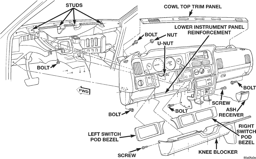
(17) Pull back the floor carpet on the transmission floor tunnel from the base of the instrument panel center bezel and remove the two bolts securing the instrument panel center bracket to the floor.
(18) Remove the two bolts securing the instrument panel center bracket to the left side of the transmission floor tunnel.
(19) Remove the bolt securing the instrument panel armature to the steering column and brake pedal support.
(20) Remove the two bolts securing the ends of the instrument panel armature to the cowl side panels.
(21) Remove the cowl top trim panel as described in this group.
(22) Remove the two bolts securing the ends of the instrument panel armature to the windshield fence.
(23) Remove the four nuts securing the top of the instrument panel armature to the studs on the windshield fence.
(24) With the aid of an assistant, lift the instrument panel off of the windshield fence studs and maneuver the assembly out of the passenger’s side front door.
(25) Reverse the removal procedures to install. Tighten the mounting hardware as follows:
• Instrument panel to windshield fence bolts and nuts - 5 N·m (45 in. lbs.)
• Instrument panel to cowl side panel bolts - 12 N·m (105 in. lbs.)
• Instrument panel to steering column support bolt - 12 N·m (105 in. lbs.)
• Knee blocker mounting screws - 2.2 N·m (20 in. lbs.).