Horn Systems — 1996 Jeep Grand Cherokee ZJ Service Manual
Pages 370–373 · 4 pages · 0 words repaired
The horn system is one of the outputs of the BCM. The BCM is programmed to energize the horn relay in response to certain inputs from the Vehicle Theft Security System (VTSS) system or the Remote Keyless Entry (RKE) system. Refer to Group 8P - Power Lock Systems for more information on the RKE system. Refer to Group 8Q - Vehicle Theft/Security Systems for more information on the VTSS system.
The BCM is mounted under the left end of the instrument panel, behind the instrument panel support armature and below the left switch pod. Refer to Group 8E - Instrument Panel Systems for removal and installation procedures. For diagnosis of the BCM or the CCD data bus, refer to the proper Body Diagnostic Procedures Manual. The BCM can only be serviced by an authorized repair station. Refer to the Warranty Policies and Procedures Manual for a listing of authorized repair stations.
DIAGNOSIS AND TESTING
HORN RELAY
For circuit descriptions and diagrams, refer to 8W-41 - Horns/Cigar Lighter in Group 8W - Wiring Diagrams.
WARNING: ON VEHICLES EQUIPPED WITH AIR- BAGS, REFER TO GROUP 8M - PASSIVE RESTRAINT SYSTEMS BEFORE ATTEMPTING STEERING WHEEL, STEERING COLUMN, OR INSTRUMENT PANEL COMPONENT DIAGNOSIS OR SERVICE. FAILURE TO TAKE THE PROPER PRE- CAUTIONS COULD RESULT IN ACCIDENTAL AIR- BAG DEPLOYMENT AND POSSIBLE PERSONAL INJURY.
RELAY TESTS
The horn relay is located in the Power Distribution Center (PDC) in the engine compartment. Refer to the PDC label for horn relay identification and location.
Remove the horn relay from the PDC as described in this group to perform the following tests:
(1) A relay in the de-energized position should have continuity between terminals 87A and 30, and no continuity between terminals 87 and 30. If OK, go to Step 2. If not OK, replace the faulty relay.
(2) Resistance between terminals 85 and 86 (electromagnet) should be 7565 ohms. If OK, go to Step 3. If not OK, replace the faulty relay. (3) Connect a battery to terminals 85 and 86. There should now be continuity between terminals 30 and 87, and no continuity between terminals 87A and 30. If OK, see the Relay Circuit Test in this group. If not OK, replace the faulty relay.
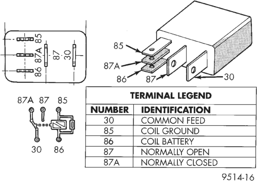
Horn Relay
RELAY CIRCUIT TESTS
(1) The relay common feed terminal cavity (30) is connected to battery voltage and should be hot at all times. If OK, go to Step 2. If not OK, repair the open circuit to the PDC fuse as required.
(2) The relay normally closed terminal (87A) is connected to terminal 30 in the de-energized position, but is not used for this application. Go to Step 3.
(3) The relay normally open terminal (87) is connected to the common feed terminal (30) in the energized position. This terminal supplies battery voltage to the horn(s). There should be continuity between the cavity for relay terminal 87 and the horn(s) feed terminal(s) at all times. If OK, go to Step 4. If not OK, repair the open circuit to the horn(s) as required.
(4) The coil battery terminal (86) is connected to the electromagnet in the relay. It is connected to battery voltage and should be hot at all times. Check for battery voltage at the cavity for relay terminal 86. If OK, go to Step 5. If not OK, repair the open circuit to the PDC fuse as required.
(5) The coil ground terminal (85) is connected to the electromagnet in the relay. It is grounded through the horn switch when the horn switch is depressed. It can also be grounded by the body control module in response to inputs from the vehicle theft alarm or remote keyless entry systems. Check for continuity to ground at the cavity for relay terminal 85. There should be continuity with the horn switch depressed, and no continuity with the horn switch released. If not OK, see the diagnosis for the Horn Switch in this group.
HORN SWITCH
For circuit descriptions and diagrams, refer to 8W-41 - Horns/Cigar Lighter in Group 8W - Wiring Diagrams.
WARNING: ON VEHICLES EQUIPPED WITH AIR- BAGS, REFER TO GROUP 8M - PASSIVE RESTRAINT SYSTEMS BEFORE ATTEMPTING STEERING WHEEL, STEERING COLUMN, OR INSTRUMENT PANEL COMPONENT DIAGNOSIS OR SERVICE. FAILURE TO TAKE THE PROPER PRE- CAUTIONS COULD RESULT IN ACCIDENTAL AIR- BAG DEPLOYMENT AND POSSIBLE PERSONAL INJURY.
(1) Disconnect and isolate the battery negative cable. Remove the lower steering column cover/knee blocker. Check for continuity between the metal steering column jacket and a good ground. There should be continuity. If OK, go to Step 2. If not OK, refer to Group 19 - Steering and check for proper installation of the steering column ground clip.
(2) Remove the driver’s airbag module. Unplug the horn switch wire connector. Unplug the body control module connector B (white). Remove the horn relay from the Power Distribution Center (PDC). Check for continuity between the steering column half of the horn switch wire connector and a good ground. There should be no continuity. If OK, go to Step 3. If not OK, repair the short circuit as required.
(3) Check for continuity between the steering column half of the horn switch wire connector and the horn relay control circuit cavity in the PDC. There should be continuity. If OK, go to Step 4. If not OK, repair the open circuit as required.
(4) Check for continuity between the two horn switch wires on the airbag module. There should be no continuity. If OK, go to Step 5. If not OK, replace the faulty horn switch.
(5) Depress the center of the airbag module cover and check for continuity between the two horn switch wires. There should be continuity. If not OK, replace the faulty horn switch.
HORN
For circuit descriptions and diagrams, refer to 8W-41 - Horns/Cigar Lighter in Group 8W - Wiring Diagrams.
(1) Disconnect the horn wiring connector. Measure the resistance between the ground circuit cavity of the horn connector and a good ground. There should be zero ohms resistance. If OK, go to Step 2. If not OK, repair the faulty horn ground circuit as required.
(2) Depress the horn switch. There should be battery voltage at the horn relay output circuit cavity of the horn connector. If OK, replace the faulty horn. If not OK, repair the open circuit to the horn relay as required.
REMOVAL AND INSTALLATION
HORN RELAY
(1) Disconnect and isolate the battery negative cable.
(2) Remove the cover from the Power Distribution Center (PDC) (Fig. 1).
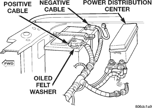
(3) Refer to the label on the PDC for horn relay identification and location.
(4) Remove the horn relay by unplugging it from the PDC.
(5) Install the horn relay by aligning the relay terminals with the cavities in the PDC and pushing the relay firmly into place.
(6) Install the PDC cover. (7) Connect the battery negative cable. (8) Test the relay operation.
HORN SWITCH
WARNING: ON VEHICLES EQUIPPED WITH A DRIV- ER’S AIRBAG, THE HORN SWITCH IS INTEGRAL TO THE AIRBAG MODULE COVER. SERVICE OF THIS COMPONENT SHOULD BE PERFORMED ONLY BY CHRYSLER-TRAINED AND AUTHORIZED DEALER SERVICE TECHNICIANS. FAILURE TO TAKE THE PROPER PRECAUTIONS OR TO FOLLOW THE PROPER PROCEDURES COULD RESULT IN ACCI- DENTAL, INCOMPLETE, OR IMPROPER AIRBAG DEPLOYMENT AND POSSIBLE PERSONAL INJURY. REFER TO GROUP 8M - PASSIVE RESTRAINT SYS- TEMS FOR THE SERVICE PROCEDURES.
HORN
(1) Disconnect and isolate the battery negative cable.
(2) Raise and support the vehicle.
(3) Remove the radiator lower air deflector. refer to Group 7 - Cooling System for the procedures.
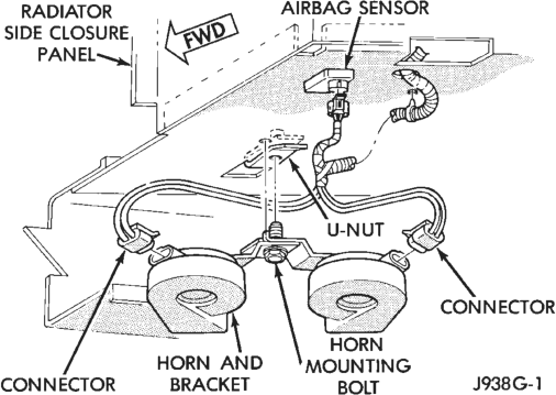
(4) Unplug the horn wiring connectors (Fig. 2). (5) Remove the bolt holding the horn mounting bracket to the radiator closure extension panel and remove the horns.
(6) Reverse the removal procedures to install. Tighten the horn bracket mounting bolt to 30 N·m (22 ft. lbs.).