Heating and Air Conditioning — 1996 Jeep Grand Cherokee ZJ Service Manual
Pages 1439–1483 · 45 pages · 19 words repaired
GENERAL INFORMATION
HEATER AND AIR CONDITIONER
A manual temperature control type heating-air conditioning system is standard factory-installed equipment on this model. An electronically controlled Automatic Temperature Control (ATC) type heatingair conditioning system is an available factory-installed option.
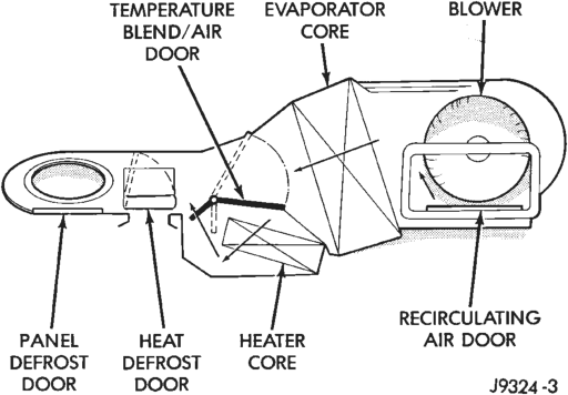
All vehicles are equipped with a common heater- A/C housing assembly (Fig. 1). The system combines air conditioning, heating, and ventilating capabilities in a single unit housing mounted under the instrument panel.
System
Outside fresh air enters the vehicle through the cowl top opening at the base of the windshield, and passes through a plenum chamber to the heater-A/C system blower housing. Air flow velocity can then be adjusted with the blower motor speed selector switch on the heater-A/C control panel. The air intake openings must be kept free of snow, ice, leaves, and other obstructions for the heater-A/C system to receive a sufficient volume of outside air.
The heater-air conditioner is a blend-air type system. In a blend-air system, a blend-air door controls the amount of cooled or unconditioned air is allowed to flow through, or around, the heater core. A temperature control knob on the heater-A/C control panel determines the discharge air temperature by actuating the blend-air door. This allows an almost immediate control of the system’s output air temperature.
The mode control knob on the heater-A/C control panel is used to direct the conditioned air to the selected system outlets. On manual temperature control systems, the mode control knob switches engine vacuum to control the mode doors, which are operated by vacuum actuator motors. On ATC systems, the mode control knob switches electrical current to control the mode doors, which are operated by electronic actuator motors.
The outside air intake can be shut off by selecting the recirculation mode with the mode control knob. This will open the recirculating air door and recirculate the air that is already inside the vehicle.
The air conditioner for all models is designed for the use of non-CFC, R-134a refrigerant. The air conditioning system has an evaporator to cool and dehumidify the incoming fresh or recirculated air prior to blending it with the heated air. This system uses a fixed orifice tube in the condenser outlet line to meter refrigerant flow to the evaporator coil. To maintain minimum evaporator temperature, a fixed pressure setting switch on the accumulator cycles the compressor clutch.
HEATER AND AIR CONDITIONER CONTROLS
The manual temperature control heater-A/C system uses a combination of electrical, and vacuum controls. The ATC heater-A/C system uses only electrical controls. These controls provide the vehicle operator with a number of setting options to help control the climate and comfort within the vehicle. Refer to the Owner’s Manual for more information on the suggested operation and use of these controls.
Both heater-A/C control panels are located to the right of the instrument cluster on the instrument panel (Fig. 2). Both control panels have a temperature control knob, a mode control knob, a blower motor switch knob, and an A/C push-button switch. The ATC control panel includes a Recirc push-button switch and a vacuum fluorescent display area.
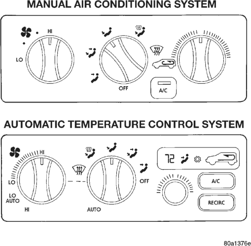
The ATC control panel also includes the ATC controller. The ATC controller contains a microprocessor and uses internal programming along with hardwired sensor inputs and messages received on the CCD data bus network to control the many functions and features of the ATC system.
The manual temperature control panel and/or the ATC control panel/controller units cannot be repaired and, if faulty, must be replaced.
SERVICE WARNINGS AND PRECAUTIONS
WARNING: THE AIR CONDITIONING SYSTEM CON- TAINS REFRIGERANT UNDER HIGH PRESSURE. SEVERE PERSONAL INJURY MAY RESULT FROM IMPROPER SERVICE PROCEDURES. REPAIRS SHOULD ONLY BE PERFORMED BY QUALIFIED SERVICE PERSONNEL.
• AVOID BREATHING THE REFRIGERANT AND REFRIGERANT OIL VAPOR OR MIST. EXPOSURE MAY IRRITATE EYES, NOSE, AND/OR THROAT. WEAR EYE PROTECTION WHEN SERVICING THE AIR CONDITIONING REFRIGERANT SYSTEM. SERI- OUS EYE INJURY CAN RESULT FROM DIRECT CONTACT WITH THE REFRIGERANT. IF EYE CON- TACT IS MADE, SEEK MEDICAL ATTENTION IMME- DIATELY.
• DO NOT EXPOSE THE REFRIGERANT TO OPEN FLAME. POISONOUS GAS IS CREATED WHEN REFRIGERANT IS BURNED. AN ELEC- TRONIC LEAK DETECTOR IS RECOMMENDED.
• IF ACCIDENTAL SYSTEM DISCHARGE OCCURS, VENTILATE THE WORK AREA BEFORE RESUMING SERVICE. LARGE AMOUNTS OF REFRIGERANT RELEASED IN A CLOSED WORK AREA WILL DISPLACE THE OXYGEN AND CAUSE SUFFOCATION.
• THE EVAPORATION RATE OF R-134a REFRIG- ERANT AT AVERAGE TEMPERATURE AND ALTI- TUDE IS EXTREMELY HIGH. AS A RESULT, ANYTHING THAT COMES IN CONTACT WITH THE REFRIGERANT WILL FREEZE. ALWAYS PROTECT THE SKIN OR DELICATE OBJECTS FROM DIRECT CONTACT WITH THE REFRIGERANT.
• THE R-134a SERVICE EQUIPMENT OR THE VEHICLE REFRIGERANT SYSTEM SHOULD NOT BE PRESSURE TESTED OR LEAK TESTED WITH COM- PRESSED AIR. SOME MIXTURES OF AIR AND R-134a HAVE BEEN SHOWN TO BE COMBUSTIBLE AT ELEVATED PRESSURES. THESE MIXTURES ARE POTENTIALLY DANGEROUS, AND MAY RESULT IN FIRE OR EXPLOSION CAUSING INJURY OR PROP- ERTY DAMAGE.
CAUTION: Liquid refrigerant is corrosive to metal surfaces. Follow the operating instructions supplied with equipment being used.
• Never add R-12 to a refrigerant system designed to use R-134a. Damage to the system will result.
• R-12 refrigerant oil must not be mixed with the R-134a refrigerant oil. They are not compatible.
• Do not use R-12 equipment or parts on the R-134a system. Damage to the system will result.
• Do not over-charge the refrigerant system. This will cause excessive compressor head pressure and can cause noise and system failure.
In addition to the warnings and cautions listed above, the following precautions must also be observed whenever servicing the air conditioning system:
• Recover the refrigerant before opening any fitting or connection. Open the fittings with caution even after the system has been discharged. Never open or loosen a connection before recovering the refrigerant.
• The refrigerant system must always be evacuated before charging.
• Do not open the refrigerant system or uncap a replacement component until you are ready to service the system. This will prevent contamination in the system.
• Before disconnecting a component, clean the outside of the fittings thoroughly to prevent contamination from entering the refrigerant system.
• Immediately after disconnecting a component from the refrigerant system, seal the open fittings with a cap or plug.
• Before connecting an open refrigerant fitting, always install a new seal or gasket. Coat the fitting and seal with clean refrigerant oil before connecting.
• Do not remove the sealing caps from a replacement component until ready to install it.
• When installing a refrigerant line, avoid sharp bends. Position the lines away from the exhaust, or any sharp edges which may chafe the line.
• Tighten fittings only to the specified torque. The aluminum fittings used in the refrigerant system will not tolerate over-tightening.
• When disconnecting a fitting, use a wrench on both halves of the fitting. This will prevent twisting of the refrigerant lines or tubes.
• Refrigerant oil will absorb moisture from the atmosphere, if left uncapped. Do not open a container of oil until you are ready to use it. Install the cap immediately after using. Store the oil only in a clean moisture-free container.
• Keep service tools and the work area clean. Contamination of the refrigerant system through careless work habits must be avoided.
COOLING SYSTEM REQUIREMENTS
To maintain the performance level of the heatingair conditioning system, the engine cooling system must be properly maintained.
The use of a bug screen is not recommended. Any obstructions in front of the radiator or condenser will reduce the performance of the air conditioning and engine cooling systems.
COOLANT PRECAUTIONS
WARNING: ANTIFREEZE IS AN ETHYLENE GLY- COL BASED COOLANT AND IS HARMFUL IF SWAL- LOWED OR INHALED. IF SWALLOWED, DRINK TWO GLASSES OF WATER AND INDUCE VOMIT- ING. IF INHALED, MOVE TO A FRESH AIR AREA. SEEK MEDICAL ATTENTION IMMEDIATELY.
• WASH THE SKIN AND CLOTHING THOR- OUGHLY AFTER COMING IN CONTACT WITH ETH- YLENE GLYCOL.
• KEEP OUT OF THE REACH OF CHILDREN AND PETS.
• DO NOT OPEN A COOLING SYSTEM WHEN THE ENGINE IS AT OPERATING TEMPERATURE. PERSONAL INJURY MAY RESULT.
• DO NOT STORE ENGINE COOLANT IN OPEN OR UNMARKED CONTAINERS.
• HOT ENGINE COOLANT CAN CAUSE SEVERE BURNS. DO NOT OPEN THE RADIATOR DRAIN COCK WHEN THE COOLING SYSTEM IS HOT AND PRESSURIZED. ALLOW THE COOLANT TO DECREASE TO ROOM TEMPERATURE BEFORE STARTING REPAIR OPERATIONS.
The engine cooling system is designed to develop internal pressures of 97 to 124 kPa (14 to 18 psi). Allow the vehicle 15 minutes to cool down, or until a safe temperature and pressure are attained, before opening the cooling system. Refer to Group 7 - Cooling System for more information.
REFRIGERANT HOSES/TUBES PRECAUTIONS
Kinks or sharp bends in the refrigerant tubing or hoses will reduce the capacity of the entire system. High pressures are produced in the system when it is operating. Extreme care must be exercised to make sure that all connections are pressure tight.
A good rule for the flexible hose refrigerant lines is to keep the radius of all bends at least ten times the diameter of the hose. Sharp bends will reduce the flow of refrigerant. The flexible hose lines should be routed so they are at least 80 mm (3 inches) from the exhaust manifold. It is a good practice to inspect all flexible hose lines at least once a year to make sure they are in good condition and properly routed.
There are two types of refrigerant fittings:
• All fittings with O-rings need to be coated with refrigerant oil before installation. Use only O-rings approved for use with R-134a refrigerant. Failure to do so may result in a leak.
• Unified plumbing connections with aluminum gaskets cannot be serviced with O-rings. The gaskets are not reusable and new gaskets do not require lubrication before installing.
Using the proper wrenches when making a connection is very important. Improper wrenches or improper use of the wrenches can damage the fittings. Always use two wrenches when loosening or tightening tube fittings. Use one wrench to hold the stationary part while loosening or tightening with the other wrench.
The refrigerant must be recovered completely before opening any fitting or connection. Open the fittings with caution, even after the refrigerant has been recovered. If any pressure is noticed as a fitting is loosened, tighten the fitting and recover the system again.
Do not discharge refrigerant into the atmosphere. Use an R-134a refrigerant recovery/recycling device that meets SAE Standard J2210.
The refrigerant system will remain chemically stable as long as pure, moisture-free R-134a refrigerant oil is used. Dirt, moisture, or air can upset this chemical stability. Operational troubles or serious damage can occur if foreign material is present in the refrigerant system.
When it is necessary to open the refrigerant system, have everything needed to service the system ready. The system should not be left open any longer than necessary. Cap or plug all lines and fittings as soon as they are opened to prevent the entrance of dirt and moisture. All lines and components in parts stock should be capped or sealed until they are ready to be used.
All tools, including the refrigerant recycling equipment, the manifold gauge set, and test hoses should be kept clean and dry. All tools and equipment must be designed for R-134a refrigerant.
DESCRIPTION AND OPERATION
ACCUMULATOR
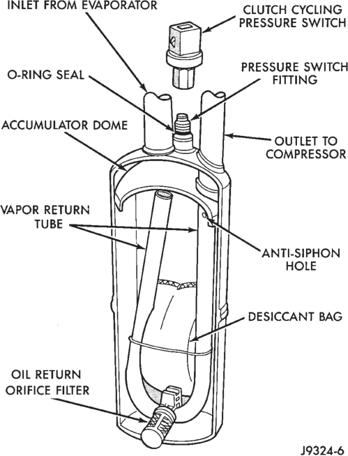
The accumulator is mounted in the engine compartment between the evaporator coil outlet tube and the compressor inlet. Refrigerant enters the accumulator canister as a low pressure vapor through the inlet tube. Any liquid, oil-laden refrigerant falls to the bottom of the canister, which acts as a separator. A desiccant bag is mounted inside the accumulator canister to absorb any moisture which may be in the refrigerant system (Fig. 3).
AMBIENT TEMPERATURE SENSOR
Models with the optional automatic temperature control system use an input from the ambient temperature sensor. The sensor is located in front of the condenser and behind the grille on the center radiator support.
The ambient temperature sensor is hard-wired to the Body Control Module (BCM). The BCM places an ambient temperature message on the CCD data bus for use by the overhead console for the thermometer function, and for use by the ATC controller.
The ambient temperature sensor is a Negative Temperature Coefficient (NTC) thermistor or temperature sensitive resistor. The ATC controller uses this sensor input to monitor the outside air temperature. However, because heat from the radiator and condenser can affect the accuracy of this sensor input when the vehicle is not moving, this input is only used by the ATC system when the vehicle is in motion.
The ambient temperature sensor cannot be adjusted or repaired and, if faulty or damaged, it must be replaced.
BLOWER MOTOR
The blower motor and blower wheel are located in the right end of the heater-A/C housing, below the glove box. It can be removed from the passenger compartment side of the housing. The blower motor circuit is protected by a fuse in the junction block.
The blower motor will only operate when the ignition switch is in the On position, and the heater-A/C mode control switch is in any position, except Off. On models with the standard manual temperature control system, the blower motor speed is controlled by the blower motor switch and resistor. On models with the optional ATC system, the blower motor speed is controlled by the blower motor switch and the power module.
The blower motor cannot be repaired and, if faulty, must be replaced.
BLOWER MOTOR POWER MODULE
Models equipped with the optional ATC system have a blower motor power module. The power module allows infinitely variable blower motor speeds. The power module is mounted on the heater-A/C blower housing in the same location used for the blower motor resistor on manual temperature control systems.
The power module output to the blower motor can be controlled manually by using the blower motor switch knob on the heater-A/C control panel, or automatically by the circuitry of the ATC controller. In either case, the ATC controller sends the correct pulse width modulated signal to the power module to provide the proper blower motor speed.
The power module cannot be repaired and, if faulty, it must be replaced.
BLOWER MOTOR RESISTOR
Models with the standard manual temperature control system have a blower motor resistor. The blower motor resistor contains several resistor wires. The blower motor receives ignition switched battery feed from a fuse in the junction block. The blower motor speed is controlled by changing the resistance in the blower motor ground path through the blower motor switch and the blower motor resistor wires.
With the blower motor switch in the lowest speed position, the ground path for the motor is applied through all of the resistor wires. Each higher speed selected with the blower motor switch applies the blower motor ground path through fewer of the resistor wires, increasing the blower motor speed. When the blower motor switch is in the highest speed position, the blower motor resistor is bypassed and the ground circuit is applied directly to the blower motor.
The blower motor resistor cannot be repaired and, if faulty, must be replaced.
BLOWER MOTOR SWITCH
The heater-A/C blower motor is controlled by a rotary switch, mounted in the heater-A/C control panel. On vehicles with manual temperature control systems, the switch allows the selection of four blower motor speeds, but will only operate with the ignition switch in the On position, and the heater- A/C mode control switch in any position except Off. On vehicles with ATC systems, the switch allows the selection of Lo Auto, Hi Auto, and an infinite number of manual speed settings between Lo and Hi.
On manual temperature control systems, the blower motor switch is connected in series with the blower motor ground circuit through the heater-A/C mode control switch. The blower motor switch directs this ground path to the blower motor through the blower motor resistor wires, or directly to the blower motor, as required to achieve the selected blower motor speed.
On ATC systems, the blower motor switch is just one of many inputs to the ATC controller. In the manual blower modes, the ATC controller adjusts the blower motor speed through the power module or the high speed blower motor relay as required by the blower switch position. In the auto blower modes, the ATC controller it is selected with the blower adjusts the blower motor speed through the power module or the high speed blower motor relay as required to achieve and maintain the selected comfort level.
The blower motor switch cannot be repaired and, if faulty, must be replaced. The switch is serviced only as a part of the heater-A/C control assembly.
COMPRESSOR
The air conditioning system uses a Nippon Denso 10PA17 fixed displacement compressor on all models. A label identifying the use of R-134a refrigerant is located on the compressor. The purpose of the compressor is to compress the low-pressure refrigerant vapor from the evaporator into a high-pressure, hightemperature vapor. The compressor is serviced only as an assembly.
COMPRESSOR CLUTCH
The compressor clutch assembly consists of a stationary electromagnetic coil, a hub bearing and pulley assembly, and a clutch plate (Fig. 4). The electromagnetic coil and pulley are retained on the compressor with snap rings. The clutch plate is mounted on the compressor shaft and secured with a bolt.
These components provide the means to engage and disengage the compressor from the engine serpentine accessory drive belt. When the clutch coil is energized, it magnetically draws the clutch into contact with the pulley and drives the compressor shaft.
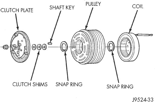
When the coil is not energized, the pulley free-wheels on the clutch hub bearing, which is part of the pulley. The compressor clutch and coil are the only serviced parts on the compressor.
The compressor clutch is controlled by several components: the A/C switch on the heater-A/C control panel, the ATC controller, the low pressure cycling clutch switch, the high pressure cut-off switch, the compressor clutch relay, and the Powertrain Control Module (PCM). The PCM may delay compressor clutch engagement for up to 30 seconds. Refer to Group 14 - Fuel System for more information on the PCM controls.
COMPRESSOR CLUTCH RELAY
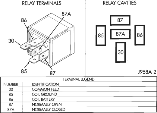
The compressor clutch relay is a International Standards Organization (ISO) micro-relay. The terminal designations and functions are the same as a conventional ISO relay. However, the micro-relay terminal orientation (footprint) is different, current capacity is lower, and the relay case dimensions are smaller than on the conventional ISO relay.
The compressor clutch relay is a electro-mechanical device that switches current to the compressor clutch coil when the Powertrain Control Module (PCM) grounds the coil side of the relay. The PCM responds to inputs from the A/C switch on the heater-A/C control panel, the ATC controller, the low pressure cycling clutch switch, and the high pressure cut-off switches.
The compressor clutch relay is located in the Power Distribution Center (PDC) in the engine compartment. Refer to the PDC label for relay identification and location.
CONDENSER
The condenser is located in front of the engine cooling radiator. It is a heat exchanger that allows the high-pressure refrigerant gas to give up its heat to the air passing over the condenser fins. This causes the refrigerant gas to condense into a high-pressure liquid refrigerant. The condenser is serviced only as an assembly.
EVAPORATOR COIL
The evaporator coil is located in the A/C housing, under the instrument panel. Refrigerant enters the evaporator as a low-temperature, low-pressure liquid. As air passes over the fins of the evaporator, the humidity in the air condenses on the fins, and the heat from the air is absorbed by the refrigerant. Heat absorption causes the refrigerant to become a lowpressure gas before it leaves the evaporator.
The evaporator coil cannot be repaired and, if faulty, it must be replaced.
FIXED ORIFICE TUBE
The fixed orifice tube is integral to the liquid line located between outlet tube of the condenser and the inlet tube of the evaporator. The inlet and outlet ends of the tube have a screen to filter the refrigerant. O-rings on the tube body prevent the refrigerant from by-passing the fixed orifice. The fixed orifice tube is used to meter the flow of liquid refrigerant into the evaporator coil. The fixed orifice tube cannot be repaired and, if faulty or plugged, the liquid line must be replaced.
HIGH PRESSURE CUT-OFF SWITCH
The high pressure cut-off switch is located on the discharge line near the compressor. When the discharge line pressure rises above 3100-3375 kPa (450- 490 psi) the switch interrupts power to the compressor clutch. This switch prevents compressor operation when the discharge line pressure approaches high levels. The switch will cut-in when the pressure drops to 1860-2275 kPa (270-330 psi). The switch is a factory-calibrated unit. The high pressure cut-off switch cannot be adjusted or repaired and, if faulty, must be replaced.
HIGH PRESSURE RELIEF VALVE
The high pressure relief valve is located on the compressor manifold. The valve is used to prevent excessive system pressure. The valve vents the system when a pressure of 3445 to 4135 kPa (500 to 600 psi), and above, is reached. This prevents damage to the compressor and other system components due to condenser air flow being restricted or an over-charge of refrigerant. The valve closes with a minimum pressure of 2756 kPa (400 psi).
The high pressure relief valve vents only enough refrigerant to reduce system pressure, and then re-seats itself. The majority of the refrigerant is conserved in the system. If the valve vents refrigerant, it does not mean the valve is faulty. The valve is part of the compressor assembly and must not be removed or otherwise disturbed.
HIGH SPEED BLOWER MOTOR RELAY
Models equipped with the optional ATC system have a high speed blower motor relay. The relay is a International Standards Organization (ISO)-type relay. The high speed blower motor relay is a electromechanical device that switches current to the blower motor, bypassing the blower motor power module, when the relay coil is provided a ground signal by the ATC controller. See the Diagnosis and Testing section of this group for more information on the relay’s operation.
The high speed blower motor relay is located on the right end of the heater-A/C housing, near the blower motor. The relay cannot be repaired and, if faulty, it must be replaced.
IN-VEHICLE TEMPERATURE SENSOR
Models equipped with an ATC system have an invehicle temperature sensor. The in-vehicle temperature sensor is located behind the lower right instrument panel module, just inboard of the glove box and below the right center panel outlet.
The in-vehicle temperature sensor is a Negative Temperature Coefficient (NTC) thermistor or temperature sensitive resistor. Air passing over a venturi in the heater-A/C housing creates a vacuum, which draws air from inside the vehicle past the sensor through an aspirator hose and tube. The sensor provides a signal to the ATC controller that represents the temperature of the air inside the vehicle.
The ATC controller uses the in-vehicle temperature sensor signal input to adjust the blower speed, blendair door position, and mode door selection in order to maintain the selected comfort level. The sensor cannot be adjusted or repaired and, if faulty, it must be replaced.
LOW PRESSURE CYCLING CLUTCH SWITCH
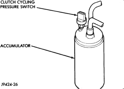
The low pressure cycling clutch switch is mounted on top of the accumulator. The switch is connected in series with the high pressure cut-off switch, between ground and the A/C pressure switch sense circuit cavity of the Powertrain Control Module (PCM). The switch contacts open and close causing the PCM to turn the compressor clutch on and off. This regulates the system pressure and controls evaporator temperature. Controlling evaporator temperature prevents condensate water on the evaporator fins from freezing and obstructing air conditioning system air flow.
The switch contacts are normally open when the suction pressure is approximately 172 kPa (25 psi) or lower. The switch will close when the suction pressure rises to approximately 296 kPa (43 psi) or above. Lower ambient temperatures, below approximately -1°C (30°F) during cold weather will also open the switch contacts. This is due to the pressure/temperature relationship of the refrigerant in the system.
The low pressure cycling clutch switch is a factorycalibrated unit. It cannot be adjusted or otherwise repaired. If faulty, the switch must be replaced.
REFRIGERANT
The R-134a refrigerant used in this air conditioning system is a non-toxic, non-flammable, clear, and colorless liquefied gas. R-134a refrigerant is not compatible with R-12 refrigerant in an air conditioning system. Even a small amount of R-12, added to a R-134a refrigerant system, will cause compressor failure, refrigerant oil sludge, or poor air conditioning system performance.
The refrigerant system service ports have been designed to ensure that the system is not accidentally filled with the wrong refrigerant (R-12).
REFRIGERANT LINE COUPLERS
Spring locking couplers are used to connect refrigerant lines and other components to the refrigerant system. The coupling is held together by a garter spring inside a circular cage.
When the coupling halves are connected, the flared end of the female fitting slips behind the garter spring inside the cage of the male fitting. The garter spring and cage prevent the flared end of the female fitting from pulling out of the cage. Secondary clips are installed over the coupling at the factory for added blow-off protection.
O-rings are used to seal the coupling. These O-rings are compatible with R-134a refrigerant and must be replaced with O-rings made of the same material.
REFRIGERANT LINES
The refrigerant lines are used to carry the refrigerant between the various air conditioning system components. A barrier hose design is used for the air conditioning system on this vehicle. The ends of the refrigerant hoses are made from lightweight aluminum, and use braze-less fittings. The refrigerant lines and hoses cannot be repaired and, if faulty, must be replaced.
REFRIGERANT OIL
The oil used in the 10PA17 compressor is a polyalkylene glycol, synthetic (ND8 PAG), wax-free refrigerant oil. Use only refrigerant oil of the same type to service the system. Refrigerant oil will absorb any moisture it comes in contact with, even moisture in the air. The oil container should be kept tightly capped until it is ready to be used. Then, cap the oil immediately after using, to prevent contamination.
REFRIGERANT SYSTEM SERVICE EQUIPMENT
WARNING: EYE PROTECTION MUST BE WORN WHEN SERVICING AN AIR CONDITIONING REFRIG- ERANT SYSTEM. TURN OFF (ROTATE CLOCKWISE) ALL VALVES ON THE EQUIPMENT BEING USED, BEFORE PROCEEDING WITH THIS OPERATION. FAILURE TO OBSERVE THESE WARNINGS MAY RESULT IN PERSONAL INJURY.
When servicing the air conditioning system, a refrigerant charging station and a recovery/recycling device for R-134a must be used. This device must meet SAE Standard J2210. Contact an automotive service equipment supplier for refrigerant charging and recycling/recovering equipment. Refer to the operating instructions provided with the equipment for proper operation.
A manifold gauge set may be needed with some charging and/or recovery/recycling devices (Fig. 5). The service hoses on the gauge set being used should have manual (turn wheel), or automatic, back-flow valves at the service port connector ends. This will prevent refrigerant from being released into the atmosphere.
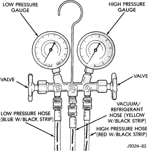
MANIFOLD GAUGE SET CONNECTIONS
CAUTION: Do not use an R-12 manifold gauge set on an R-134a system. The refrigerants are not compatible and system damage will result.
LOW PRESSURE GAUGE HOSE
The low pressure hose (Blue with Black stripe) attaches to the suction service port. This port is located at the right front of the engine compartment in the suction line.
HIGH PRESSURE GAUGE HOSE
The high pressure hose (Red with Black stripe) attaches to the discharge service port. This port is located on the discharge line between the compressor and the condenser.
RECOVERY/RECYCLING/EVACUATION/CHARGING HOSE
The center manifold hose (Yellow, or White, with Black stripe) is used to recover, evacuate, and charge the refrigerant system. When the low or high pressure valves on the manifold gauge set are opened, the refrigerant in the system will escape through this hose.
REFRIGERANT SYSTEM SERVICE PORTS
The service ports are used to charge, recover/recycle, evacuate, and test the air conditioning refrigerant system. Unique service port coupler sizes are used on the R-134a system, to ensure that the system is not accidentally contaminated by the use of the wrong refrigerant (R-12), or refrigerant service equipment.
The high pressure service port is located on the compressor manifold or plumbing. The low pressure service port is located on the suction line. After servicing the refrigerant system, always re-install the service port caps.
SOLAR SENSOR
Models equipped with the optional ATC system have a solar sensor. The solar sensor is mounted in the cowl top trim panel, on the top of the instrument panel near the right defroster outlet. The sensor is a photo diode which responds to sunlight intensity, not to temperature.
The ATC controller uses the solar sensor input to calculate and compensate for the potential effects of heat gain in bright sunlight and heat loss with an overcast sky, or at night. It then adjusts the blower speed, blend air door position, and mode door position as needed to maintain the selected comfort level.
The solar sensor cannot be adjusted or repaired and, if faulty or damaged, it must be replaced.
DIAGNOSIS AND TESTING
A/C PERFORMANCE
The air conditioning system is designed to provide the passenger compartment with low temperature and low humidity air. The evaporator, located in the heater-A/C housing behind the instrument panel, is cooled to temperatures near the freezing point. As warm damp air passes over the fins in the evaporator, the air is cooled and the moisture is removed as it condenses on the fins. During periods of high heat and humidity, an air conditioning system will be more effective in the Recirc mode. With the system in the Recirc mode, only air from the passenger compartment passes through the evaporator. As the passenger compartment air dehumidifies, the air conditioning system performance levels improve.
Humidity has an important bearing on the temperature of the air delivered to the vehicle’s interior. It is important to understand the effect that humidity has on the performance of the air conditioning system. When humidity is high, the evaporator has to perform a double duty. It must lower the air temperature, and it must lower the temperature of the moisture in the air that condenses on the evaporator’s fins. Condensing the moisture in the air transfers heat energy into the evaporator fins and tubing. This reduces the amount of heat the evaporator can absorb from the air. High humidity greatly reduces the evaporator’s ability to lower the temperature of the air.
However, evaporator capacity used to reduce the amount of moisture in the air is not wasted. Wringing some of the moisture out of the air entering the vehicle adds to the comfort of the passengers. Although, an owner may expect too much from their air conditioning system on humid days. A performance test is the best way to determine whether the system is performing up to standard. This test also provides valuable clues as to the possible cause of trouble with the air conditioning system.
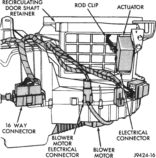
If the vehicle has the ATC system, and has intermittent operational problems or fault codes, be certain that the 16-way electrical connector on the heater-A/C housing is properly seated (Fig. 6). To check this condition, unplug the two connector halves and then reconnect them. Historical fault codes that could be stored as a result of this unseated connector condition are Codes 36, 38, and 39.
Review the Service Warnings and Precautions in the front of this group before performing this procedure. The air temperature in the test room and in the vehicle must be a minimum of 21°C (70°F) for this test.
(1) Connect a tachometer and a manifold gauge set.
(2) Set the heater-A/C controls in the A/C, Panel, and Recirc positions, the temperature control knob in the full cool position, and the blower motor switch in the full Hi position.
(3) Start the engine and hold the idle at 1,000 rpm with the compressor clutch engaged.
(4) The engine should be at operating temperature. The doors and windows must be open.
(5) Insert a thermometer in the left center A/C (panel) outlet. Operate the engine for five minutes.
(6) The compressor clutch may cycle, depending upon the ambient temperature and humidity. If the clutch cycles, remove the low pressure cycling clutch switch connector from the switch located on the accumulator (Fig. 7). Place a jumper wire across the terminals of the low pressure cycling clutch switch connector.
(7) With the compressor clutch engaged, record the discharge air temperature and the compressor discharge pressure.
(8) Compare the discharge air temperature to the Performance Temperature and Pressure chart. If the discharge air temperature is high, see Refrigerant System Leaks and Refrigerant System Charge in this group.
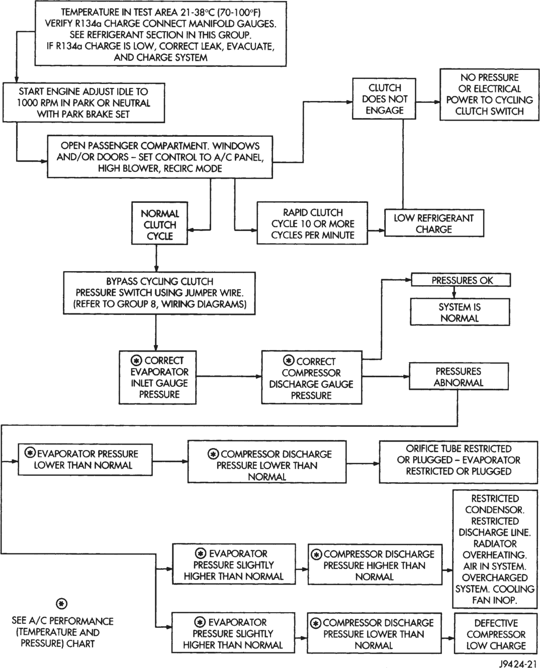
(9) Compare the compressor discharge pressure to the Performance Temperature and Pressure chart. If the compressor discharge pressure is high, see the Pressure Diagnosis chart.
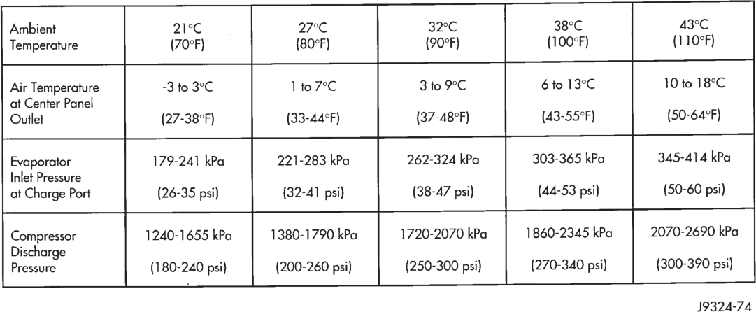
Performance Temperature and Pressure Chart
Pressure Diagnosis
HEATER PERFORMANCE
PREPARATIONS
Review the Service Warnings and Precautions in the front of this group before performing the following procedures.
Check the radiator coolant level, serpentine drive belt tension, and engine vacuum line connections. Also check the radiator air flow and the radiator fan operation. Start the engine and allow it to warm up to normal operating temperature.
WARNING: DO NOT REMOVE THE RADIATOR CAP WHEN THE ENGINE IS AT OPERATING TEMPERA- TURE, PERSONAL INJURY MAY RESULT.
If the vehicle has been operated recently, wait 15 minutes or longer before removing the radiator cap. Place a rag over the cap and turn it to the first safety stop. Allow any pressure to escape through the overflow tube. When the system stabilizes, remove the cap completely.
MAXIMUM HEATER OUTPUT
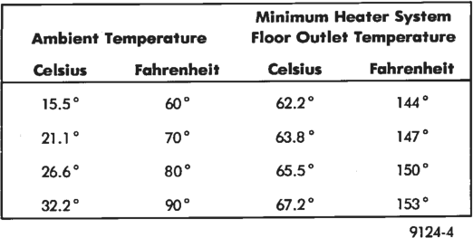
Engine coolant is delivered to the heater core through two heater hoses. With the engine idling at normal operating temperature, set the temperature control knob in the full heat position, the mode control knob in the Floor position, and the blower motor switch knob in the full Hi position. Using a test thermometer, check the air temperature coming from the floor outlets, refer to the Temperature Reference Chart.
Temperature Reference Chart
If the floor outlet air temperature is low, refer to Group 7 - Cooling System for the coolant temperature specifications. Both of the heater hoses should be hot to the touch. The coolant return hose should be slightly cooler than the supply hose. If the coolant return hose is much cooler than the supply hose, locate and repair the engine coolant flow obstruction in the heater system.
OBSTRUCTED COOLANT FLOW
Possible locations or causes of obstructed coolant flow:
• Pinched or kinked heater hoses. • Improper heater hose routing. • Plugged heater hoses or supply and return ports at the cooling system connections (refer to Group 7 - Cooling System).
• A plugged heater core. If proper coolant flow through the heater system is verified, and outlet air temperature is still low, a mechanical problem may exist.
MECHANICAL PROBLEMS
Possible locations or causes of insufficient heat: • An obstructed cowl air intake. • Obstructed heater system outlets. • A blend-air door not functioning properly.
TEMPERATURE CONTROL
If the heater discharge air temperature cannot be adjusted with the temperature control knob on the heater-A/C control panel, the following could require service:
• The heater-A/C control panel. • The blend air door actuator. • The wiring circuits for the heater-A/C control panel or the blend air door actuator.
• Improper engine coolant temperature.
VACUUM SYSTEM
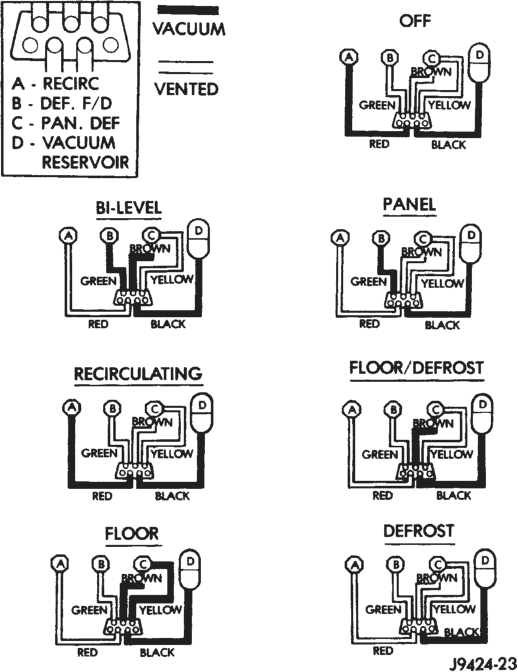
Vacuum control is used to operate the mode doors in the manual temperature control system heater- A/C housing. Testing of the heater-A/C mode control switch operation will determine if the vacuum, and mechanical controls are functioning. However, it is possible that a vacuum control system that operates perfectly at engine idle (high engine vacuum) may not function properly at high engine speeds or loads (low engine vacuum). This can be caused by leaks in the vacuum system, or a faulty vacuum check valve.
A vacuum system test will help to identify the source of poor vacuum system performance, or vacuum system leaks. Before starting this test, stop the engine and make certain that the problem isn’t a disconnected vacuum source tube at the engine intake manifold or the vacuum reservoir.
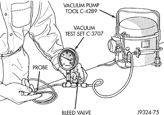
Use an adjustable vacuum test set (Special Tool C-3707) and a suitable vacuum pump to test the heater-A/C vacuum control system. With a finger placed over the end of the vacuum test hose probe (Fig. 8), adjust the bleed valve on the test set gauge to obtain a vacuum of exactly 27 kPa (8 in. Hg.). Release and block the end of the probe several times to verify that the vacuum reading returns to the exact 27 kPa (8 in. Hg.) setting. Otherwise, a false reading will be obtained during testing.
ONE-WAY CHECK VALVE
(1) Disconnect the heater-A/C vacuum supply (black) tube in the engine compartment. This tube passes through an opening in the dash panel.
(2) Remove the one-way vacuum check valve. The valve is located on the (black) vacuum supply hose at the intake manifold.
(3) Connect the test set vacuum supply hose to the heater side of the valve. When connected to this side of the check valve, no vacuum should pass and the test set gauge should return to the 27 kPa (8 in. Hg.) setting. If OK, go to step Step 4. If not OK, replace the faulty valve.
(4) Connect the test set vacuum supply hose to the engine vacuum side of the valve. When connected to this side of the check valve, vacuum should flow through the valve without restriction. If not OK, replace the faulty valve.
HEATER-A/C CONTROLS
(1) Connect the test set vacuum probe to the heater-A/C vacuum supply (black) hose in the engine compartment. Position the test set gauge so that it can be viewed from the passenger compartment.
(2) Place the heater-A/C mode control selector in each mode, one at a time, and pause after each selection. The test set gauge should return to the 27 kPa (8 in. Hg.) setting shortly after each selection is made. If not OK, a component or vacuum line in the selected mode’s circuit has a vacuum leak. See the procedure in Locating Vacuum Leaks.
CAUTION: Do not use lubricant on the switch ports or in the holes in the plug, as lubricant will ruin the vacuum valve in the switch. A drop of clean water in the connector plug holes will help the connector slide onto the switch ports.
LOCATING VACUUM LEAKS
(1) Disconnect the vacuum connector from the back of the heater-A/C mode control switch on the control panel.
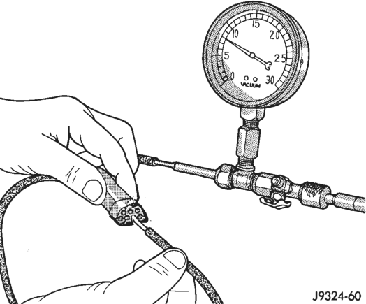
(2) Connect the test set vacuum hose probe to each port in the vacuum harness connector, one at a time, and pause after each connection (Fig. 9). The test set gauge should return to the 27 kPa (8 in. Hg.) setting shortly after each connection is made. If OK, replace the faulty mode control switch. If not OK, go to step Step 3.
(3) Determine the vacuum line color of the vacuum circuit that is leaking. To determine the vacuum line colors, refer to the Vacuum Circuits chart (Fig. 10).
(4) Disconnect and plug the vacuum line from the component (fitting, actuator, valve, switch, or reservoir) on the other end of the leaking circuit. Instrument panel disassembly or removal may be necessary to gain access to some components.
(5) Connect the test set hose or probe to the open end of the leaking circuit. The test set gauge should return to the 27 kPa (8 in. Hg.) setting shortly after each connection is made. If OK, replace the faulty disconnected component. If not OK, go to Step 6.
(6) To locate a leak in a vacuum line, leave one end of the line plugged and connect the test set hose or probe to the other end. Run your fingers slowly along the line while watching the test set gauge. The vacuum reading will fluctuate when your fingers contact the source of the leak. To repair the vacuum line, cut out the leaking section of the line. Then, insert the loose ends of the line into a suitable length of 3mm (1/8-inch) inside diameter rubber hose.
ATC SYSTEM
The ATC controller has a system self-diagnostic mode. The controller is capable of troubleshooting each of its input and output circuits. When the controller detects a fault and places it in memory, an “Er” is momentarily displayed in the heater-A/C control panel vacuum fluorescent display area, but it will only be displayed once during each ignition cycle. The ATC controller is capable of three different types of self-diagnostic tests, as follows:
• Fault Code Tests • Input Circuit Tests • Output Circuit/Actuator Tests The information that follows describes how to read the self-diagnostic display, how to enter the ATC controller self-diagnostic test mode, how to select the three self-diagnostic test types, and how to perform the three different tests.
SELF-DIAGNOSTIC DISPLAY
In the self-diagnostic mode, the test information is displayed in the vacuum fluorescent display area of the heater-A/C control. The area of the display where the temperature control comfort level is normally displayed is called the Test Selector. The Test Selector is used to display fault codes, identify the test mode, and show the values of the circuits being tested. The following information describes how the values in the Test Selector display should be interpreted.
(1) The Select Test mode will have only 00 displayed in the Test Selector, and no stickman will be displayed. This is the self-diagnostic mode from which the various tests may be selected.
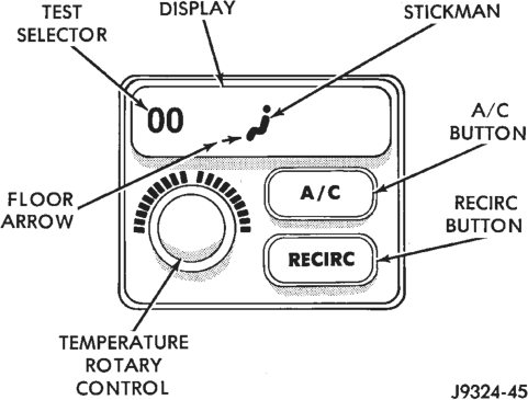
(2) If the stickman floor arrow (bottom) is showing, the displayed Test Selector value will be a range of numbers below 0 (Fig. 11).
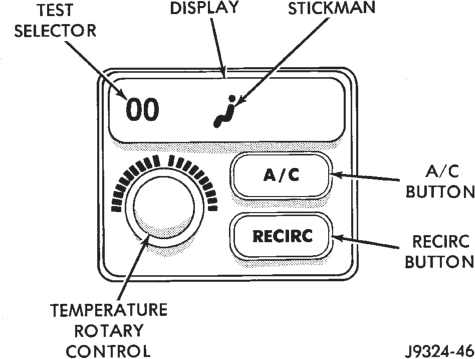
(3) If the stickman appears, but no arrows are showing, the displayed Test Selector value will be a range of numbers between 0 and 99 (Fig. 12).
(4) If the stickman panel arrow (middle) is showing, the displayed Test Selector value will be a range of numbers between 100 and 199 (Fig. 13).
(5) If the stickman panel (middle) and defrost (top) arrows are showing, the displayed Test Selector value will be a range of numbers between 200 and 255 (Fig. 14).
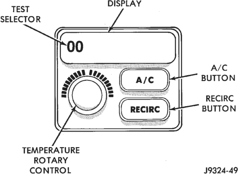
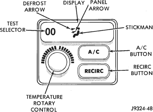
(6) At any time during the self-diagnostic tests, you may return to the Select Test mode by turning the temperature rotary control one click in either direction. Again, the stickman and arrows are not shown in the Select Test mode. At this point, you have the option of monitoring or testing another circuit (Fig. 15).
ENTERING THE ATC SELF-DIAGNOSTIC MODE
To enter the ATC self-diagnostic mode, perform the following:
(1) Depress the A/C and Recirc buttons simultaneously and hold. Rotate the temperature rotary control knob clockwise one click.
(2) If you continue to hold the A/C and Recirc buttons depressed, you will see all of the display segments illuminate. If a segment fails to illuminate, the vacuum fluorescent display is faulty.
(3) After viewing the segment test, release the A/C and Recirc buttons. This will put the Test Selector value at 00, and no stickman will be displayed. This is the Select Test mode. At this point a number of
tests can be selected, however, the Fault Code Test should be performed first.
FAULT CODE TESTS
Fault codes are two-digit numbers that identify a circuit that is malfunctioning. There are two different kinds of fault codes.
1. Current Fault Codes - Current means the fault is present right now. There are two types of current faults: input faults, and system faults.
2. Historical Fault Codes - Historical or stored means the fault occurred previously, but is OK right now. A majority of historical fault codes are caused by intermittent wiring or connector problems.
NOTE: A battery disconnect will erase all faults stored in Read Available Memory (RAM). It is recommended that all faults be recorded before they are erased.
RETRIEVING FAULT CODES
(1) To begin the Fault Code Tests you must be in the Select Test mode. With 00 displayed in the Test Selector and no stickman, push either the A/C or Recirc button.
(2) The stickman will appear indicating you have entered the Fault Code Tests. The values displayed in the Test Selector will range from 00 to 64.
(3) Fault codes will appear and repeat if there are more than one. Record all of the fault codes, then see the Current and Historical Fault Code Charts for the descriptions. If there are no fault codes, the display value remains at 00.
(4) If a Fault Code 25 or 29 is displayed, the ATC Control Module must be replaced before any further testing is performed.
(5) For more detailed information about a fault code, see the Input Circuit Tests or the Output Circuit/Actuator Tests.
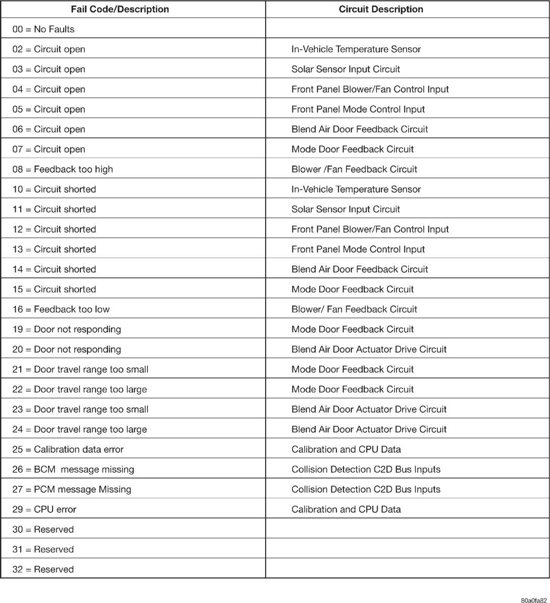
Current Fault Codes
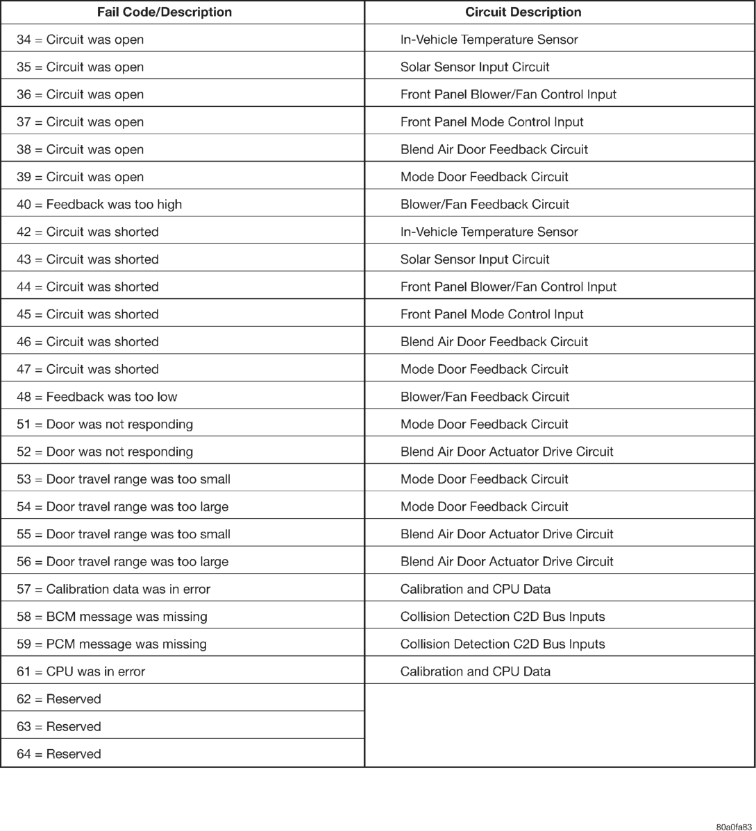
Historical Fault Codes
CLEARING FAULT CODES
Current faults are cleared whenever the problem goes away. To clear a historical fault, depress and hold either the A/C or Recirc button for at least three seconds. The faults have been cleared when two horizontal bars appear in the display.
INPUT CIRCUIT TESTS
In the Input Circuit Test mode, the status of input circuits can be viewed and monitored. If a failure occurs within an input circuit the controller will display a “?” for unknown values, “OC” for an open circuit, or “SC” for a short circuit.
(1) To begin the Input Circuit Tests you must be in the Select Test mode.
(2) With 00 displayed in the Test Selector and no stickman, turn the temperature rotary control until the test number you are looking for appears in the Test Selector display. See the Circuit Testing chart for a listing of the test numbers, test items, test types, system tested, and displayed values.
(3) To see the circuit input values, depress the A/C or Recirc button. The values displayed will represent the input seen by the ATC controller.
OUTPUT CIRCUIT/ACTUATOR TESTS
In the Output Circuit/Actuator Test mode, the output circuits can be viewed, monitored, overridden, and tested. If a failure occurs in an output circuit, test the circuit by overriding the system. Test the actuator through its full range of operation. When the override control has been activated, the display will be flashing. The Test Selector will display feedback information about the output circuit being tested.
(1) To begin the Output Circuit/Actuator Tests you must be in the Select Test mode.
(2) With 00 displayed in the Test Selector and no stickman, turn the temperature rotary control until the test number you are looking for appears in the Test Selector display. See the Circuit Testing chart for a listing of the test numbers, test items, test types, system tested, and displayed values.
(3) To see the output value, depress the A/C or Recirc button. The values displayed will represent the output from the ATC controller.
(4) To enter the actuator test, depress the A/C or Recirc button. The display will blink, indicating you are in the actuator test mode. Manual tests are those in which you will have to depress and hold the A/C or Recirc button to control the output. Automatic tests are those in which you will have to depress the A/C or Recirc button once to generate the output.
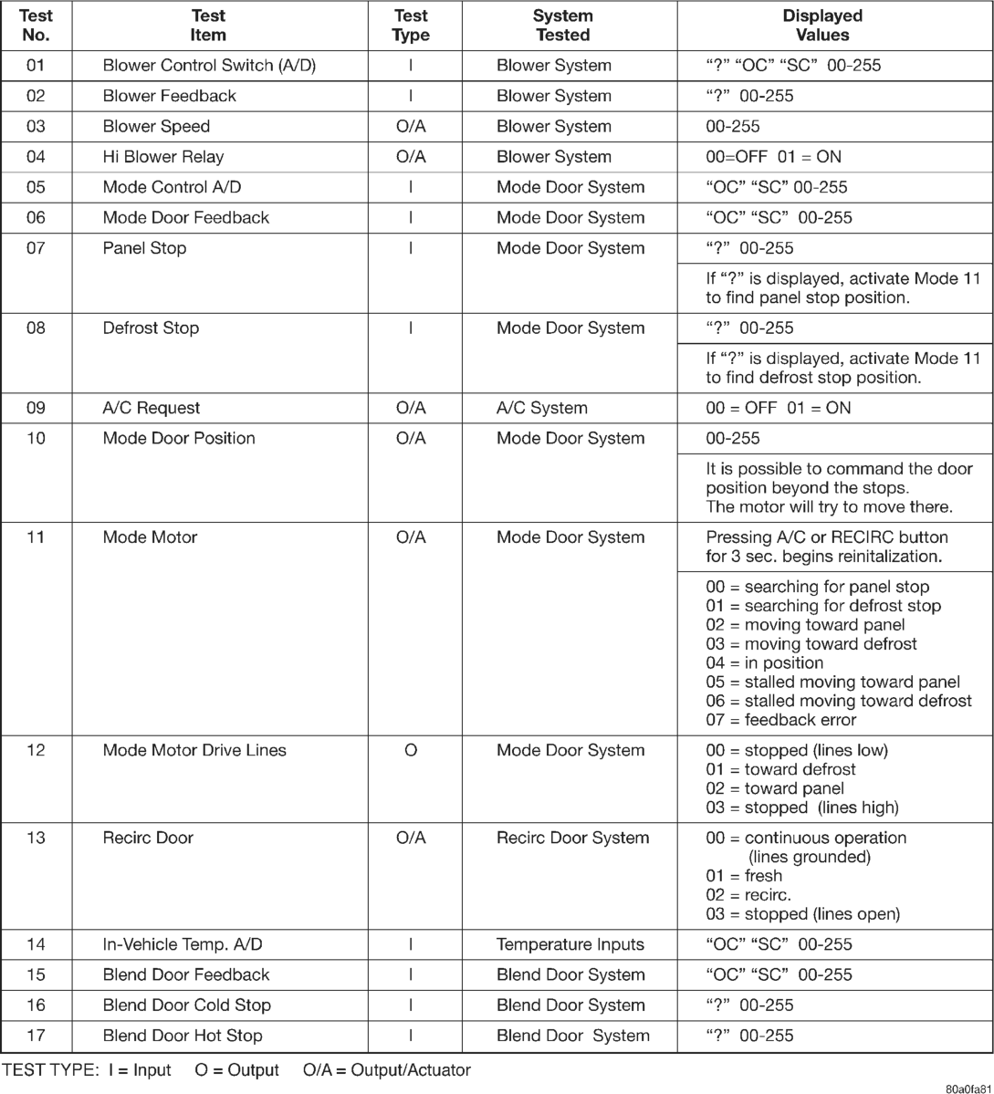
Circuit Testing
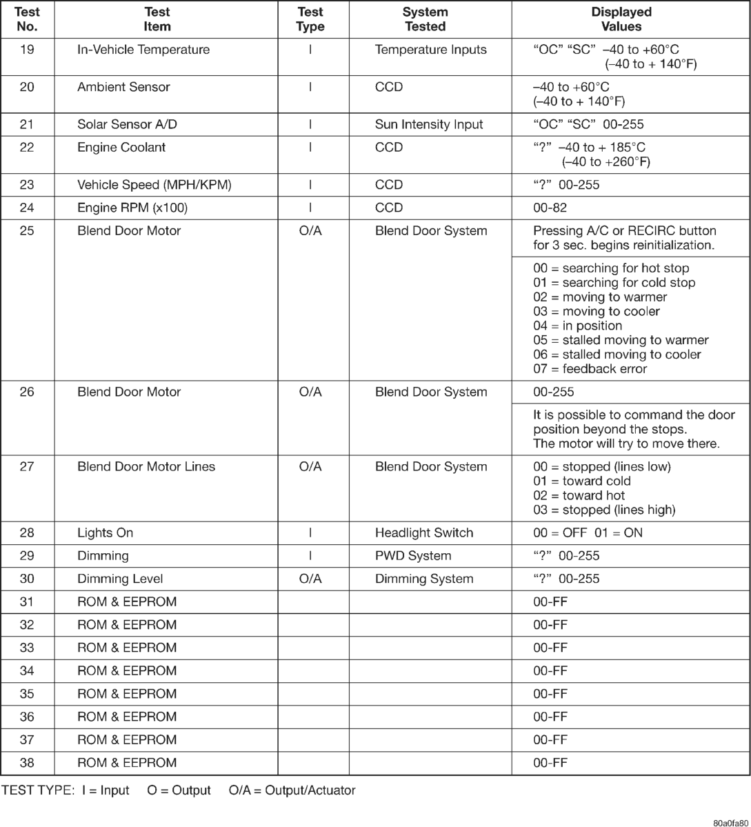
Circuit Testing (cont.)
Blend Air Door Actuator Drive Circuit
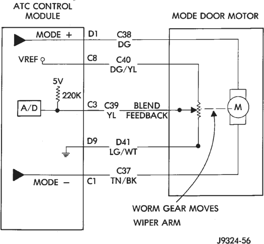
Mode Door Actuator Drive Circuit
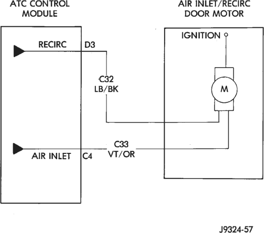
Air Inlet/Recirc Door Actuator Drive Circuit
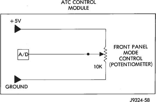
Front Panel Mode Control Circuit
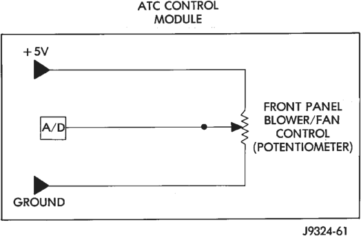
Front Panel Blower/Fan Control Circuit
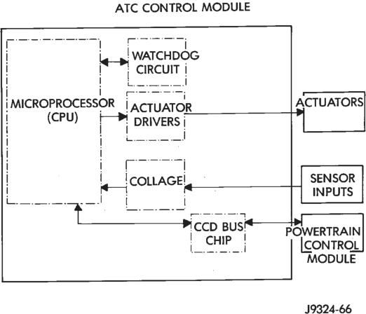
Solar Sensor Circuit
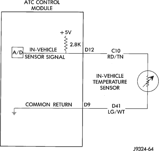
In-Vehicle Temperature Sensor Circuit
Calibration and CPU Data
BLOWER MOTOR
For circuit descriptions and diagrams, refer to 8W-42 - Air Conditioning/Heater in Group 8W - Wiring Diagrams. Possible causes of an inoperative blower motor include:
• Faulty fuse • Faulty blower motor ground circuit wiring or connectors
• Faulty blower motor resistor (manual temperature control)
• Faulty blower motor power module (ATC) • Faulty blower motor switch • Faulty heater-A/C mode control switch • Faulty blower motor feed circuit wiring or connectors
• Faulty blower motor. Possible causes of the blower motor not operating in all speeds include:
• Faulty fuse • Faulty blower motor switch • Faulty blower motor resistor (manual temperature control)
• Faulty blower motor power module (ATC) • Faulty high speed blower motor relay (ATC) • Faulty ATC controller • Faulty blower motor circuit wiring or connectors.
VIBRATION
Possible causes of blower motor vibration include: • Improper blower motor mounting • Improper blower wheel mounting • Blower wheel out of balance or bent • Blower motor faulty.
NOISE
To verify that the blower is the source of the noise, disconnect the blower motor connector and operate the heater-A/C system. If the noise goes away, possible causes include:
• Foreign material in the heater-A/C housing • Improper blower motor mounting • Improper blower wheel mounting • Blower motor faulty.
BLOWER MOTOR RESISTOR
For circuit descriptions and diagrams, refer to 8W-42 - Air Conditioning/Heater in Group 8W - Wiring Diagrams.
To test the blower motor resistor, unplug the resistor connector. Each blower motor switch input terminal on the resistor must have continuity to the resistor output terminal, which is connected to the circuit going to the blower motor. If the blower motor resistor continuity does not check OK, replace the faulty resistor.
BLOWER MOTOR SWITCH
For circuit descriptions and diagrams, refer to 8W-42 - Air Conditioning/Heater in Group 8W - Wiring Diagrams. The blower motor switch is only serviced as a part of the heater or heater-A/C control assembly.
(1) Turn the ignition switch to the Off position. Remove the heater-A/C control from the instrument panel. Check for continuity between the ground circuit cavity of the control connector and a good ground. There should be continuity. If OK, go to Step 2. If not OK, repair the open circuit to ground as required.
(2) With the heater-A/C control disconnected, place the mode control knob in any position except the Off position. Check for continuity between the ground terminal and each of the blower motor driver terminals of the control as you move the blower switch to each of the four speed positions. There should be continuity at each driver terminal in only one speed position. If OK, test and repair the blower driver circuits between the control connector and the blower motor resistor as required. If not OK, replace the faulty heater-A/C control.
COMPRESSOR
When investigating an air conditioning related noise, you must first know the conditions under which the noise occurs. These conditions include: weather, vehicle speed, in gear or neutral, engine temperature, and any other special condition.
Noises that develop during air conditioning operation can often be misleading. For example: What sounds like a failed front bearing or connecting rod, may be caused by loose bolts, nuts, mounting brackets, or a loose clutch assembly. Verify serpentine drive belt tension. Improper belt tension can cause a misleading noise when the compressor is engaged. The noise may not occur when the compressor is disengaged.
Drive belts are speed sensitive. At different engine speeds and depending upon belt tension, belts can develop noises that are mistaken for a compressor noise.
(1) Select a quiet area for testing. Duplicate the complaint conditions as much as possible. Switch the compressor on and off several times to clearly identify the compressor noise. Listen to the compressor clutch while engaged and disengaged.
(2) To duplicate a high-ambient temperature condition (high head pressure), restrict the air flow through the condenser. Install a manifold gauge set to make sure that the discharge pressure does not exceed 2070 kPa (300 psi).
(3) Tighten all compressor mounting bolts, the clutch mounting nut, the clutch coil mounting screws and the serpentine drive belt to the correct specifications.
(4) Check the refrigerant hoses for rubbing or interference, which can cause unusual noises.
(5) Check the refrigerant system charge. See Charging Refrigerant System in this group.
(6) Check the compressor noise as in Step 1. (7) If the noise still exists, loosen the compressor mounting bolts and tighten again. Repeat Step 1.
(8) If the noise continues, replace the compressor and repeat Step 1.
COMPRESSOR CLUTCH COIL
For circuit descriptions and diagrams, refer to 8W-42 - Air Conditioning/Heater in Group 8W - Wiring Diagrams. The battery must be fully-charged before performing the following tests. Refer to Group 8A - Battery for more information. (1) Connect an ammeter (0-10 ampere scale) in series with the clutch coil terminal. Use a voltmeter (0-20 volt scale) with clip-type leads for measuring the voltage across the battery and the compressor clutch coil.
(2) With the heater-A/C mode control switch in any A/C mode, and the blower motor switch in the lowest speed position, start the engine and run it at normal idle.
(3) The compressor clutch coil voltage should read within two volts of the battery voltage. If there is voltage at the clutch coil, but the reading is not within two volts of the battery voltage, test the clutch coil feed circuit for excessive voltage drop and repair as required. If there is no voltage reading at the clutch coil, refer to the Powertrain Diagnostic Procedures manual for testing of the compressor clutch circuit. The following components must be checked and repaired as required before you can complete testing of the clutch coil:
• Fuses in the junction block and the power distribution center
• Heater-A/C mode control switch • Compressor clutch relay • High pressure cut-off switch • Low pressure cycling clutch switch • Powertrain control module. (4) The compressor clutch coil is acceptable if the current draw measured at the clutch coil is 2.0 to 3.9 amperes with electrical system voltage at 11.5 to 12.5 volts. This should only be checked with the work area temperature at 21°C (70°F). If system voltage is more than 12.5 volts, add electrical loads by turning on electrical accessories until the system voltage drops below 12.5 volts.
(a) If the clutch coil current reading is 4 amperes or more, the coil is shorted and should be replaced.
(b) If the clutch coil current reading is zero, the coil is open and should be replaced.
COMPRESSOR CLUTCH RELAY
For circuit descriptions and diagrams, refer to 8W-42 - Air Conditioning/Heater in Group 8W - Wiring Diagrams.
The compressor clutch relay is located in the Power Distribution Center (PDC). Refer to the PDC label for relay identification and location. Remove the relay from the PDC to perform the following tests:
(1) A relay in the de-energized position should have continuity between terminals 87A and 30, and no continuity between terminals 87 and 30. If OK, go to Step 2. If not OK, replace the faulty relay.
(2) Resistance between terminals 85 and 86 (electromagnet) should be 7565 ohms. If OK, go to Step 3. If not OK, replace the faulty relay. (3) Connect a battery to terminals 85 and 86. There should now be continuity between terminals 30 and 87, and no continuity between terminals 87A and 30. If OK, see the Circuit Test in this group. If not OK, replace the faulty relay.
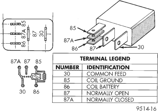
Compressor Clutch Relay
CIRCUIT TEST
For circuit descriptions and diagrams, refer to 8W-42 - Air Conditioning/Heater in Group 8W - Wiring Diagrams.
(1) The relay common feed terminal cavity (30) is connected to fused battery feed. There should be battery voltage at this cavity at all times. If OK, go to Step 2. If not OK, repair the open circuit to the PDC as required.
(2) The relay normally closed terminal (87A) is not used in this application. Go to Step 3.
(3) The relay normally open terminal cavity (87) is connected to the compressor clutch coil. There should be continuity between this cavity and the A/C compressor clutch relay output circuit cavity of the compressor clutch coil connector. If OK, go to Step 4. If not OK, repair the open circuit as required.
(4) The coil battery terminal cavity (86) is connected to fused ignition switch output. There should be battery voltage at this cavity with the ignition switch in the On position. If OK, go to Step 5. If not OK, repair the open circuit to the junction block as required.
(5) The coil ground terminal cavity (85) is switched to ground through the Powertrain Control Module (PCM). There should be continuity between this cavity and the A/C compressor clutch relay control circuit cavity of the PCM connector C (gray) at all times. If not OK, repair the open circuit as required.
HIGH PRESSURE CUT-OFF SWITCH
For circuit descriptions and diagrams, refer to 8W-42 - Air Conditioning/Heater in Group 8W - Wiring Diagrams.
(1) Verify that the refrigerant system is properly charged.
(2) Unplug the high pressure switch connector and test for continuity between the switch terminals. There should be continuity. If OK, refer to the wiring diagrams and repair the circuits as required. If not OK, replace the faulty switch.
HIGH SPEED BLOWER MOTOR RELAY
RELAY TEST
The high speed blower motor relay is located on the right end of the heater-A/C housing under the instrument panel. Remove the relay from its connector to perform the following tests:
(1) A relay in the de-energized position should have continuity between terminals 87A and 30, and no continuity between terminals 87 and 30. If OK, go to Step 2. If not OK, replace the faulty relay.
(2) Resistance between terminals 85 and 86 (electromagnet) should be 7565 ohms. If OK, go to Step 3. If not OK, replace the faulty relay. (3) Connect a battery to terminals 85 and 86. There should now be continuity between terminals 30 and 87, and no continuity between terminals 87A and 30. If OK, see the Relay Circuit Test in this group. If not OK, replace the faulty relay.
RELAY CIRCUIT TEST
(1) The relay common feed terminal cavity (30) is connected to battery voltage and should be hot at all times. If OK, go to Step 2.
(2) The relay normally closed terminal (87A) is connected to terminal 30 in the de-energized position, but is not used for this application. Go to Step 3.
(3) The relay normally open terminal (87) is connected to the common feed terminal (30) in the energized position. This terminal supplies battery voltage
High Speed Blower Motor Relay to the blower motor when the relay is energized by the ATC controller. There should be continuity between the cavity for relay terminal 87 and the high speed blower motor relay signal circuit cavity of the blower motor connector at all times. If OK, go to Step 4. If not OK, repair the open circuit to the blower motor as required.
(4) The coil battery terminal (86) is connected to battery voltage and should be hot at all times. If OK, go to Step 5. If not OK, repair the open circuit to the PDC fuse as required.
(5) The coil ground terminal (85) is connected to the electromagnet in the relay. It is grounded by the ATC controller when the blower switch is placed in the manual Hi blower speed position and/or when the ATC controller senses the need for Hi blower speed with the blower switch in the Hi Auto position. There should be continuity between the cavity for relay terminal 85 and the high speed blower motor relay control circuit cavity of the ATC controller connector at all times. If OK, see the ATC System tests in this group. If not OK, repair the open circuit as required.
LOW PRESSURE CYCLING CLUTCH SWITCH
Verify that the refrigerant system has the correct refrigerant charge. For circuit descriptions and diagrams, refer to 8W-42 - Air Conditioning/Heater in Group 8W - Wiring Diagrams.
(1) Unplug the low pressure cycling clutch switch connector from the switch on the accumulator, and install a jumper wire between the two connector cavities.
(2) Connect a manifold gauge set to the service ports.
(3) Place the heater-A/C mode control switch in any A/C position and start the engine.
(4) Check the continuity between the two terminals of the low pressure switch. There should be continuity with a suction pressure reading of 296 kPa
(43 psi) or above, and no continuity with a suction pressure reading of 172 kPa (25 psi) or below. If OK, test and repair the clutch control circuit as required. If not OK, replace the faulty switch.
REFRIGERANT SYSTEM LEAKS
WARNING: REVIEW THE WARNINGS AND CAU- TIONS IN THE FRONT OF THIS GROUP BEFORE LEAK TESTING THE SYSTEM.
If the air conditioning system is not cooling properly, determine if the refrigerant system is fullycharged. See A/C Performance in this group. If the refrigerant system is low or empty, a leak at a line, fitting, or component seal is likely. Fittings, lines, or components that appear to be oily indicate a possible refrigerant leak. To detect a leak in the refrigerant system, perform one of the following procedures:
SYSTEM EMPTY
(1) Evacuate the refrigerant system. See Refrigerant System Evacuate in this group.
(2) Connect and dispense 0.283 kPa (0.6 lbs. or 10 oz.) of R-134a refrigerant into the evacuated refrigerant system. See Refrigerant System Charge in this group.
(3) Position the vehicle in a wind-free work area. This will aid in detecting small leaks.
(4) With the engine not running, use a electronic R-134a leak detector and search for leaks. Move the leak detector probe slowly along the bottom side of all lines and fittings, because R-134a is heavier than air.
(5) To inspect the evaporator coil for leaks, insert the leak detector probe into the center panel outlet. Set the blower motor switch to the lowest speed (A/C) position, and the mode control switch in the Recirc mode.
SYSTEM LOW
(1) Position the vehicle in a wind-free work area. This will aid in detecting small leaks.
(2) Bring the refrigerant system up to operating temperature and pressure. This is done by allowing the engine to run with the air conditioning system on for five minutes.
(3) With the engine not running, use a electronic R-134a leak detector and search for leaks. Move the leak detector probe slowly along the bottom side of all lines and fittings, because R-134a is heavier than air.
(4) To inspect the evaporator coil for leaks, insert the leak detector probe into the center panel outlet. Set the blower motor switch to the lowest speed (A/C) position, and the mode control switch in the Recirc mode.
SERVICE PROCEDURES
REFRIGERANT RECOVERY
WARNING: REVIEW THE WARNINGS AND CAU- TIONS IN THE FRONT OF THIS GROUP BEFORE RECOVERING REFRIGERANT.
R-134a refrigerant is a hydrofluorocarbon (HFC) that does not contain chlorine. A R-134a refrigerant recovery/recycling station that meets SAE Standard J2210 must be used to recover the refrigerant. Refer to the operating instructions provided with the equipment for proper operation.
REFRIGERANT SYSTEM EVACUATE
WARNING: REVIEW THE WARNINGS AND CAU- TIONS IN THE FRONT OF THIS GROUP BEFORE EVACUATING THE SYSTEM.
If the refrigerant system has been open to the atmosphere, it must be evacuated before the system can be charged. Moisture and air mixed with the refrigerant will raise the compressor head pressure above acceptable operating levels. This will reduce the performance of the air conditioner and damage the compressor. Evacuating will boil the moisture out of the refrigerant system at near room temperature. To evacuate the refrigerant system, use the following procedure:
(1) Connect a suitable charging station and manifold gauge set to the vehicle.
(2) Open the low and high side valves and start the vacuum pump. When the suction gauge reads 88 kPa (26 in. Hg.) vacuum or greater, close all of the valves and turn off the vacuum pump. If the system fails to reach the specified vacuum, the system has a leak that must be corrected. If the system maintains the specified vacuum for five minutes, restart the vacuum pump. Then open the suction and discharge valves and evacuate an additional ten minutes.
(3) Close all of the valves. Turn off and disconnect the vacuum pump.
(4) The refrigerant system is now ready to be charged with refrigerant.
REFRIGERANT SYSTEM CHARGE
WARNING: REVIEW THE WARNINGS AND CAU- TIONS IN THE FRONT OF THIS GROUP BEFORE CHARGING THE REFRIGERANT SYSTEM.
After the system has been tested for leaks and evacuated, a refrigerant charge can be injected into the system. See Refrigerant Charge Capacity for the proper amount of the refrigerant charge. Charge the system using a recovery/recycling/charging station approved for R-134a refrigerant. This device must meet SAE Standard J2210. Refer to the instructions provided with the equipment for proper operation.
REFRIGERANT CHARGE CAPACITY
The R-134a system charge capacity is 0.8 kg (1.75 lbs.).
PARTIAL CHARGE METHOD
WARNING: REVIEW THE WARNINGS AND CAU- TIONS IN THE FRONT OF THIS GROUP BEFORE CHARGING THE REFRIGERANT SYSTEM.
The partial charge method is used to add a partial charge to a system that is low on refrigerant. To perform this procedure the evaporator inlet and outlet tube temperatures are measured. The temperature difference is measured with a temperature meter with one or two clamp-on thermocouple probes. The difference between the evaporator inlet and outlet tube temperatures will determine the amount of refrigerant needed.
Before adding a partial charge, check for refrigerant system leaks. See Refrigerant System Leaks in this group for the procedures. If a leak is found, make the necessary repairs before attempting a full or partial refrigerant system charge.
(1) Attach a manifold gauge set to the service ports.
(2) Attach the two clamp-on thermocouple probes to the inlet and outlet tubes of the evaporator coil.
(a) If a single thermocouple probe is used, attach the probe to the evaporator inlet tube just before the collar of the refrigerant line connector fitting. The probe must make contact with the bottom surface of the inlet tube.
(b) If dual thermocouple probes are used, attach probe 1 to the evaporator inlet tube, and probe 2 to the evaporator outlet tube. Attach both probes to the tubes just before the collar of the refrigerant line connector fittings. The probes must make contact with the bottom surfaces of the inlet and outlet tubes.
(3) Open all of the windows or doors of the passenger compartment. Set the air conditioning controls to A/C, Panel, Recirc (temperature control knob in the full cool position) and the blower motor switch on Hi.
(4) Start the engine and hold the engine idle speed at 1,000 rpm. Allow the engine to warm up to normal operating temperature.
(5) The compressor clutch may cycle, depending upon ambient temperature, humidity, and the refrigerant system charge level. If the compressor clutch cycles, unplug the connector from the low pressure cycling clutch switch on the accumulator. Install a jumper wire between the two cavities of the switch connector.
(6) Hold the engine idle speed at 1,000 rpm. (7) Allow three to five minutes for the refrigerant system to stabilize, then record the temperatures of the evaporator inlet and outlet tubes.
(a) If a single probe is used, record the temperature of the inlet tube. Then remove the probe from the inlet tube and attach it to the outlet tube just before the collar of the refrigerant line connector fitting. The probe must make contact with the bottom surface of the tube. Allow the thermocouple and meter time to stabilize, then record the temperature of the outlet tube. Subtract the inlet tube temperature reading from the outlet tube temperature reading.
(b) If dual probes are used, record the temperatures of both the inlet and outlet tubes. Then subtract the inlet tube temperature reading from the outlet tube temperature reading.
(8) See the Low Charge Determination chart to determine the additional charge required. If the measured temperature differential is higher than 22°C to 26°C (40°F to 47°F), add 0.4 kg (14 oz.) of refrigerant. (9) Allow three to five minutes for the refrigerant system to stabilize, then take a second set of thermocouple measurements. Record the temperature difference and see the Low Charge Determination chart to determine if an additional charge is required.
(10) Record the compressor discharge pressure. If the reading is higher than the pressure shown in the Compressor Discharge Pressure chart, the system could be overcharged. If the reading is equal to, or lower, than the pressure shown in the chart, continue with this procedure.
(11) EXAMPLE: The ambient temperature is 21°C (70°F). The evaporator inlet tube temperature is 12°C (54°F) and the evaporator outlet tube temperature is 10°C (50°F). Subtract the inlet tube temperature from the outlet tube temperature. The difference is -2°C (-4°F). With a -2°C (-4°F) temperature differential at 21°C (70°F) ambient temperature, the system is fully charged.
(12) Add enough refrigerant to bring the refrigerant system up to a full charge.
(13) Remove the jumper wire from the low pressure cycling clutch switch connector and plug the connector back into the switch.
REFRIGERANT OIL LEVEL
When an air conditioning system is assembled at the factory, all components (except the compressor) are refrigerant oil free. After the system has been charged and operated, the oil in the compressor is dispersed through the refrigerant system. The accumulator, evaporator, condenser, and compressor will retain a significant amount of oil.
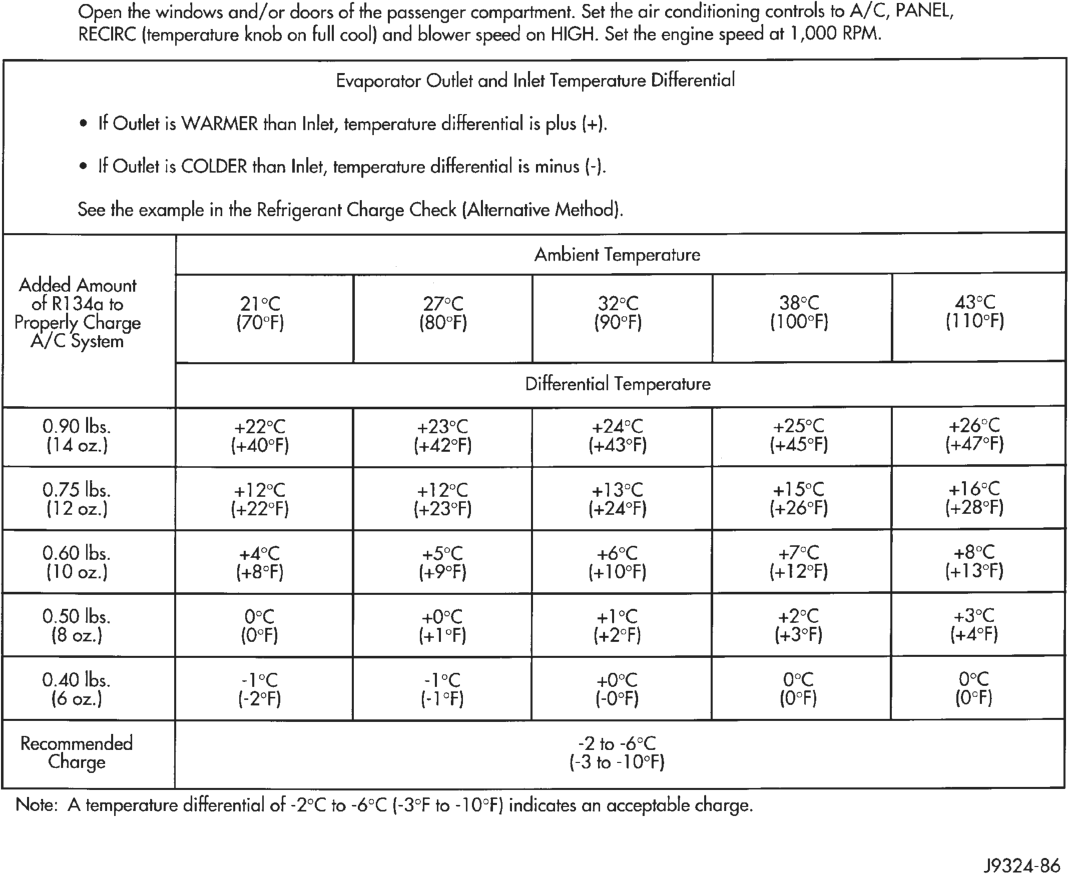
RECIRC (temperature knob on full cool) and blower speed on HIGH. Set the engine speed at 1,000 RPM.
Evaporator Outlet and Inlet Temperature Differential
® If Outlet is WARMER than Inlet, temperature differential is plus (+).
e If Outlet is COLDER than Inlet, temperature differential is minus (-).
See the example in the Refrigerant Charge Check (Alternative Method).
Added Amount
of R134a to 21°C 27°C 32°C 38°C A3°C
Properly Charge (70°F) (80°F) (90°F) (100°F} (1 10°F)
A/C System
Differential Temperature
0.90 lbs. +22°C +24°C +25°C +26°C
(14 oz.) (+40°F] (+42°F) (+43°F) (+45°F] (47°F)
0.75 lbs. +12°C +12°C +13°C +15°C +16°C
(12 oz.) (422°F) (423°F) (+24°F) (+26°F) (+28°F)
0.60 lbs. +4°C +5°C +6°C +7°C +8°C
(10 oz.) (+8°F) (+9°F} (+10°F) {+12°F) (+13°F)
0.50 lbs. O°c +0°C +1°C 42°C 43°C
(8 oz.) {O°F) (+1°F) (+2°F) (+3°F) (+4°F)
0.40 lbs. -1°C -1°C +0°C
(6 oz.) (-2°F) (-1°F) (-0°F) (0°F) (O°F)
Recommended -2 to -6°C
Charge (-3 to -10°F)
Noite: A temperature differential of -2°C to -6°C (-3°F to -10°F) indicates an acceptable charge.
J9324-86
Low Charge Determination

Compressor Discharge Pressure
It is important to have the correct amount of oil in the refrigerant system. This will ensure proper lubrication of the compressor. Too little oil will result in damage to the compressor. Too much oil will reduce the cooling capacity of the system.
It will not be necessary to check oil level in the compressor or to add oil, unless there has been an oil loss. This may be due to a rupture or leak from a refrigerant line, a compressor shaft seal, an evaporator, or a condenser. If a rupture occurs, add 1 ounce of oil to the system after the repair has been made. Oil loss at a leak point will be evident by the presence of a wet, shiny surface around the leak.
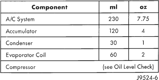
Refrigerant oil must be added when a accumulator, evaporator, or condenser are replaced. Refer to the Refrigerant Oil Capacities chart (Fig. 16). When a compressor is replaced, the oil must be drained from the old compressor and measured. Drain all the oil from the new compressor, then fill the new compressor with the same amount of oil that was drained out of the old compressor.
REMOVAL AND INSTALLATION
REFRIGERANT LINE COUPLERS
WARNING: REVIEW THE WARNINGS AND CAU- TIONS IN THE FRONT OF THIS GROUP BEFORE PERFORMING THE FOLLOWING OPERATION.
REMOVAL
(1) Recover the refrigerant from the refrigerant system as described in this group.
(2) Remove the secondary clip from the coupling. Fit the appropriate spring lock coupling tool from the A/C Tool Kit (Special Tool 6125) (Fig. 17).
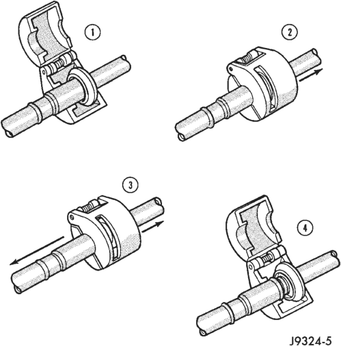
(3) Close the tool and push it into the open side of the cage to expand the garter spring and release the female fitting.
NOTE: The garter spring may not release if the tool is cocked while pushing it into the cage opening.
(4) After the garter spring is expanded, pull the fittings apart within the tool.
(5) Remove the tool from the disconnected coupling.
(6) Separate the two ends of the coupling.
INSTALLATION
(1) Check to ensure that the garter spring is in the cage of the male fitting. If the garter spring is missing, install a new spring by pushing it into the cage opening. If the garter spring is damaged, remove it from the cage with a small wire hook (DO NOT use a screwdriver) and install a new garter spring.
(2) Clean any dirt or foreign material from both halves of the coupling.
(3) Install new O-rings on the male fitting.
CAUTION: Use only the specified O-rings as they are made of a special material for the R-134a system. The use of any other O-ring may allow the connection to leak intermittently during vehicle operation.
(4) Lubricate the male fitting and O-ring, and the inside of the female fitting with clean R-134a (SP20 PAG) refrigerant oil.
(5) Fit the female fitting to the male fitting and push together until the garter spring snaps over the flared end of the female fitting.
(6) Ensure the coupling is fully engaged by pulling back on the lines on either side of the coupling.
(7) Install the secondary clip on the coupling.
COMPRESSOR
The compressor may be removed and repositioned without disconnecting the refrigerant lines or discharging the refrigerant system. Discharging is not necessary if servicing the compressor clutch or clutch coil, the engine, the cylinder head, or the generator.
WARNING: REVIEW THE WARNINGS AND CAU- TIONS IN THE FRONT OF THIS GROUP BEFORE PERFORMING THE FOLLOWING OPERATION.
REMOVAL
(1) Disconnect and isolate the battery negative cable.
(2) Loosen and remove the serpentine drive belt. Refer to Group 7 - Cooling System for the procedures.
(3) Disconnect the compressor clutch coil wiring.
(4) Recover the refrigerant from the refrigerant system as described in this group.
(5) Remove the refrigerant lines from the compressor. Install plugs in, or tape over, all of the open refrigerant fittings.
(6) Remove the compressor mounting bolts, and lift the compressor from the mounting bracket.
INSTALLATION
NOTE: If a replacement compressor is being installed, be certain to check the oil level. See Refrigerant Oil Level in this group.
(1) If the compressor mounting bracket was removed, install the bracket to the engine. Tighten the mounting bolts to 27 N·m (20 ft. lbs.).
(2) Install the compressor on the mounting bracket. Tighten the bolts to 27 N·m (20 ft. lbs.).
(3) Remove the tape or plugs from all of the refrigerant fittings, and install the refrigerant lines on the compressor.
(4) Install the serpentine drive belt. Refer to Group 7 - Cooling System for the procedures.
(5) Connect the compressor clutch coil wiring. (6) Connect the battery negative cable. (7) Evacuate and charge the refrigerant system as described in this group.
COMPRESSOR CLUTCH
The refrigerant system can remain fully-charged during compressor clutch, pulley, or coil replacement. The compressor clutch can be serviced in the vehicle.
REMOVAL
(1) Disconnect and isolate the battery negative cable.
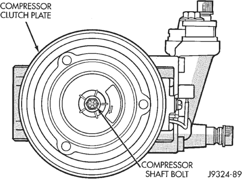
(2) Remove the compressor shaft bolt (Fig. 18). A band-type oil filter wrench may be used to aid in securing the clutch during bolt removal.
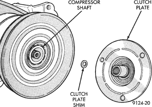
(3) Tap the clutch plate with a plastic mallet to release it from the splines on the compressor shaft. Remove clutch plate and shim(s) from the compressor shaft (Fig. 19).
CAUTION: Do not pry between the clutch plate assembly and the pulley to remove the front plate. This may damage the front plate assembly.
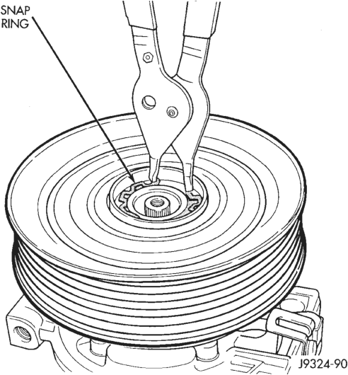
(4) Remove the pulley retaining snap ring with snap ring pliers (Special Tool C-4574) and slide the pulley assembly off of the compressor (Fig. 20).
(5) Remove the screw and retainer from the clutch coil lead wire on the compressor front housing.
(6) Remove the snap ring from the compressor hub and remove the clutch field coil (Fig. 21). Slide the clutch field coil off of the compressor hub.
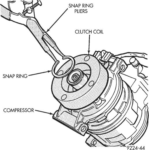
INSPECTION
Examine the friction surfaces of the clutch pulley and the front plate for wear. The pulley and front plate should be replaced if there is excessive wear or scoring.
If the friction surfaces are oily, inspect the shaft and nose area of the compressor for oil. Remove the felt from the front cover. If the felt is saturated with oil, the shaft seal is leaking and the compressor must be replaced.
Check the clutch pulley bearing for roughness or excessive leakage of grease. Replace the bearing, if required.
INSTALLATION
(1) Align the dowel pin on the back of the clutch field coil with the hole in the compressor front housing and press the field coil into place.
(2) Install the clutch coil wire lead retaining clip on the compressor front housing and tighten the retaining screw.
(3) Install the clutch field coil and snap ring with snap ring pliers (Special Tool C-4574). The bevel side of the snap ring must be facing outward. Also, both eyelets of the snap ring must be to the right or left of the pin on the compressor. Press the snap ring to make sure it is properly seated in the groove.
CAUTION: If the snap ring is not fully seated in the groove it will vibrate out, resulting in a clutch failure and severe damage to the front housing of the compressor.
(4) Install the pulley assembly onto the compressor. If necessary, place a block of wood on the friction surface and tap gently with a hammer (Fig. 22).
CAUTION: Do not mar the pulley friction surface.
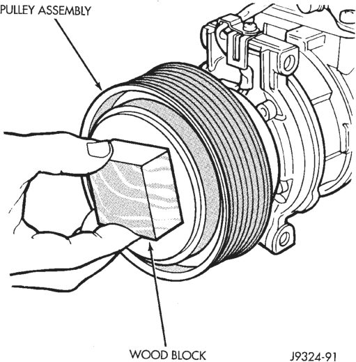
(5) Install the pulley assembly retaining snap ring (bevel side outward) with snap ring pliers (Special Tool C-4574). Press the snap ring to make sure it is properly seated in the groove.
(6) If the original front plate assembly and pulley assembly are to be reused, the old shim(s) can be used. If not, place a stack of shim(s) equal to the old shim(s) on the shaft against the shoulder.
(7) Install the front plate assembly onto the shaft. (8) With the front plate assembly tight against the shim(s), measure the air gap between the front plate and the pulley face with feeler gauges. The air gap should be between 0.35 - 0.65 mm (.014 - .026 in.). If the proper air gap is not obtained, add or subtract shims as needed until the desired air gap is obtained.
(9) Install the compressor shaft bolt. Tighten the bolt to 13 N·m (115 in. lbs.).
NOTE: The shims may compress after tightening the shaft bolt. Check the air gap in four or more places to verify the air gap is still correct. Spin the pulley before performing a final check of the air gap.
(10) Connect the battery negative cable.
CLUTCH BREAK-IN
After a new compressor clutch has been installed, cycle the compressor clutch approximately 20 times (5 seconds on, then 5 seconds off). During this procedure, set the heater-A/C control to the A/C (Recirc) mode, the blower motor switch in the highest speed position, and the engine speed at 1500 - 2000 rpm. This procedure (burnishing) will seat the opposing friction surfaces and provide a higher compressor clutch torque capability.
HIGH PRESSURE CUT-OFF SWITCH
REMOVAL
(1) Disconnect and isolate the battery negative cable.
(2) Unplug the wiring connector from the switch (Fig. 23).
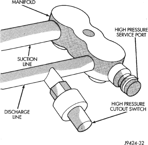
(3) Unscrew the switch from the discharge line fitting.
INSTALLATION
(1) Install and tighten the switch. (2) Plug the wiring connector into the switch. (3) Connect the battery negative cable.
HIGH PRESSURE RELIEF VALVE
WARNING: REVIEW THE WARNINGS AND CAU- TIONS IN THE FRONT OF THIS GROUP BEFORE PERFORMING THE FOLLOWING OPERATION.
REMOVAL
(1) Disconnect and isolate the battery negative cable.
(2) Recover the refrigerant from the refrigerant system as described in this group.
(3) Turn the relief valve counterclockwise to remove it from the compressor manifold (Fig. 24).
(4) Either install a plug in, or tape over, the open fitting on the compressor manifold.
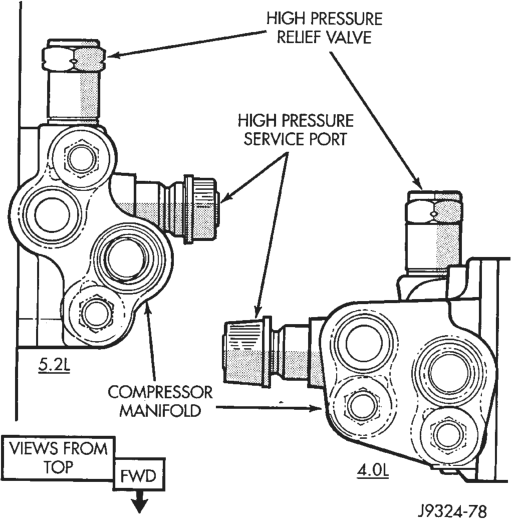
INSTALLATION
(1) Remove the plug or tape from the compressor manifold fitting.
(2) Install the high pressure relief valve in the compressor manifold.
(3) Evacuate and charge the refrigerant system as described in this group.
(4) Connect the battery negative cable.
CONDENSER
WARNING: REVIEW THE WARNINGS AND CAU- TIONS IN THE FRONT OF THIS GROUP BEFORE PERFORMING THE FOLLOWING OPERATION.
CAUTION: When removing the condenser note the locations of all of the radiator and condenser air seals. These seals are used to direct air through the condenser and radiator. They must be installed in their original locations to prevent engine overheating (Fig. 25).
Fig. 25 Air Seals
REMOVAL
(1) Disconnect and isolate the battery negative cable.
(2) Recover the refrigerant from the refrigerant system as described in this group.
(3) Disconnect the refrigerant lines from the condenser. Install plugs in, or tape over, all of the open refrigerant fittings.
(4) Remove the radiator grille panel. Refer to Group 23 - Body Components for the procedures.
(5) Remove the upper bolts from the two radiator braces (Fig. 26).
(6) Remove the two nuts securing the radiator to the crossmember (Fig. 27).
(7) Reach through the grille opening and remove the bolt securing the lower hood latch support to the lower front crossmember.
(8) The radiator upper crossmember can be adjusted left or right through the use of its slotted mounting holes. Before removal, mark the original position of the crossmember.
(9) Remove the remaining bolts securing the radiator upper crossmember to the body. Do not remove the hood latch or hood latch cable from the crossmember. Lift the crossmember straight up and lay it to the side.
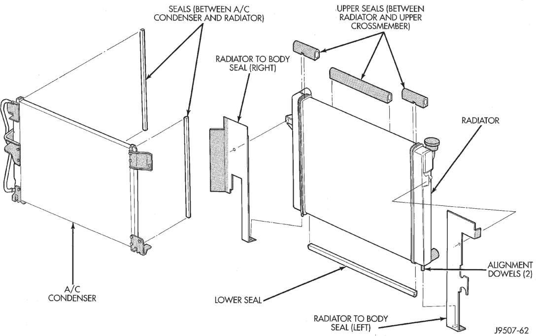
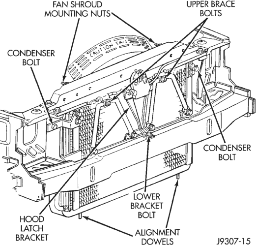
(10) Remove the four bolts securing the lower condenser.
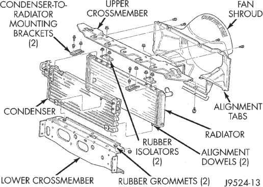
(11) Remove the two bolts securing the upper condenser.
(12) Carefully remove the condenser from the vehicle.
INSTALLATION
(1) Carefully position the condenser in the vehicle. (2) Install and tighten the two bolts securing the upper condenser.
(3) Install and tighten the four bolts securing the lower condenser.
(4) Align the radiator upper crossmember with the scribe marks. Install and tighten the bolts securing the radiator upper crossmember to the body.
(5) Install and tighten the nuts securing the radiator to the upper crossmember.
(6) Reach through the grille opening to install and tighten the bolt securing the lower hood latch support to the lower front crossmember.
(7) Install and tighten the two bolts securing the radiator braces to the upper radiator crossmember.
(8) Install the grille panel. (9) Remove the plugs or tape from the open refrigerant line fittings and connect the refrigerant lines to the condenser.
(10) Evacuate the refrigerant system as described in this group.
(11) Add 1 ounce of refrigerant oil to the refrigerant system if the condenser was replaced.
(12) Charge the refrigerant system as described in this group.
(13) Connect the battery negative cable.
FIXED ORIFICE TUBE
The fixed orifice tube is located in the liquid line near the condenser. The orifice has filter screens on the inlet and outlet ends of the tube body. If the fixed orifice tube is faulty or plugged, the liquid line must be replaced.
WARNING: REVIEW THE WARNINGS AND CAU- TIONS IN THE FRONT OF THIS GROUP BEFORE PERFORMING THE FOLLOWING OPERATION.
REMOVAL
(1) Disconnect and isolate the battery negative cable.
(2) Recover the refrigerant from the refrigerant system as described in this group.
(3) Disconnect the refrigerant line couplers at the condenser outlet line and the evaporator inlet line.
(4) Remove the liquid line from the vehicle.
INSTALLATION
(1) Install the fixed orifice tube in the liquid line. (2) Connect the liquid line at the evaporator inlet line and the condenser outlet line.
(3) Evacuate and charge the refrigerant system as described in this group.
(4) Connect the battery negative cable.
ACCUMULATOR
WARNING: REVIEW THE WARNINGS AND CAU- TIONS IN THE FRONT OF THIS GROUP BEFORE PERFORMING THE FOLLOWING OPERATION.
REMOVAL
(1) Disconnect and isolate the battery negative cable.
(2) Recover the refrigerant from the refrigerant system as described in this group.
(3) Disconnect the refrigerant lines from the compressor and the evaporator. Install plugs in, or tape over, all of the open refrigerant fittings.
(4) Unplug the wire harness from the low pressure cycling clutch switch (Fig. 28).
(5) Loosen the support bracket screw. (6) Remove the accumulator.
INSTALLATION
NOTE: Add 4 ounces of refrigerant oil to the accumulator if it is being replaced.
(1) Install the accumulator in the support bracket. (2) Tighten the support bracket screw. (3) Plug the wire harness into the low pressure cycling clutch switch.
(4) Remove the plugs or tape from the refrigerant line fittings. Connect the refrigerant lines to the compressor and the evaporator.
(5) Evacuate and charge the refrigerant system as described in this group.
(6) Connect the battery negative cable.
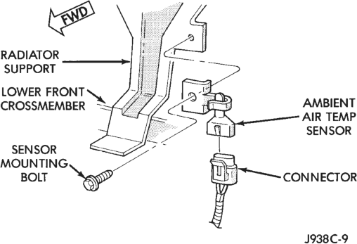
LOW PRESSURE CYCLING CLUTCH SWITCH
(1) Disconnect and isolate the battery negative cable.
(2) Unplug the wire harness connector from the switch.
(3) Unscrew the switch from the fitting on the accumulator.
(4) Reverse the removal procedures to install.
AMBIENT TEMPERATURE SENSOR
(1) Disconnect and isolate the battery negative cable.
(2) Remove the radiator grille unit. Refer to Group 23 - Body Components for the procedure. (3) Locate the temperature sensor, on the radiator support behind the grille (Fig. 29).
(4) Unplug the temperature sensor wiring connector.
(5) Remove the temperature sensor mounting bolt and remove the sensor.
(6) Reverse the removal procedures to install.
HEATER-A/C CONTROL
WARNING: ON VEHICLES EQUIPPED WITH AIR- BAGS, REFER TO GROUP 8M - PASSIVE RESTRAINT SYSTEMS BEFORE ATTEMPTING STEERING WHEEL, STEERING COLUMN, OR INSTRUMENT PANEL COMPONENT DIAGNOSIS OR SERVICE. FAILURE TO TAKE THE PROPER PRE- CAUTIONS COULD RESULT IN ACCIDENTAL AIR- BAG DEPLOYMENT AND POSSIBLE PERSONAL INJURY.
REMOVAL
(1) Disconnect and isolate the battery negative cable.
(2) Using a trim stick or other suitable wide flatbladed tool, pry gently around the edges of the right switch pod bezel and remove the bezel.
(3) Remove the three screws securing the heater- A/C control to the instrument panel (Fig. 30).
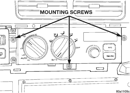
(4) Pull the heater-A/C control out from the instrument panel far enough to access the connectors on the back of the control.
(5) Unplug the electrical and/or vacuum connectors from the back of the heater-A/C control (Fig. 31).
(6) Remove the heater-A/C control from the instrument panel.
INSTALLATION
(1) Connect the vacuum and electrical connectors to the heater-A/C control.
(2) Install the heater-A/C control to the instrument panel with three screws.
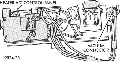
(3) Install the right switch pod bezel. (4) Connect the battery negative cable.
SOLAR SENSOR
This sensor is used only on models with the optional ATC system.
WARNING: ON VEHICLES EQUIPPED WITH AIR- BAGS, REFER TO GROUP 8M - PASSIVE RESTRAINT SYSTEMS BEFORE ATTEMPTING STEERING WHEEL, STEERING COLUMN, OR INSTRUMENT PANEL COMPONENT DIAGNOSIS OR SERVICE. FAILURE TO TAKE THE PROPER PRE- CAUTIONS COULD RESULT IN ACCIDENTAL AIR- BAG DEPLOYMENT AND POSSIBLE PERSONAL INJURY.
REMOVAL
(1) Disconnect and isolate the battery negative cable.
(2) Using a trim stick or other suitable wide flatbladed tool, pry gently along the edge of the instrument panel cowl top trim panel to release the snap clips (Fig. 32).
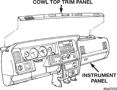
(3) Lift the cowl top trim panel far enough to reach underneath it to access the solar sensor, which is located between the right and center defroster outlets.
(4) Use a twisting motion to remove the solar sensor from the cowl top trim panel (Fig. 33).
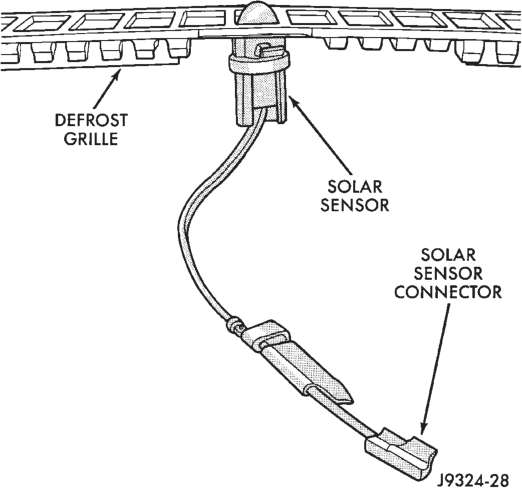
(5) Pull the sensor out far enough to access the wiring connector and unplug it from the instrument panel wiring.
INSTALLATION
(1) Connect the solar sensor connector. (2) Install the solar sensor into the cowl top trim panel.
(3) Press the cowl top trim panel down until the snap clips engage in the top of the instrument panel.
(4) Connect the battery negative cable.
IN-VEHICLE TEMPERATURE SENSOR
This sensor is used only on models with the optional ATC system.
WARNING: ON VEHICLES EQUIPPED WITH AIR- BAGS, REFER TO GROUP 8M - PASSIVE RESTRAINT SYSTEMS BEFORE ATTEMPTING STEERING WHEEL, STEERING COLUMN, OR INSTRUMENT PANEL COMPONENT DIAGNOSIS OR SERVICE. FAILURE TO TAKE THE PROPER PRE- CAUTIONS COULD RESULT IN ACCIDENTAL AIR- BAG DEPLOYMENT AND POSSIBLE PERSONAL INJURY.
REMOVAL
(1) Disconnect and isolate the battery negative cable.
(2) Remove the lower right instrument panel module. Refer to Group 8E - Instrument Panel Systems for the procedures.
(3) Disconnect the aspirator hose at the in-line splice connector near the right side floor pan transmission tunnel under the instrument panel (Fig. 34).
(4) (Fig. 34).
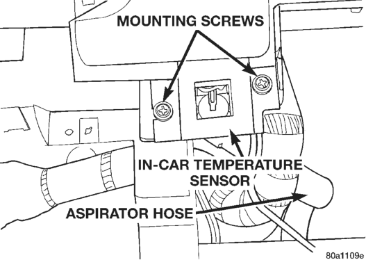
(5) Reach behind the sensor and unplug the wiring connector.
(6) Remove the two screws securing the sensor assembly to the instrument panel.
(7) Remove the sensor assembly from the instrument panel.
INSTALLATION
(1) Insert the in-vehicle temperature sensor into the instrument panel.
(2) Install the two sensor mounting screws. (3) Connect the sensor wiring. (4) Connect the aspirator hose to the in-line splice connector.
(5) Install the lower right instrument panel module. Refer to Group 8E - Instrument Panel Systems for the procedures.
BLOWER MOTOR
REMOVAL
(1) Disconnect and isolate the battery negative cable.
(2) Disconnect the blower motor cooling tube (Fig. 35). (3) Remove the blower motor wiring from the retainer. Unplug the wiring connector.
(4) Remove the blower motor and wheel assembly mounting screws.
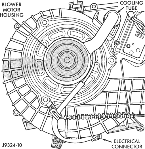
(5) Remove the blower motor and wheel. (6) Remove the blower motor wheel retainer clip and remove the wheel from the blower motor shaft (Fig. 36).
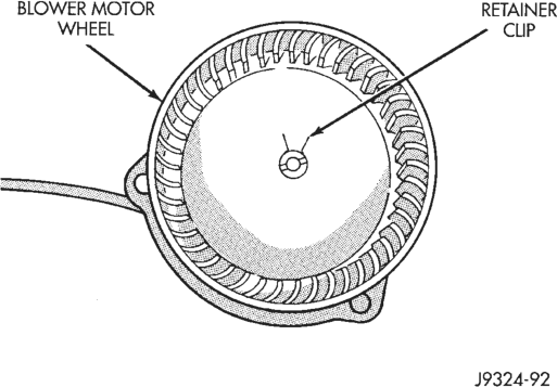
INSTALLATION
(1) Press the blower motor wheel onto the blower motor shaft. Be sure the flat on the blower motor shaft lines up with the flat inside the wheel.
(2) Install the retainer clip. The ears of the retainer clip must be over the flat surface on the motor shaft.
(3) Be certain that the blower motor seal is installed on the blower motor housing (Fig. 37).
(4) Install the blower motor.
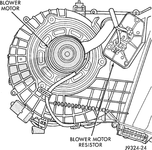
(5) Install and tighten the blower motor mounting screws.
(6) Connect the wiring connector and install the wiring into the retainer.
(7) Connect the blower motor cooling tube. (8) Connect the battery negative cable.
BLOWER MOTOR RESISTOR/POWER MODULE
REMOVAL
(1) Disconnect and isolate the battery negative cable.
(2) Unplug the blower motor resistor/power module connector.
(3) Remove the resistor/power module retaining screws.
(4) Remove the blower motor resistor/power module (Fig. 38).
INSTALLATION
(1) Install the blower motor resistor/power module. Install and tighten the screws.
(2) Connect the resistor/module connector. (3) Connect the battery negative cable.
HIGH SPEED BLOWER MOTOR RELAY
This relay is used only on models equipped with the optional ATC system.
REMOVAL
(1) Disconnect and isolate the battery negative cable.
(2) Locate the relay near the right end of the heater-A/C housing under the instrument panel (Fig. 39).
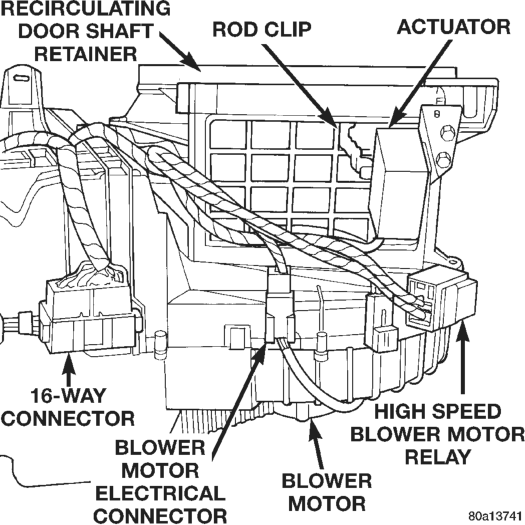
(3) Unclip the relay connector from the side of the heater-A/C housing.
(4) Unplug the relay from the connector.
INSTALLATION
(1) Align the relay terminals with the cavities in the relay connector.
(2) Push the relay firmly into the connector. (3) Clip the relay connector back on the side of the heater-A/C housing.
(4) Connect the battery negative cable.
TEMPERATURE/BLEND-AIR DOOR MOTOR
The temperature/blend air door motor is located under the instrument panel and can be removed from the passenger compartment.
REMOVAL
(1) Disconnect and isolate the battery negative cable.
(2) Unplug the wire connector from the motor (Fig. 40).
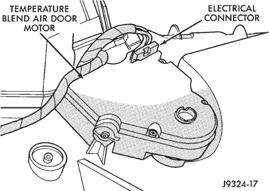
(3) Remove the screws securing the motor to the heater-A/C housing.
(4) Remove the temperature/blend air door motor.
INSTALLATION
(1) Position the motor over the door connection. (2) Install and tighten the screws securing the motor to the heater-A/C housing.
(3) Connect the wire harness to the motor. (4) Connect the battery negative cable.
DUCTS AND OUTLETS
DEFROSTER DUCT
(1) Remove the instrument panel from the vehicle as described in Group 8E - Instrument Panel Systems.
(2) Remove three screws securing the defroster duct to the instrument panel armature.
(3) Remove the defroster duct. (4) Reverse the removal procedures to install.
DEMISTER DUCTS
(1) Remove the defroster duct as described in this group.
(2) Remove the four screws securing the demister ducts to the instrument panel armature.
(3) Remove the demister ducts. (4) Reverse the removal procedures to install.
PANEL DUCTS
(1) Remove the demister ducts as described in this group.
(2) Remove the four screws securing the panel ducts to the instrument panel armature.
(3) Remove the panel ducts. (4) Reverse the removal procedures to install.
FLOOR DUCTS
(1) Remove the center floor console as described in Group 23 - Body Components.
(2) Remove the right front seat as described in Group 23 - Body Components.
(3) Remove the passenger side front door opening trim as described in Group 23 - Body Components.
(4) Roll back the floor carpeting. (5) Remove the nut securing the floor duct to the stud on the floor pan transmission tunnel (Fig. 41).
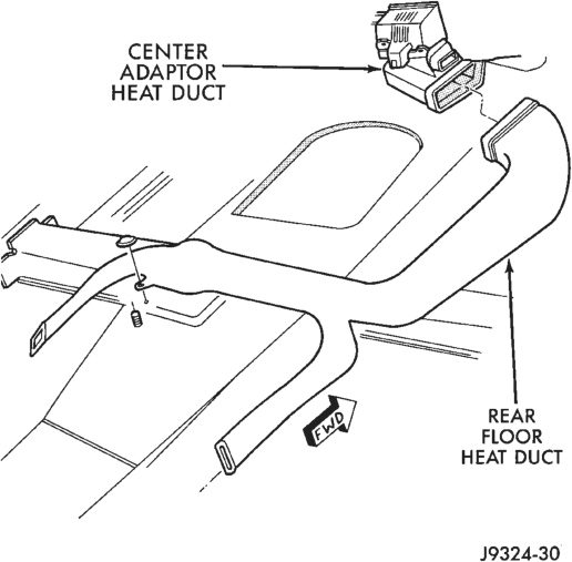
(6) Disconnect the floor duct from the center adaptor duct.
(7) Remove the floor duct from the vehicle. (8) Reverse the removal procedures to install.
DEMISTER OUTLETS
(1) Using a trim stick or other suitable wide flatbladed tool, pry the edge of the outlet away from the instrument panel top pad.
(2) To install, push the outlet firmly into the hole in the instrument panel top pad.
PANEL OUTLETS
The left and center panel outlets are only serviced as part of the instrument cluster bezel unit. The right panel outlets are available for service.
(1) Remove the instrument panel top pad as described in Group 8E - Instrument Panel Systems.
(2) Remove the two screws securing each outlet to the top pad.
(3) Remove the outlet from the top pad. (4) Reverse the removal procedures to install.
PANEL/DEFROST DOOR
REMOVAL
(1) Disconnect and isolate the battery negative cable. (2) Remove the instrument panel as described in Group 8E - Instrument Panel Systems.
(3) Disconnect the panel/defrost door actuating rod (Fig. 42) or (Fig. 43).
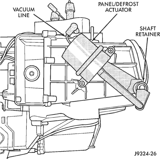
(4) Pry the panel/defrost door pivot shaft retainer from the pivot shaft.
(5) Remove the door through the top opening.
INSTALLATION
(1) Install the panel/defrost door through the top opening and place into position in the heater-A/C housing.
(2) Press the door pivot shaft retainer onto the pivot shaft.
(3) Connect the actuating rod and rod clip to the shaft retainer.
(4) Install the instrument panel as described in Group 8E - Instrument Panel Systems.
(5) Connect the battery negative cable.
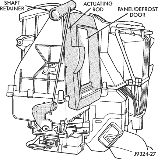
RECIRCULATING AIR DOOR ACTUATOR
REMOVAL (1) Disconnect and isolate the battery negative cable.
(2) Remove the instrument panel as described in Group 8E - Instrument Panel Systems.
(3) Disconnect the actuator vacuum line (Fig. 44) or electrical connector (Fig. 45).
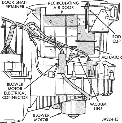
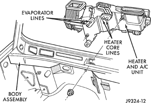
(4) Disconnect the actuating rod clip. (5) Remove the screws securing the actuator to the heater-A/C housing.
(6) Remove the actuator from the heater-A/C housing.
INSTALLATION
(1) Position the actuator on the heater-A/C housing.
(2) Install and tighten the screws securing the actuator to the housing.
(3) Connect the actuating rod and clip to the door lever.
(4) Connect the vacuum line or the electrical connector to the actuator.
(5) Install the instrument panel as described in Group 8E - Instrument Panel Systems.
(6) Connect the battery negative cable.
HEATER-A/C HOUSING
REMOVAL
(1) Disconnect and isolate the battery negative cable.
(2) Recover the refrigerant from the refrigerant system as described in this group.
(3) Disconnect the refrigerant lines from the evaporator tubes (Fig. 46). Install plugs in, or tape over, all of the open refrigerant fittings.
(4) Drain the cooling system. Refer to Group 7 - Cooling System for the procedures.
(5) Disconnect the heater hoses from the heater core tubes.
(6) Remove the coolant reserve/overflow bottle.
(7) Remove the Powertrain Control Module (PCM) and set aside. Do not unplug the PCM connectors.
(8) Remove the heater-A/C housing mounting nuts from the studs on the engine compartment side of the dash panel.
(9) Remove the instrument panel. Refer to Group 8E - Instrument Panel Systems for the procedures. (10) Disconnect the rear floor heat duct from the center adaptor (Fig. 47).
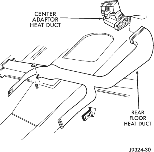
(11) Unplug the heater-A/C housing electrical connections.
(12) Remove the heater-A/C housing mounting nuts from the studs on the passenger compartment side of the dash panel (Fig. 48).
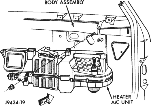
(13) Remove the heater-A/C housing from the vehicle.
INSTALLATION
(1) Position the heater-A/C housing to the dash panel. Be sure the drain tube is positioned in the dash panel drain hole.
(2) Install the mounting nuts to the studs on the passenger compartment side of the dash panel. Tighten the nuts to 4.5 N·m (40 in. lbs.).
(3) Install the mounting nuts to the studs on the engine compartment side of the dash panel. Tighten the nuts to 7 N·m (60 in. lbs.).
(4) Connect the heater hoses to the heater core tubes.
(5) Unplug or remove the tape from the refrigerant fittings, and connect the refrigerant lines to the evaporator tubes.
(6) Install the coolant reserve/overflow bottle. (7) Install the PCM. (8) Connect the rear floor heat duct to the center adaptor. Check that the carpet is not interfering with any duct outlets.
(9) Connect the heater-A/C housing electrical connectors.
(10) Install the instrument panel. Refer to Group 8E - Instrument Panel Systems for the procedures. (11) Fill the cooling system. Refer to Group 7 - Cooling System for the procedures.
(12) Evacuate and charge the refrigerant system as described in this group.
(13) Start the vehicle and check for proper operation of the heating and air conditioning systems.
HEATER CORE
REMOVAL
(1) Remove the heater-A/C housing as described in this group.
(2) Remove the heater core retaining screws. (3) Pull the heater core straight out of the housing (Fig. 49).
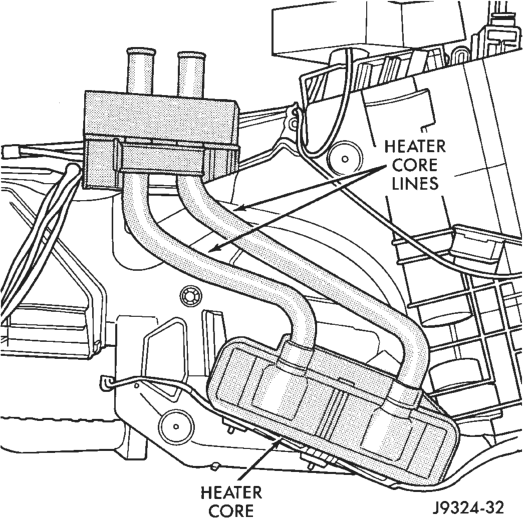
INSTALLATION
(1) Install the heater core into the housing. (2) Position the clips over the heater core tubes. Install and tighten the screws.
(3) Install the heater-A/C housing as described in this group.
EVAPORATOR COIL
REMOVAL
(1) Remove the heater-A/C housing as described in this group.
(2) Turn the heater-A/C housing upside down. (3) Remove the retaining screws holding the two housing halves together. Remove the center heat duct adaptor and remove the screw.
(4) Carefully turn the heater-A/C housing over. Remove the top half of the housing (Fig. 50).
(5) Remove the evaporator from the housing.
INSTALLATION
(1) Position the evaporator in the bottom half of the heater-A/C housing.
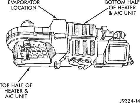
Down)
(2) Position the top half of the heater-A/C housing over the bottom half. Carefully turn the housing over. Install and tighten the retaining screws.
(3) Snap on the center heat duct adaptor. (4) Install the heater-A/C housing as described in this group.
NOTE: If the evaporator was replaced, add 2 ounces of refrigerant oil to the refrigerant system.
HEAT/DEFROST DOOR ACTUATOR
This actuator is used only on models equipped with the standard manual temperature control system.
REMOVAL
(1) Remove the heater-A/C housing from the vehicle as described in this group.
(2) Turn the heater-A/C housing upside down. (3) Disconnect the vacuum line from the actuator (Fig. 51).
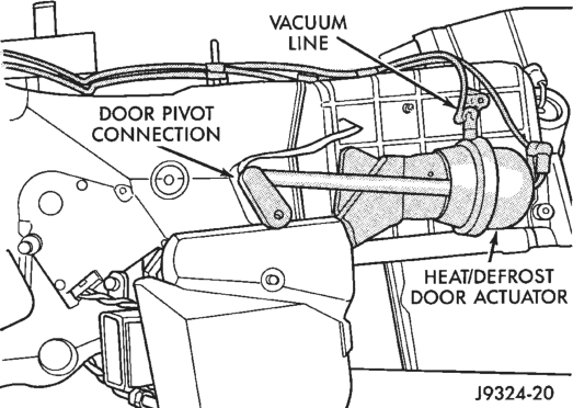
(4) Separate the door pivot connection from the door pivot pin.
(5) Remove the retaining screws. (6) Remove the heat/defrost door actuator.
INSTALLATION
(1) Install the heat/defrost door actuator. (2) Install and tighten the retaining screws. (3) Press the door pivot connection onto the door pivot pin.
(4) Connect the vacuum line. (5) Install the heater-A/C housing into the vehicle.
PANEL/DEFROST DOOR ACTUATOR
This actuator is used only on models equipped with the standard manual temperature control system.
REMOVAL
(1) Remove the heater-A/C housing as described in this group.
(2) Disconnect the vacuum line from the actuator (Fig. 52).
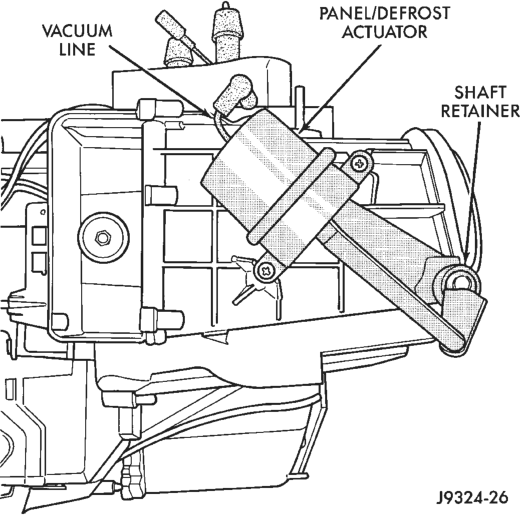
(3) Separate the actuator door pivot connection from the door pivot pin.
(4) Remove the retaining screws. (5) Remove the panel/defrost door actuator.
INSTALLATION
(1) Install the panel/defrost door actuator. (2) Install and tighten the retaining screws. (3) Press the actuator door pivot connection onto the door pivot pin.
(4) Connect the vacuum line to the actuator.
(5) Install the heater-A/C housing as described in this group. HEAT/DEFROST - PANEL/DEFROST DOOR MOTOR
This motor is used only on models equipped with the optional Automatic Temperature Control (ATC) system. REMOVAL
(1) Disconnect and isolate the battery negative cable.
(2) Remove the two bolts that secure the center instrument panel suppport bracket to the left side of the floor pan transmission tunnel.
(3) Remove the two bolts that secure the center instrument panel support bracket to the instrument panel.
(4) Remove the center instrument panel support bracket from the vehicle.
(5) Unplug the wire harness connector from the motor (Fig. 53).
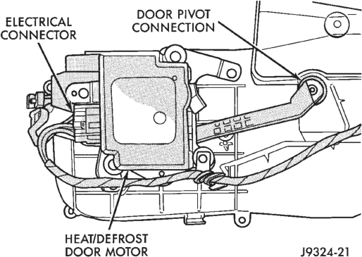
(6) Remove the three screws that secure the motor to the bottom of the heater/A/C housing.
(7) Remove the motor from the housing. INSTALLATION
(1) Position the heat/defrost-panel/defrost door motor to the bottom of the heater-A/C housing.
(2) Install and tighten the three screws that secure the motor to the housing.
(3) Plug in the wire harness connector to the motor.
(4) Position the center instrument panel support bracket to the instrument panel.
(5) Install and tighten the two bolts that secure the center instrument panel support bracket to the instrument panel.
(6) Install and tighten the two bolts that secure the center instrument panel support bracket to the left side of the floor pan transmission tunnel.
(7) Connect the battery negative cable.
HEAT/DEFROST DOOR
REMOVAL
(1) Remove the heater-A/C housing as described in this group.
(2) Turn the heater-A/C housing upside down. (3) Separate the actuator door pivot connection from the door pivot pin.
(4) Disconnect the vacuum line from the actuator or unplug the wiring connector from the motor, as equipped.
(5) Remove the retaining screws holding the two halves of the heater-A/C housing together. Remove the center heat duct adaptor and remove the screw.
(6) Remove the bottom half of the heater-A/C housing.
(7) Remove the heat/defrost door.
INSTALLATION
(1) Position the door pivot pin in the pivot hole. (2) Press the actuator door pivot connection onto the door pivot pin.
(3) Position the top half of the heater-A/C housing onto the bottom. Be certain the door pivot pins align with the pivot holes.
(4) Carefully turn the heater-A/C housing over. Install and tighten the screws.
(5) Snap on the center heat duct adaptor. (6) Connect the vacuum line to the actuator or the wiring to the motor, as equipped.
(7) Install the heater-A/C housing.
RECIRCULATING AIR DOOR
REMOVAL
(1) Remove the heater-A/C housing as described in this group.
(2) Disconnect the actuator rod clip. (3) Pry the recirculating air door shaft retainer from the shaft.
(4) Remove the recirculating air door through the top opening.
INSTALLATION
(1) Install the recirculating air door through the top opening and position in place.
(2) Press the recirculating air door shaft retainer onto the shaft.
(3) Connect the rod and rod clip to the door lever. (4) Install the heater-A/C housing as described in this group.
TEMPERATURE/BLEND-AIR DOOR
REMOVAL
(1) Remove the heater-A/C housing as described in this group.
(2) Turn the heater-A/C housing upside down. (3) Remove the screws holding the two housing halves together. Remove the center heat duct adaptor and remove the screw.
(4) Remove the bottom half of the heater-A/C housing.
(5) Remove the temperature control door (Fig. 54). (6) To reinstall the door-to-motor pivot connection, the motor must be removed from the heater-A/C housing as described in this group.
INSTALLATION
(1) If the door was removed, install the removed motor to the pivot connection. Position the motor on the heater-A/C housing and tighten the screws.
(2) Install the temperature control door. (3) Position the top half of the heater-A/C housing onto the bottom half. Be sure the door pivot pins align with the pivot holes.
(4) Carefully turn the heater-A/C housing over. Install and tighten the screws.
(5) Snap on the center heat duct adaptor.
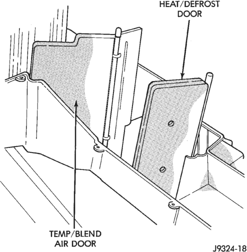
(6) Install the heater-A/C housing as described in this group.