Fuel System — part 2 of 2 — 1996 Jeep Grand Cherokee ZJ Service Manual
← Contents 1 2
Pages 1125–1127 · 3 pages · 0 words repaired
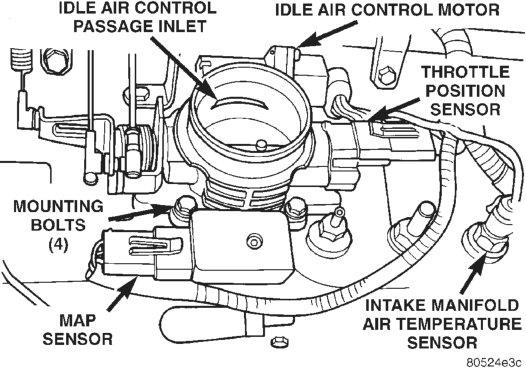
INTAKE MANIFOLD AIR TEMPERATURE SENSOR— 4.0L ENGINE The intake manifold air temperature sensor is installed into the intake manifold plenum near the throttle body (Fig. 86).
REMOVAL
(1) Disconnect the electrical connector from the sensor.
(2) Remove the sensor from the intake manifold.
INSTALLATION
(1) Install the sensor into the intake manifold. Tighten the sensor to 28 N·m (20 ft. lbs.) torque.
(2) Connect the electrical connector to the sensor.
VEHICLE SPEED SENSOR
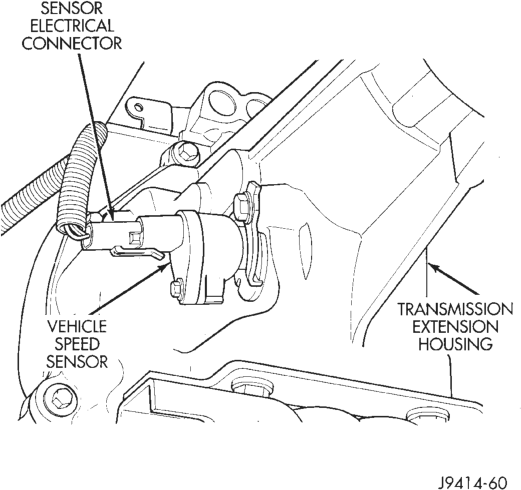
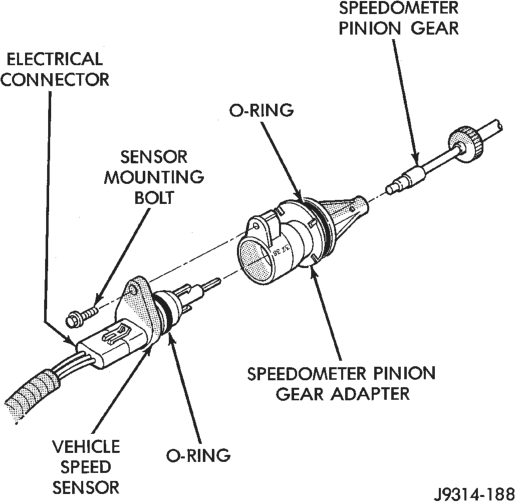
The vehicle speed sensor is located on the speedometer pinion gear adapter (Fig. 87). The pinion gear adapter is located on the extension housing of the transmission (drivers side).
REMOVAL
(1) Raise and support vehicle. (2) Disconnect the electrical connector from the sensor.
(3) Remove the sensor mounting bolt (Fig. 88). (4) Remove the sensor (pull straight out) from the speedometer pinion gear adapter (Fig. 88). Do not remove the gear adapter from the transmission.
INSTALLATION
(1) Clean the inside of speedometer pinion gear adapter before installing speed sensor.
(2) Install sensor into speedometer gear adapter and install mounting bolt. Before tightening bolt, verify speed sensor is fully seated (mounted flush) to speedometer pinion gear adapter.
(3) Tighten sensor mounting bolt to 2.2 N·m (20 in. lbs.) torque.
(4) Connect electrical connector to sensor.
SPECIFICATIONS
VECI LABEL SPECIFICATIONS
If anything differs between the specifications found on the Vehicle Emission Control Information (VECI) label and the following specifications, use specifications on VECI label. The VECI label is located in the engine compartment.
TORQUE CHART
DESCRIPTION TORQUE Air Cleaner Housing Mount.
Nuts . . . . . . . . . . . . . . . . . . . . .10 N·m (93 in. lbs.) Engine Coolant Temperature Sensor—
All Engines . . . . . . . . . . . . . . . .11 N·m (96 in. lbs.) Fuel Hose Clamps . . . . . . . . . . . . .1 N·m (10 in. lbs.) IAC Motor-To-Throttle Body Bolts .7 N·m (60 in. lbs.) Intake Manifold Air Temp. Sensor—
All Engines . . . . . . . . . . . . . . . .28 N·m (20 ft. lbs.) MAP Sensor Mounting Screws—
All Engines. . . . . . . . . . . . . . . . .3 N·m (25 in. lbs.) Oxygen Sensor—All Engines . . . .30 N·m (22 ft. lbs.) Powertrain Control Module
Mounting Screws . . . . . . . . . . . . .1 N·m (9 in. lbs.) Throttle Body Mounting Bolts—
5.2L Engine . . . . . . . . . . . . . .23 N·m (200 in. lbs.) Throttle Body Mounting Bolts—
4.0L Engine . . . . . . . . . . . . . .12 N·m (108 in. lbs.) Throttle Position Sensor Mounting
Screws—All Engines . . . . . . . . . 7 N·m (60 in. lbs.) Vehicle Speed Sensor Mounting
Bolt . . . . . . . . . . . . . . . . . . . . .2.2 N·m (20 in. lbs.)
SPECIAL TOOLS
FUEL SYSTEM
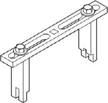
Spanner Wrench—6856
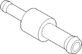
Fitting, Air Metering—6714
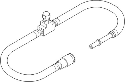
Adapters, Fuel Pressure Test—6541, 6539, 6631 or
6923
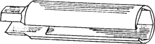
O2S (Oxygen Sensor) Remover/Installer—C-4907
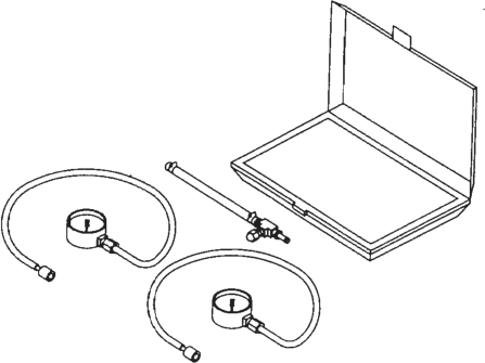
Test Kit, Fuel Pressure—5069
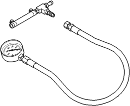
Test Kit, Fuel Pressure—C-4799-B
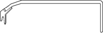
Fuel Line Removal Tool—6782