Frame and Bumpers — 1996 Jeep Grand Cherokee ZJ Service Manual
Pages 1054–1064 · 11 pages · 0 words repaired
(6) Slide the fascia off of the retainer pegs at the side of the fender attach brackets. Using a small screwdriver, pull up on locating tangs under turn signal mounting location.
(7) Remove the fascia from the vehicle
INSTALLATION
(1) Reverse removal procedure.
REAR BUMPER FASCIA
REMOVAL
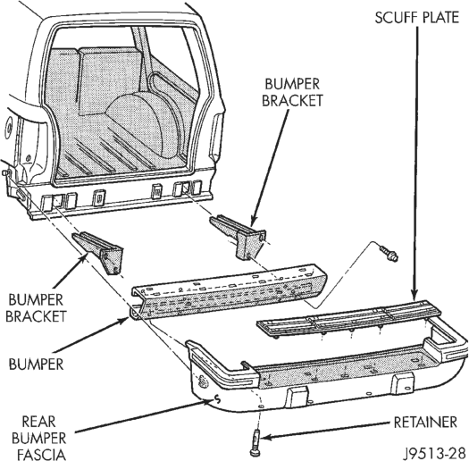
(1) Remove trailer hitch, if equipped. (2) Raise and support the rear of the vehicle. (3) Remove the upper scuff pad from fascia. (4) Remove the lower retainers from fascia (Fig. 5). (5) Remove the push-in retainers located at the rear wheel well on each side.
(6) Remove the fascia from the bumper.
INSTALLATION
(1) Reverse the removal procedure.
REAR BUMPER
REMOVAL
(1) Remove trailer hitch, if equipped. (2) Raise and support the rear of the vehicle. (3) Support the bumper. (4) Remove push-in retainers at each side rear wheel well.
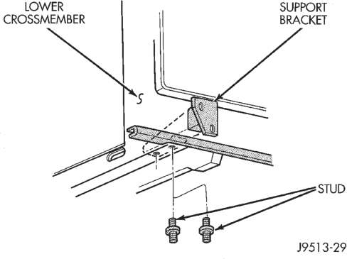
(5) Remove the bolts that attach the bumper support brackets to the rear rails (Fig. 4).
(6) Slide the bumper beam/fascia off of the retainer pegs on the side of the lower quarter panel.
(7) Remove the beam/fascia from the vehicle. (8) Remove the bumper support brackets from the bumper (Fig. 5).
(9) Remove the upper scuff pad from the bumper fascia by squeezing fasteners and pushing through slots.
(10) Remove the lower retainers from the bumper fascia.
(11) Remove the bumper fascia from the bumper.
INSTALLATION
(1) Install brackets onto bumper beam. (2) Install beam/brackets onto vehicle rails fingertight.
(3) Install fascia onto bumper assembly. (4) Check gaps and fit. Adjust as necessary. Tighten bolts to 56 N·m (41 ft-lbs).
(5) Install scuff pad. (6) If removed, install the trailer hitch.
FRAME
INDEX
GENERAL INFORMATION
GENERAL INFORMATION . . . . . . . . . . . . . . . . . . 3 REMOVAL AND INSTALLATION
FRONT SKID PLATE . . . . . . . . . . . . . . . . . . . . . . 3 FRONT TOW HOOK . . . . . . . . . . . . . . . . . . . . . . . 3 FUEL TANK SKID PLATE . . . . . . . . . . . . . . . . . . . 4
GENERAL INFORMATION
GENERAL INFORMATION
Jeep Grand Cherokee vehicles do not have a conventional frame. They are constructed as a unitized body and frame. Jeep unibodies are constructed from special high-strength steel and coated metals. This process reduces weight and provides strength to withstand the forces applied against structural members. The structural members provide a unibody that has great structural strength.
REMOVAL AND INSTALLATION
FRONT TOW HOOK
REMOVAL
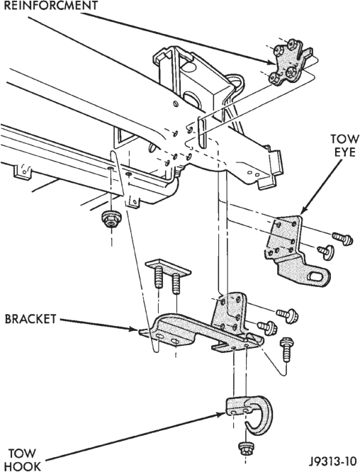
(1) Remove grille and fascia. (2) Remove the nuts and bolts that attach the tow hooks to the lower crossmember (Fig. 1).
(3) Remove the tow hooks from the lower crossmember.
INSTALLATION
(1) Attach tow hook to bracket. Tighten nuts to 95 N·m (70 ft. lbs.) torque.
(2) Position tow eye bracket at crossmember. Insert bolts thru the bracket and into the reinforcement.
(3) Position the tows hooks at the lower crossmember.
(4) Install stud plate from top of crossember, thru the crossmember and bracket. Tighten all nuts to 67 N·m (50 ft. lbs.) torque.
(5) Install fascia and grille.
page page
REAR TOW HOOK . . . . . . . . . . . . . . . . . . . . . . . . 4 TRAILER HITCH . . . . . . . . . . . . . . . . . . . . . . . . . . 5 TRANSFER CASE SKID PLATE . . . . . . . . . . . . . . 4 SPECIFICATIONS
TORQUE SPECIFICATIONS . . . . . . . . . . . . . . . . 11 VEHICLE DIMENSIONS . . . . . . . . . . . . . . . . . . . . 5
FRONT SKID PLATE
REMOVAL
(1) Position a support under skid plate.
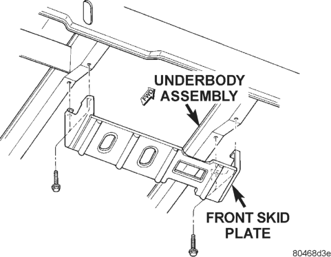
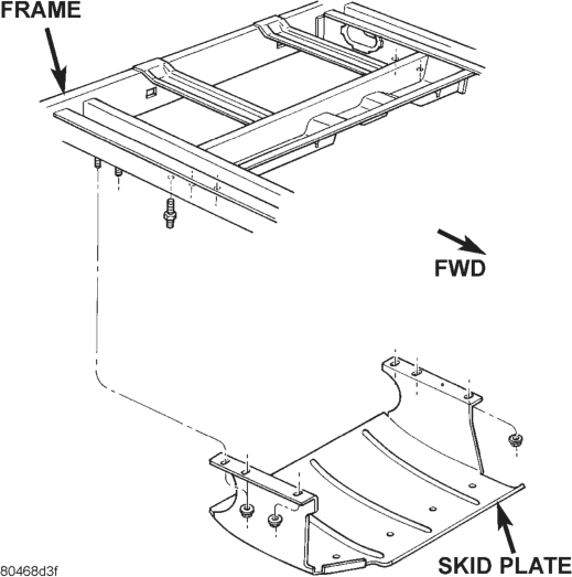
(2) Remove the bolts that attach skid plate to frame (Fig. 2).
(3) Lower the skid plate.
INSTALLATION
(1) Position the skid plate on a support. (2) Raise it into position (3) Install the bolts. Tighten the bolts to 54 N·m (40 ft. lbs.) torque.
TRANSFER CASE SKID PLATE
REMOVAL
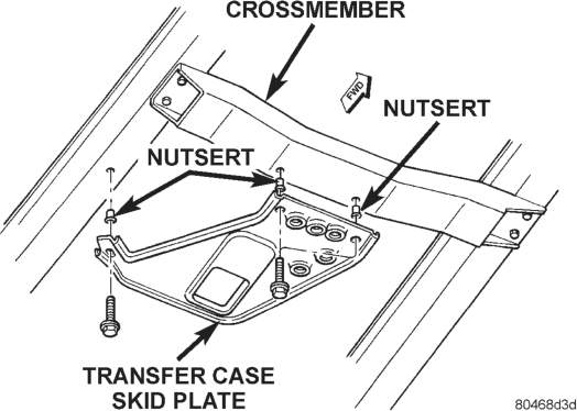
(1) Support skid plate. (2) Remove bolts that attach skid plate to transmission support crossmember and frame sill (Fig. 3).
(3) Remove support and skid plate from vehicle.
INSTALLATION
(1) Install nutserts, if removed. (2) Position and support skid plate at the frame sill and transmission support crossmember.
(3) Attach skid plate to frame sill and crossmember with the bolts. Tighten bolts to 27 N·m (20 ft. lbs) torque.
FUEL TANK SKID PLATE
REMOVAL
(1) Remove trailer hitch. (2) Position a support under the fuel tank skid plate.
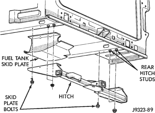
(3) Remove nuts attaching skid plate to frame rails (Fig. 4).
(4) Lower skid plate and remove support.
INSTALLATION
(1) Position skid plate on a support and raise into position.
(2) Install nuts attaching skid plate to frame rails. Tighten nuts to 74 N·m (55 ft. lbs.) torque.
(3) Remove support. (4) Install trailer hitch.
REAR TOW HOOK
REMOVAL
(1) Remove the nuts and bolts that attach the tow hook to the lower crossmember (Fig. 5).
(2) Remove the tow hook from the lower crossmember.
INSTALLATION
(1) Attach tow hook to bracket. Tighten nut to 95 N·m (70 ft. lbs.) torque.
(2) Position reinforcement plate on top of body lip.
(3) Install the bolts and nuts that attach tow hook. Tighten nut to 95 N·m (70 ft. lbs.) torque.
TRAILER HITCH
REMOVAL
(1) If necessary, remove trailer tow wire harness connector from hitch.
(2) Support hitch. (3) Remove nuts that attach the towing tube to frame sills (Fig. 6).
NOTE: Reinforcement brackets are retained on frame sills with 4 studs.
(4) Remove bolts from plate bracket and vehicle rear crossmember. Lower support and hitch.
INSTALLATION
(1) Place hitch on a lifting device. Raise, position hitch at proper location and support it.
(2) Loosely install nuts that attach towing tube to vehicle frame sills.
(3) Position plate bracket and install attaching bolts through vehicle rear crossmember.
(4) Tighten all attaching bolts/nuts. (5) Remove support and, if removed, attach trailer wire harness connector to hitch.
SPECIFICATIONS
VEHICLE DIMENSIONS
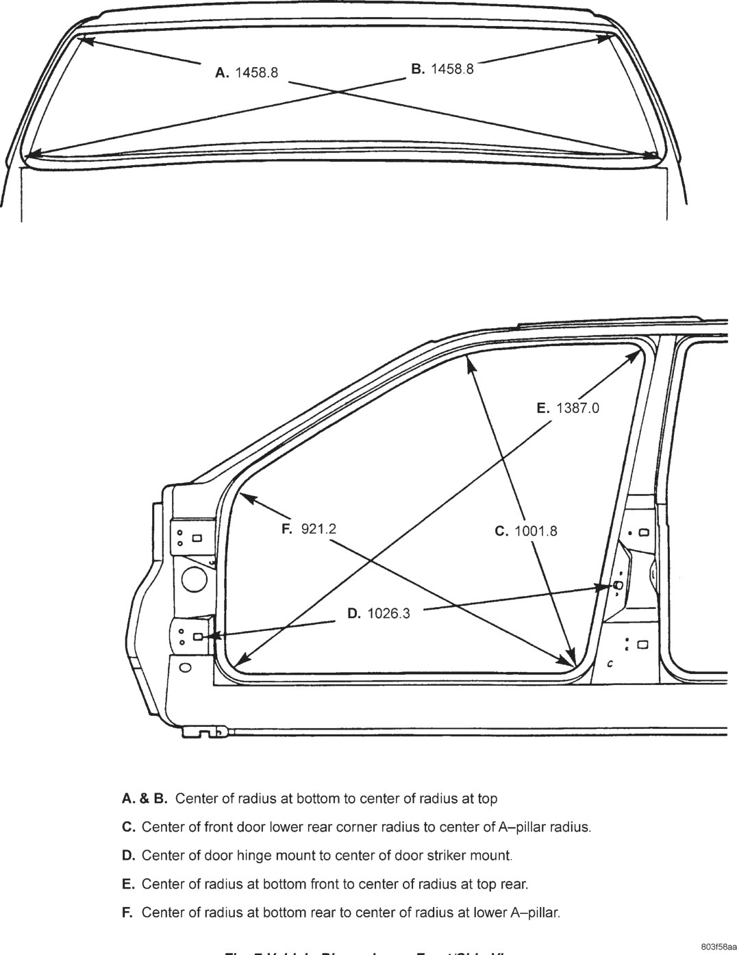
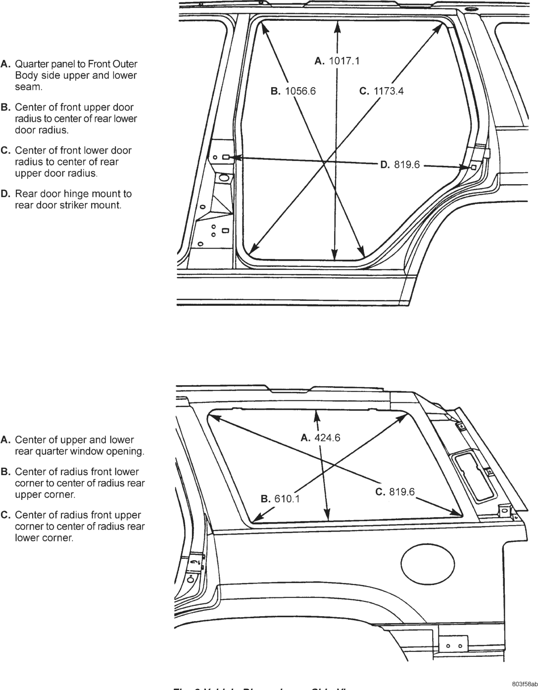
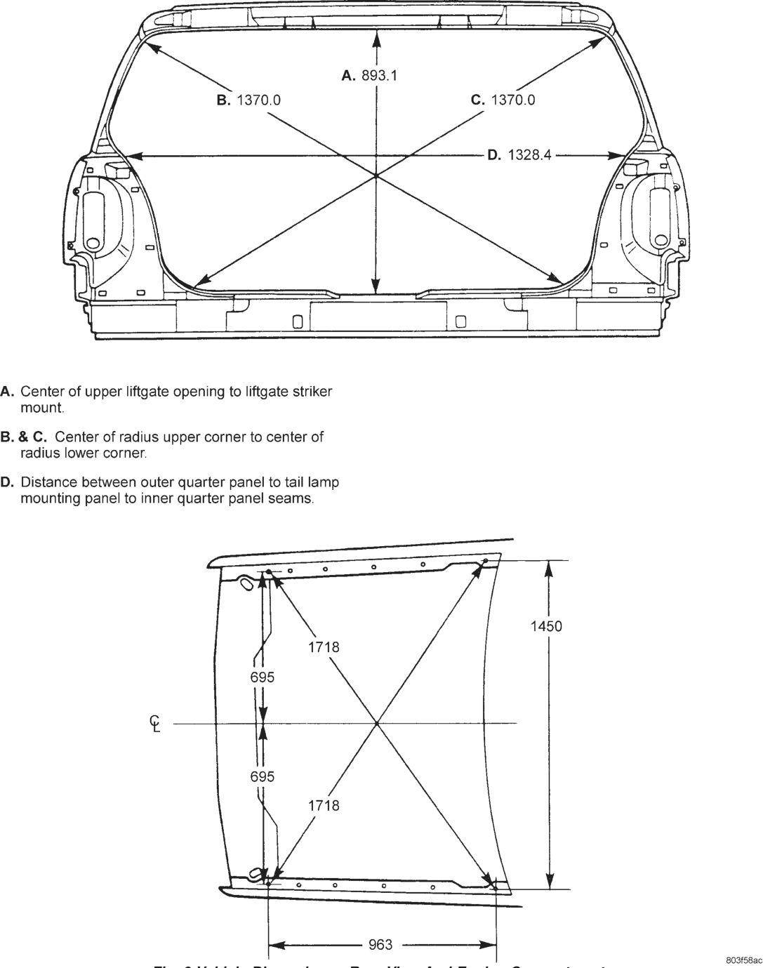
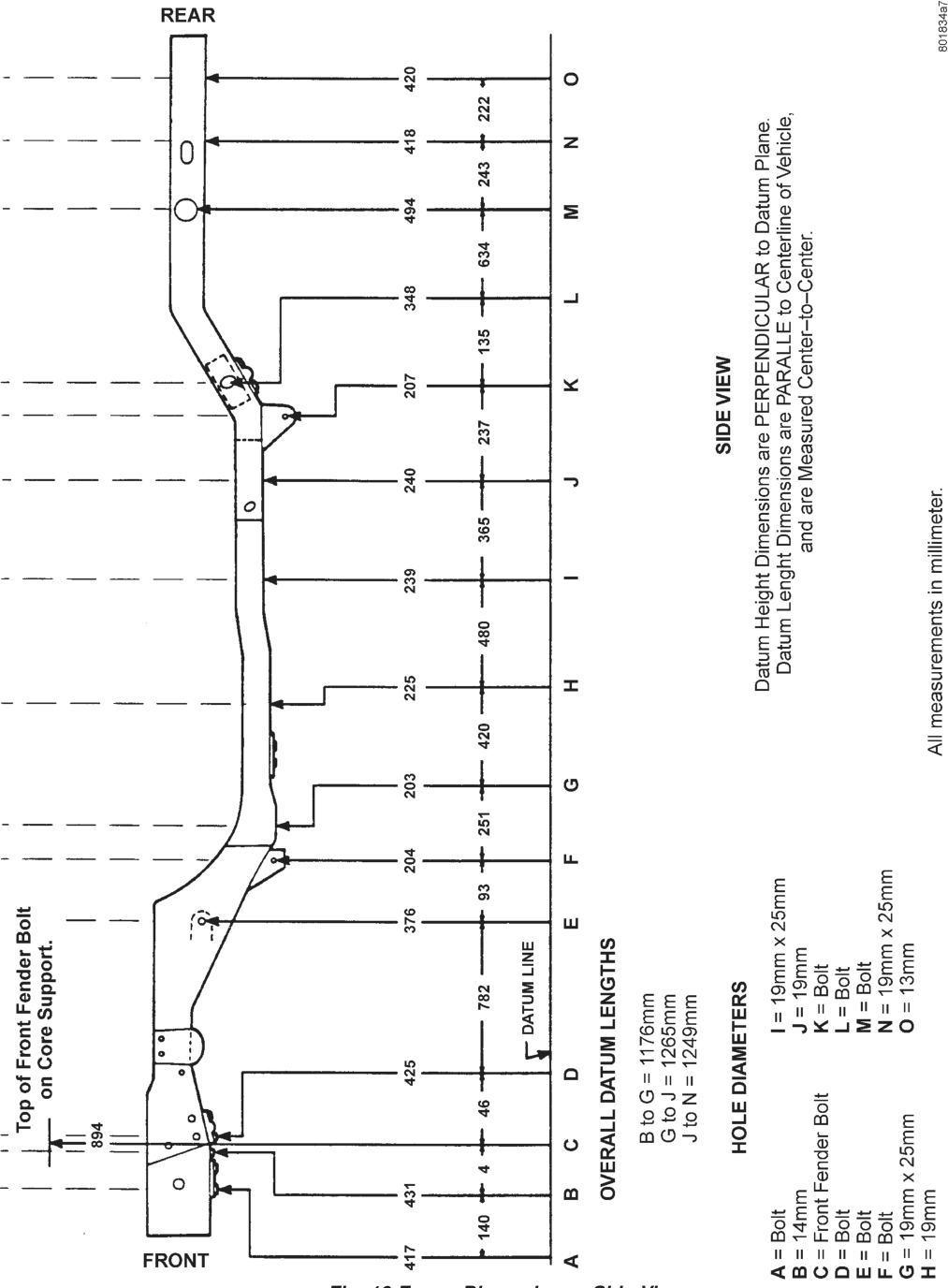
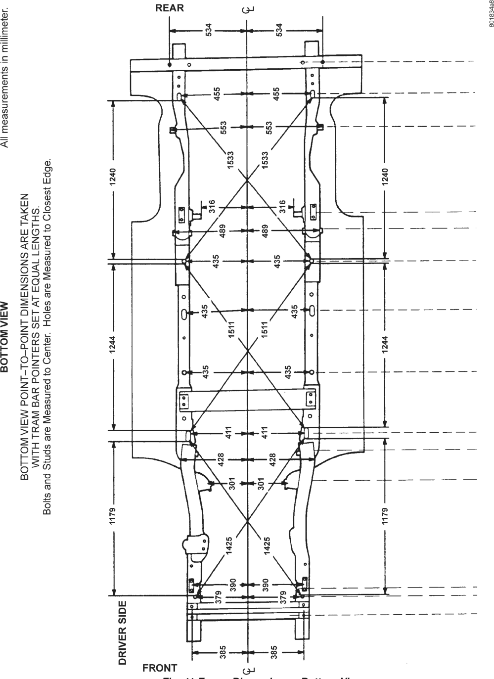
Frame dimensions are listed in metric scale. All dimensions are from center to center of Principal Locating Point (PLP), or from center to center of PLP and fastener location (Fig. 7), (Fig. 8), (Fig. 9), (Fig. 10) and (Fig. 11)
EEE = —
————————————
UO —_—
ZA E. 1387.0 |
f
[7
so | C. 1001.8 [-o|
\
|
|
234 Ww 70
N ° ee, : NS
L ribo
A. & B. Center of radius at bottom to center of radius at top
C. Center of front door lower rear corner radius to center of A—pillar radius.
D. Center of door hinge mount to center of door striker mount.
E. Center of radius at bottom front to center of radius at top rear.
F. Center of radius at bottom rear to center of radius at lower A—pillar.
_ 7 _ 803f58aa
Fig. 8 Vehicle Dimensions—Side View
\ / %
A. Quarter panel to Front Outer A. 1017.1
Body side upper and lower
seam. B. 1056.6 C. 1173.4
B. Center of front upper door
radius to center of rear lower
door radius. |
=
C. Center of front lower door - j TY
radius to center of rear = 4 D. 819.6 LL}
upper door radius. Yes] \ yy
D. Rear door hinge mount to
rear door striker mount. ° IX g
Le
oO
L}
ee SS
ak
oN
A. Center of upper and lower A. 424.6 \
rear quarter window opening. \ A\\
B. Center of radius front lower \ YS
corner to center of radius rear \
upper corner. \ B. 6101 C. 819.6
\ eo }
C. Center of radius front upper \ Oks
corner to center of radius rear
_ JO [
\—_ Fa
_ 7 803f58ab
Fig. 9 Vehicle Dimensions—Rear View And Engine Compartment
A =
SS SS
a a
—— A. 893.1
B. 1370.0 C. 1370.0
A lam
oS D. 1328.4 <=>
kee 7 Ps
DL S) SAN
A. Center of upper liftgate opening to liftgate striker
mount.
B. & C. Center of radius upper corner to center of
radius lower corner.
D. Distance between outer quarter panel to tail lamp
mounting panel to inner quarter panel seams.
&
9
1450
1718
695
¢
695
1718
I
963
_ 7 7 7 a 803f58ac
TORQUE SPECIFICATIONS
DESCRIPTION TORQUE Front Tow Hook Nut . . . . . . . . . .100 N·m (74 ft. lbs.) Front Skid Plate Bolt . . . . . . . . . .54 N·m (40 ft. lbs.) Fuel Tank Skid Plate Nuts . . . . . .74 N·m (55 ft. lbs.) Fuel Tank Skid Plate Mtg Studs.108 N·m (80 ft. lbs.) Rear Bumper Bolt. . . . . . . . . . . . .56 N·m (41 ft. lbs.) Rear Tow Hook Nut . . . . . . . . . .100 N·m (74 ft. lbs.) Trailer Hitch Nuts/Bolts . . . . . . . .74 N·m (55 ft. lbs.) Transfer Case Skid Plate Bolts . . .27 N·m (20 ft. lbs.)