Engine — part 1 of 2 — 1996 Jeep Grand Cherokee ZJ Service Manual
← Contents 1 2
Pages 958–1017 · 60 pages · 15 words repaired
circled. For corner sealing, a 3 or 6 mm (1/8 or 1/4 inch) drop is placed in the center of the gasket contact area. Uncured sealant may be removed with a shop towel. Components should be torqued in place while the sealant is still wet to the touch (within ten minutes). The use of a locating dowel is recommended during assembly to prevent smearing the material off location.
Mopart Gasket Maker should be applied sparingly to one gasket surface. The sealant diameter should be 1.00 mm (0.04 inch) or less. Be certain the material surrounds each mounting hole. Excess material can be easily wiped off. Components should be torqued in place within 15 minutes. The use of a locating dowel is recommended during assembly to prevent smearing the material off location.
ENGINE PERFORMANCE
To provide best vehicle performance and lowest vehicle emissions, it is most important that the tune-up be done accurately. Use the specifications listed on the Vehicle Emission Control Information label found on the engine compartment hood.
(1) Test battery specific gravity. Add water, if necessary. Clean and tighten battery connections.
(2) Test cranking amperage draw (refer to Group 8B, Battery/Starter for the proper procedure). (3) Tighten the intake manifold bolts (refer to Group 11, Exhaust System and Intake Manifold for the proper specifications).
(4) Perform cylinder compression test:
CAUTION: DO NOT overspeed the engine.
(a) Check engine oil level and add oil, if necessary.
(b) Drive the vehicle until engine reaches normal operating temperature.
(c) Select a route free from traffic and other forms of congestion, observe all traffic laws and briskly accelerate through the gears several times. The higher engine speed may help clean out valve seat deposits which can prevent accurate compression readings.
(d) Remove all spark plugs from engine. As spark plugs are being removed, check electrodes for abnormal firing indicators - fouled, hot, oily, etc. Record cylinder number of spark plug for future reference.
(e) Disconnect coil wire from distributor and secure to good ground to prevent a spark from starting a fire.
(f) Be sure throttle blades are fully open during the compression check.
(g) Insert compression gage adaptor into the No.1 spark plug hole. Crank engine until maximum pressure is reached on gauge. Record this pressure as No.1 cylinder pressure.
(h) Repeat for all remaining cylinders. (i) Compression should not be less than 689 kPa (100 psi) and not vary more than 172 kPa (25 psi) from cylinder to cylinder.
(j) If cylinder(s) have abnormally low compression pressures, repeat procedure.
(k) If the same cylinder(s) repeat an abnormally low reading, it could indicate the existence of a problem in the cylinder.
NOTE: The recommended compression pressures are to be used only as a guide to diagnosing engine problems. An engine should NOT be disassembled to determine the cause of low compression unless some malfunction is present.
(5) Clean or replace spark plugs as necessary. Adjust gap (refer to Group 8D, Ignition System for gap adjustment and torque).
(6) Test resistance of spark plug cables (refer to Group 8D, Ignition System).
(7) Inspect the primary wire. Test coil output voltage, primary and secondary resistance. Replace parts as necessary (refer to Group 8D, Ignition System and make necessary adjustment).
(8) Set ignition timing to specifications (refer to Specification Label on engine compartment hood).
(9) Perform a combustion analysis. (10) Test fuel pump for pressure (refer to Group 14, Fuel System for the proper specifications). (11) Inspect air filter element (refer to Group 0, Lubrication and Maintenance for the proper procedure).
(12) Inspect crankcase ventilation system (refer to Group 0, Lubrication and Maintenance for the proper procedure).
(13) For emission controls refer to Group 25, Emission Controls System for service procedures.
(14) Inspect and adjust accessory belt drives (refer to Group 7, Cooling System for the proper adjustments).
(15) Road test vehicle as a final test.
HONING CYLINDER BORES
Before honing, stuff plenty of clean shop towels under the bores and over the crankshaft to keep abrasive materials from entering the crankshaft area.
(1) Used carefully, the Cylinder Bore Sizing Hone C-823 equipped with 220 grit stones, is the best tool for this job. In addition to deglazing, it will reduce taper and out-of-round as well as removing light scuffing, scoring or scratches. Usually a few strokes will clean up a bore and maintain the required limits.
CAUTION: DO NOT use rigid type hones to remove cylinder wall glaze.
(2) Deglazing of the cylinder walls may be done if the cylinder bore is straight and round. Use a cylinder surfacing hone, Honing Tool C-3501, equipped with 280 grit stones (C-3501-3810). 20-60 strokes, depending on the bore condition, will be sufficient to provide a satisfactory surface. Using honing oil C-3501-3880 or a light honing oil available from major oil distributors.
CAUTION: DO NOT use engine or transmission oil, mineral spirits or kerosene.
(3) Honing should be done by moving the hone up and down fast enough to get a crosshatch pattern. The hone marks should INTERSECT at 50° to 60° for proper seating of rings (Fig. 1).
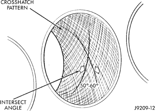
(4) A controlled hone motor speed between 200 and 300 RPM is necessary to obtain the proper crosshatch angle. The number of up and down strokes per minute can be regulated to get the desired 50° to 60° angle. Faster up and down strokes increase the crosshatch angle.
(5) After honing, it is necessary that the block be cleaned to remove all traces of abrasive. Use a brush to wash parts with a solution of hot water and detergent. Dry parts thoroughly. Use a clean, white, lintfree cloth to check that the bore is clean. Oil the bores after cleaning to prevent rusting.
MEASURING WITH PLASTIGAGE
CRANKSHAFT MAIN BEARING CLEARANCE
Engine crankshaft bearing clearances can be determined by use of Plastigage, or equivalent. The following is the recommended procedures for the use of Plastigage:
(1) Remove oil film from surface to be checked. Plastigage is soluble in oil.
(2) The total clearance of the main bearings can only be determined by removing the weight of the crankshaft. This can be accomplished by either of two methods:
METHOD - 1 (PREFERRED)
Shim the bearings adjacent to the bearing to be checked. This will remove the clearance between upper bearing shell and the crankshaft. Place a minimum of 0.254 mm (0.010 inch) shim between the bearing shell and the adjacent bearing cap. Tighten the bolts to 18 N·m (13 ft. lbs.) torque.
• ALL ENGINES—When checking No.1 main bearing; shim No.2 main bearing.
• ALL ENGINES—When checking No.2 main bearing; shim No.1 and No.3 main bearing.
• ALL ENGINES—When checking No.3 main bearing; shim No.2 and No.4 main bearing.
• ALL ENGINES—When checking No.4 main bearing; shim No.3 and No.5 main bearing.
• 5.2L ENGINE—When checking No.5 main bearing; shim No.4 main bearing.
• 4.0L ENGINE—When checking No.5 main bearing; shim No.4 and No.6 main bearing.
• 4.0L ENGINE—When checking No.6 main bearing; shim No.5 and No.7 main bearing.
• 4.0L ENGINE—When checking No.7 main bearing; shim No.6 main bearing.
NOTE: Remove all shims before assembling engine.
METHOD - 2 (ALTERNATIVE)
The weight of the crankshaft is supported by a jack under the counterweight adjacent to the bearing being checked.
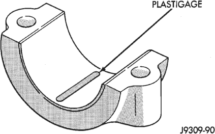
(1) Place a piece of Plastigage across the entire width of the bearing cap shell (Fig. 2). Position the Plastigage approximately 6.35 mm (1/4 inch) off center and away from the oil holes. In addition, suspect areas can be checked by placing the Plastigage in that area. Tighten the bearing cap bolts of the bearing being checked to 108 N·m (80 ft. lbs.) torque (4.0L Engine). Tighten the bearing cap bolts of the bearing being checked to 115 N·m (85 ft. lbs.) torque (5.2L Engine). DO NOT rotate the crankshaft or the Plastigage may be smeared, giving inaccurate results.
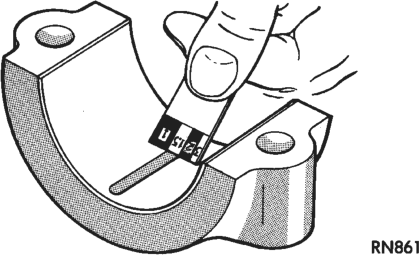
(2) Remove the bearing cap and compare the width of the flattened Plastigage with the scale provided on the package (Fig. 3). Plastigage generally comes in 2 scales (one scale is in inches and the other is a metric scale). Locate the band closest to the same width. This band shows the amount of clearance. Differ-
ences in readings between the ends indicate the amount of taper present. Record all readings taken (refer to Engine Specifications).
(3) Plastigage is available in a variety of clearance ranges. The 0.025-0.076 mm (0.001-0.003 inch) range is usually the most appropriate for checking engine bearing clearances.
CONNECTING ROD BEARING CLEARANCE
Engine connecting rod bearing clearances can be determined by use of Plastigage, or equivalent. The following is the recommended procedures for the use of Plastigage:
(1) Remove oil film from surface to be checked. Plastigage is soluble in oil.
(2) Place a piece of Plastigage across the entire width of the bearing cap shell (Fig. 2). Position the Plastigage approximately 6.35 mm (1/4 inch) off center and away from the oil holes. In addition, suspect areas can be checked by placing the Plastigage in the suspect area.
(3) The crankshaft must be turned until the connecting rod to be checked starts moving toward the top of the engine. Only then should the rod cap with Plastigage in place be assembled. Tighten the 4.0L rod cap nut to 45 N·m (33 ft. lbs.) torque. Tighten the 5.2L rod cap nut to 61 N·m (45 ft. lbs.) torque. DO NOT rotate the crankshaft or the Plastigage may be smeared, giving inaccurate results.
(4) Remove the bearing cap and compare the width of the flattened Plastigage with the scale provided on the package (Fig. 2). Plastigage generally comes in 2 scales (one scale is in inches and the other is a metric scale). Locate the band closest to the same width. This band shows the amount of clearance. Differences in readings between the ends indicate the amount of taper present. Record all readings taken (refer to Engine Specifications).
(5) Plastigage is available in a variety of clearance ranges. The 0.025-0.076 mm (0.001-0.003 inch) range is usually the most appropriate for checking engine bearing clearances.
REPAIR DAMAGED OR WORN THREADS
Damaged or worn threads can be repaired. Essentially, this repair consists of:
• Drilling out worn or damaged threads. • Tapping the hole with a special Heli-Coil Tap, or equivalent.
• Installing an insert into the tapped hole to bring the hole back to its original thread size.
CAUTION: Be sure that the tapped holes maintain the original center line.
Heli-Coil tools and inserts are readily available from automotive parts jobbers.
SERVICE ENGINE ASSEMBLY (SHORT BLOCK)
A service replacement engine assembly (short block) may be installed whenever the original cylinder block is defective or damaged beyond repair. It consists of the cylinder block, crankshaft, piston and rod assemblies. If needed, the camshaft must be procured separately and installed before the engine is installed in the vehicle.
A short block is identified with the letter “S” stamped on the same machined surface where the build date code is stamped for complete engine assemblies.
Installation includes the transfer of components from the defective or damaged original engine. Follow the appropriate procedures for cleaning, inspection and torque tightening.
HYDROSTATIC LOCK
When an engine is suspected of hydrostatic lock (regardless of what caused the problem), follow the steps below.
(1) Perform the Fuel Pressure Release Procedure (refer to Group 14, Fuel System).
(2) Disconnect the negative cable from the battery. (3) Inspect air cleaner, induction system and intake manifold to ensure system is dry and clear of foreign material.
(4) Place a shop towel around the spark plugs to catch any fluid that may possibly be under pressure in the cylinder head. Remove the plugs from the engine.
CAUTION: DO NOT use the starter motor to rotate the crankshaft. Severe damage could occur.
(5) With all spark plugs removed, rotate the crankshaft using a breaker bar and socket.
(6) Identify the fluid in the cylinders (i.e. coolant, fuel, oil, etc.).
(7) Make sure all fluid has been removed from the cylinders.
(8) Repair engine or components as necessary to prevent this problem from occurring again.
(9) Squirt engine oil into the cylinders to lubricate the walls. This will prevent damage on restart.
(10) Install new spark plugs. Tighten the 4.0L engine spark plugs to 37 N·m (27 ft. lbs.) torque. Tighten the 5.2L engine spark plugs to 41 N·m (30 ft. lbs.) torque.
(11) Drain engine oil. Remove and discard the oil filter.
(12) Install the drain plug. Tighten the plug to 34 N·m (25 ft. lbs.) torque.
(13) Install a new oil filter. (14) Fill engine crankcase with the specified amount and grade of oil.
(15) Connect the negative cable to the battery. (16) Start the engine and check for any leaks.
ENGINE OIL
WARNING: NEW OR USED ENGINE OIL CAN BE IRRITATING TO THE SKIN. AVOID PROLONGED OR REPEATED SKIN CONTACT WITH ENGINE OIL. CONTAMINANTS IN USED ENGINE OIL, CAUSED BY INTERNAL COMBUSTION, CAN BE HAZARDOUS TO YOUR HEALTH. THOROUGHLY WASH EXPOSED SKIN WITH SOAP AND WATER. DO NOT WASH SKIN WITH GASOLINE, DIESEL FUEL, THINNER, OR SOLVENTS, HEALTH PROBLEMS CAN RESULT. DO NOT POLLUTE, DISPOSE OF USED ENGINE OIL PROPERLY.
ENGINE OIL SPECIFICATION
CAUTION: Do not use non-detergent or straight mineral oil when adding or changing crankcase lubricant. Engine failure can result.
API SERVICE GRADE CERTIFIED
Use an engine oil that is API Service Grade Certified or an oil that conforms to the API Service Grade
SH or SH/CD. MOPAR provides engine oils that conform to all of these service grades.
SAE VISCOSITY
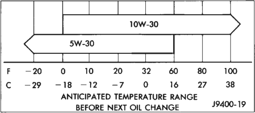
An SAE viscosity grade is used to specify the viscosity of engine oil. SAE 30 specifies a single viscosity engine oil. Engine oils also have multiple viscosities. These are specified with a dual SAE viscosity grade which indicates the cold-to-hot temperature viscosity range. Select an engine oil that is best suited to your particular temperature range and variation (Fig. 4).
ENERGY CONSERVING OIL
An Energy Conserving type oil is recommended for gasoline engines. They are designated as either ENERGY CONSERVING or ENERGY CONSERV- ING II.
CONTAINER IDENTIFICATION
Standard engine oil identification notations have been adopted to aid in the proper selection of engine oil. The identifying notations are located on the label of engine oil plastic bottles and the top of engine oil cans (Fig. 5).

ENGINE OIL ADDITIVES
In some instances, such as infrequent operation, short trip driving, and during break-in after a major overhaul, addition of special materials containing anti-rust and anti-scuff additives are beneficial. A suitable product for this purpose is MOPAR Engine Oil Supplement.
OIL LEVEL INDICATOR (DIPSTICK)
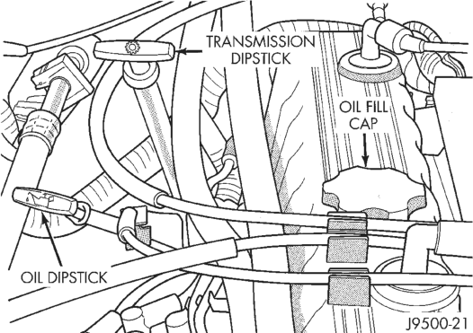
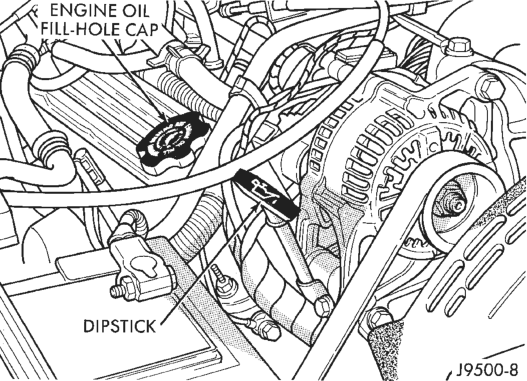
The engine oil level indicator is located at the right rear of engine on 4.0L engines (Fig. 6) and the right front of the engine on 5.2L engines (Fig. 7).
CRANKCASE OIL LEVEL INSPECTION
CAUTION: Do not overfill crankcase with engine oil, oil foaming and oil pressure loss can result.
Inspect engine oil level approximately every 800 kilometers (500 miles). Unless the engine has exhibited loss of oil pressure, run the engine for about five minutes before checking oil level. Checking engine oil level on a cold engine is not accurate.
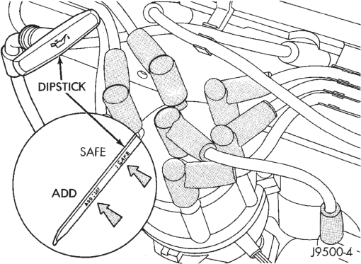
To ensure proper lubrication of an engine, the engine oil must be maintained at an acceptable level. The acceptable levels are indicated between the ADD and SAFE marks on the engine oil dipstick (Fig. 8).
(1) Position vehicle on level surface. (2) With engine OFF, allow approximately ten minutes for oil to settle to bottom of crankcase, remove engine oil dipstick.
(3) Wipe dipstick clean. (4) Install dipstick and verify it is seated in the tube.
(5) Remove dipstick, with handle held above the tip, take oil level reading (Fig. 8).
(6) Add oil only if level is below the ADD mark on dipstick.
ENGINE OIL CHANGE
Change engine oil at mileage and time intervals described in Maintenance Schedules.
Run engine until achieving normal operating temperature.
(1) Position the vehicle on a level surface and turn engine off.
(2) Hoist and support vehicle on safety stands. (3) Remove oil fill cap. (4) Place a suitable drain pan under crankcase drain.
(5) Remove drain plug from crankcase and allow oil to drain into pan. Inspect drain plug threads for stretching or other damage. Replace drain plug if damaged.
(6) Install drain plug in crankcase. (7) Lower vehicle and fill crankcase with specified type and amount of engine oil described in this section.
(8) Install oil fill cap. (9) Start engine and inspect for leaks. (10) Stop engine and inspect oil level.
ENGINE OIL FILTER CHANGE
FILTER SPECIFICATION
All engines are equipped with a high quality fullflow, disposable type oil filter. Chrysler Corporation recommends a Mopar or equivalent oil filter be used.
OIL FILTER REMOVAL
(1) Position a drain pan under the oil filter. (2) Using a suitable oil filter wrench loosen filter. (3) Rotate the oil filter counterclockwise (Fig. 9) to remove it from the cylinder block oil filter boss.
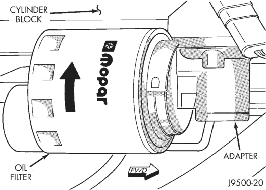
(4) When filter separates from adapter nipple, tip gasket end upward to minimize oil spill. Remove filter from vehicle.
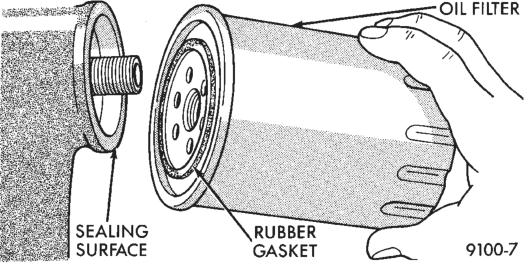
(5) With a wiping cloth, clean the gasket sealing surface (Fig. 10) of oil and grime.
OIL FILTER INSTALLATION
(1) Lightly lubricate oil filter gasket with engine oil or chassis grease.
(2) Thread filter onto adapter nipple. When gasket makes contact with sealing surface, (Fig. 10) hand tighten filter one full turn, do not over tighten.
(3) Add oil, verify crankcase oil level and start engine. Inspect for oil leaks.
USED ENGINE OIL DISPOSAL
Care should be exercised when disposing used engine oil after it has been drained from a vehicle engine. Refer to the WARNING at beginning of this section.
ENGINE DIAGNOSIS
INDEX
DIAGNOSIS AND TESTING
CYLINDER COMBUSTION PRESSURE
LEAKAGE TEST . . . . . . . . . . . . . . . . . . . . . . . . 9 CYLINDER COMPRESSION PRESSURE TEST . . 8 ENGINE CYLINDER HEAD GASKET FAILURE
DIAGNOSIS . . . . . . . . . . . . . . . . . . . . . . . . . . . 8 ENGINE OIL PRESSURE . . . . . . . . . . . . . . . . . . 11 ENGINE—LUBRICATION . . . . . . . . . . . . . . . . . . 14
DIAGNOSIS AND TESTING
GENERAL INFORMATION
Engine diagnosis is helpful in determining the causes of malfunctions not detected and remedied by routine tune-ups.
These malfunctions may be classified as either performance (e.g., engine idles rough and stalls) or mechanical (e.g., a strange noise).
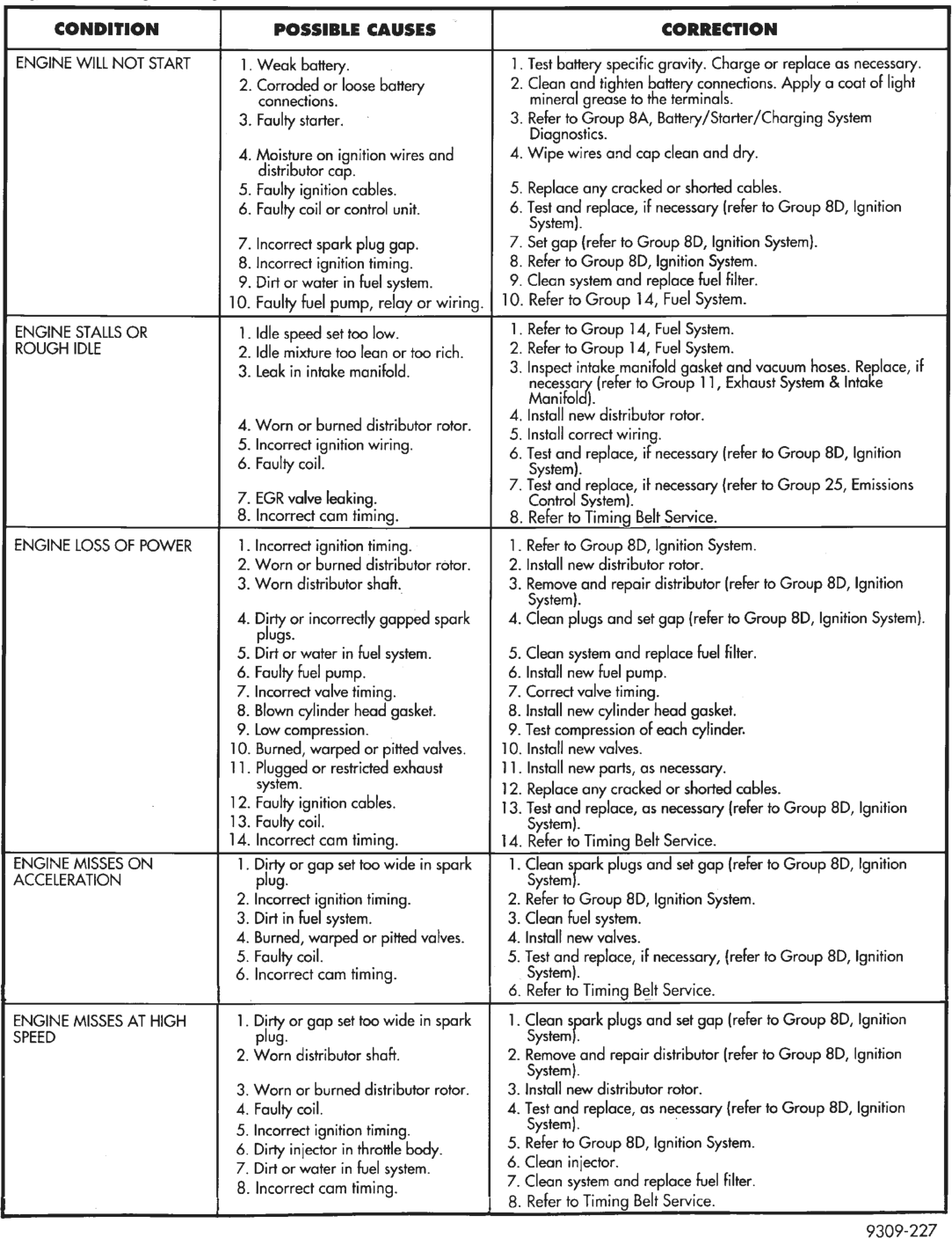
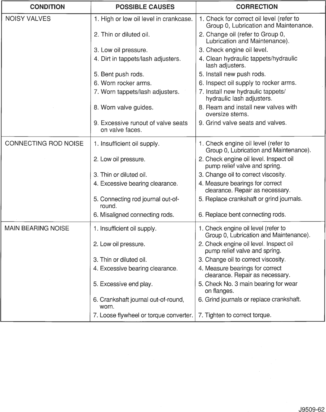
Refer to the Service Diagnosis—Performance chart and the Service Diagnosis—Mechanical chart for possible causes and corrections of malfunctions. Refer to Group 14, Fuel System for the fuel system diagnosis.
Additional tests and diagnostic procedures may be necessary for specific engine malfunctions that can not be isolated with the Service Diagnosis charts. Information concerning additional tests and diagnosis is provided within the following diagnosis:
• Cylinder Compression Pressure Test. • Cylinder Combustion Pressure Leakage Test. • Engine Cylinder Head Gasket Failure Diagnosis. • Intake Manifold Leakage Diagnosis.
INTAKE MANIFOLD LEAKAGE DIAGNOSIS
An intake manifold air leak is characterized by lower than normal manifold vacuum. Also, one or more cylinders may not be functioning.
WARNING: USE EXTREME CAUTION WHEN THE ENGINE IS OPERATING. DO NOT STAND IN A DIRECT LINE WITH THE FAN. DO NOT PUT YOUR HANDS NEAR THE PULLEYS, BELTS OR THE FAN. DO NOT WEAR LOOSE CLOTHING.
(1) Start the engine. (2) Spray a small stream of water at the suspected leak area.
(3) If a change in RPM is observed the area of the suspected leak has been found.
(4) Repair as required.
page page
ENGINE—MECHANICAL . . . . . . . . . . . . . . . . . . 13 ENGINE—PERFORMANCE . . . . . . . . . . . . . . . . 12 GENERAL INFORMATION . . . . . . . . . . . . . . . . . . 8 HYDRAULIC TAPPETS . . . . . . . . . . . . . . . . . . . . 10 INSPECTION (ENGINE OIL LEAKS IN
GENERAL) . . . . . . . . . . . . . . . . . . . . . . . . . . . . 9 INTAKE MANIFOLD LEAKAGE DIAGNOSIS . . . . . 8
CYLINDER COMPRESSION PRESSURE TEST
The results of a cylinder compression pressure test can be utilized to diagnose several engine malfunctions.
Ensure the battery is completely charged and the engine starter motor is in good operating condition. Otherwise the indicated compression pressures may not be valid for diagnosis purposes.
(1) Clean the spark plug recesses with compressed air.
(2) Remove the spark plugs. (3) Secure the throttle in the wide-open position. (4) Disconnect the ignition coil. (5) Insert a compression pressure gauge and rotate the engine with the engine starter motor for three revolutions.
(6) Record the compression pressure on the 3rd revolution. Continue the test for the remaining cylinders.
Refer to Engine Specifications for the correct engine compression pressures.
ENGINE CYLINDER HEAD GASKET FAILURE DIAGNOSIS
A leaking engine cylinder head gasket usually results in loss of power, loss of coolant and engine misfiring.
An engine cylinder head gasket leak can be located between adjacent cylinders or between a cylinder and the adjacent water jacket.
• An engine cylinder head gasket leaking between adjacent cylinders is indicated by a loss of power and/or engine misfire.
• An engine cylinder head gasket leaking between a cylinder and an adjacent water jacket is indicated by coolant foaming or overheating and loss of coolant.
CYLINDER-TO-CYLINDER LEAKAGE TEST
To determine if an engine cylinder head gasket is leaking between adjacent cylinders; follow the procedures outlined in Cylinder Compression Pressure Test. An engine cylinder head gasket leaking between adjacent cylinders will result in approximately a 50-70% reduction in compression pressure.
CYLINDER-TO-WATER JACKET LEAKAGE TEST
WARNING: USE EXTREME CAUTION WHEN THE ENGINE IS OPERATING. DO NOT STAND IN A DIRECT LINE WITH THE FAN. DO NOT PUT YOUR HANDS NEAR THE PULLEYS, BELTS OR THE FAN. DO NOT WEAR LOOSE CLOTHING.
Remove the radiator cap. Start the engine and allow it to warm up until the engine thermostat opens.
If a large combustion/compression pressure leak exists, bubbles will be visible in the coolant.
If bubbles are not visible, install a radiator pressure tester and pressurize the coolant system.
If a cylinder is leaking combustion pressure into the water jacket, the tester pointer will pulsate with every combustion stroke of the cylinder.
CYLINDER COMBUSTION PRESSURE LEAKAGE TEST
The combustion pressure leakage test provides an accurate means for determining engine condition.
Combustion pressure leakage testing will detect: • Exhaust and intake valve leaks (improper seating).
• Leaks between adjacent cylinders or into water jacket.
CARBURETOR/THROTTLE necessary.
Body :
AIR ESCAPES Exhaust valve not seated properly. Inspect valve.Reface or replace, if
THROUGH TAILPIPE necessary.
AIR ESCAPES Head gasket leaks or crack in cylinder Remove cylinder head and inspect.
THROUGH RADIATOR block. Replace, if necessary.
MORE THAN 50% LEAKAGE Head gasket leaks or crack in cylinder Remove cylinder head and inspect.
FROM ADJACENT CYLINDERS block or head between adjacent cylinders. Replace gasket or head, if necessary.
MORE THAN 25% LEAKAGE Stuck or broken piston ring(s); cracked Inspect for broken ring\s) or piston.
AND AIR ESCAPES THROUGH piston; worn rings and/or cylinder wall. Measure ring gap and cylinder diameter,
OIL FILLER CAP OPENING ONLY taper, and out-of-round. Replace affected
part, if necessary.
J8909-78
• Any causes for combustion/compression pressure loss.
(1) Check the coolant level and fill as required. DO NOT install the radiator cap.
(2) Start and operate the engine until it attains normal operating temperature, then turn the engine OFF.
(3) Remove the spark plugs. (4) Remove the oil filler cap. (5) Remove the air cleaner. (6) Calibrate the tester according to the manufacturer’s instructions. The shop air source for testing should maintain 483 kPa (70 psi) minimum, 1 379 kPa (200 psi) maximum and 552 kPa (80 psi) recommended.
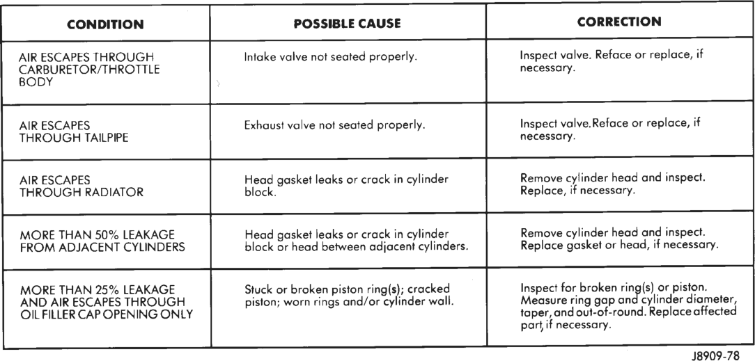
(7) Perform the test procedures on each cylinder according to the tester manufacturer’s instructions. While testing, listen for pressurized air escaping through the throttle body, tailpipe and oil filler cap opening. Check for bubbles in the radiator coolant.
All gauge pressure indications should be equal, with no more than 25% leakage.
FOR EXAMPLE: At 552 kPa (80 psi) input pressure, a minimum of 414 kPa (60 psi) should be maintained in the cylinder.
Refer to the Cylinder Combustion Pressure Leakage Test Diagnosis chart.
INSPECTION (ENGINE OIL LEAKS IN GENERAL)
Begin with a through visual inspection of the engine, particularly at the area of the suspected leak. If an oil leak source is not readily identifiable, the following steps should be followed:
(1) Do not clean or degrease the engine at this time because some solvents may cause rubber to swell, temporarily stopping the leak.
(2) Add an oil soluble dye (use as recommended by manufacturer). Start the engine and let idle for approximately 15 minutes. Check the oil dipstick to make sure the dye is thoroughly mixed as indicated with a bright yellow color under a black light.
(3) Using a black light, inspect the entire engine for fluorescent dye, particularly at the suspected area of oil leak. If the oil leak is found and identified, repair per service manual instructions.
(4) If dye is not observed, drive the vehicle at various speeds for approximately 24km (15 miles), and repeat inspection.
(5) If the oil leak source is not positively identified at this time, proceed with the air leak detection test method.
Air Leak Detection Test Method
(1) Disconnect the breather cap to air cleaner hose at the breather cap end. Cap or plug breather cap nipple.
(2) Remove the PCV valve from the cylinder head cover. Cap or plug the PCV valve grommet.
(3) Attach an air hose with pressure gauge and regulator to the dipstick tube.
CAUTION: Do not subject the engine assembly to more than 20.6 kpa (3 PSI) of test pressure.
(4) Gradually apply air pressure from 1 psi to 2.5 psi maximum while applying soapy water at the suspected source. Adjust the regulator to the suitable test pressure that provide the best bubbles which will pinpoint the leak source. If the oil leak is detected and identified, repair per service manual procedures.
(5) If the leakage occurs at the rear oil seal area, refer to the section, Inspection for Rear Seal Area Leak.
(6) If no leaks are detected, turn off the air supply and remove the air hose and all plugs and caps. Install the PCV valve and breather cap hose.
(7) Clean the oil off the suspect oil leak area using a suitable solvent. Drive the vehicle at various speeds approximately 24 km (15 miles). Inspect the engine for signs of an oil leak by using a black light.
INSPECTION FOR REAR SEAL AREA LEAKS
Since it is sometimes difficult to determine the source of an oil leak in the rear seal area of the engine, a more involved inspection is necessary. The following steps should be followed to help pinpoint the source of the leak.
If the leakage occurs at the crankshaft rear oil seal area:
(1) Disconnect the battery. (2) Raise the vehicle. (3) Remove torque converter or clutch housing cover and inspect rear of block for evidence of oil. Use a black light to check for the oil leak:
(a) Circular spray pattern generally indicates seal leakage or crankshaft damage.
(b) Where leakage tends to run straight down, possible causes are a porous block, distributor seal, camshaft bore cup plugs oil galley pipe plugs, oil filter runoff, and main bearing cap to cylinder block mating surfaces. (4) If no leaks are detected, pressurize the crankcase as outlined in the, Inspection (Engine oil Leaks in general)
CAUTION: Do not exceed 20.6 kPa (3 psi).
(5) If the leak is not detected, very slowly turn the crankshaft and watch for leakage. If a leak is detected between the crankshaft and seal while slowly turning the crankshaft, it is possible the crankshaft seal surface is damaged. The seal area on the crankshaft could have minor nicks or scratches that can be polished out with emery cloth.
CAUTION: Use extreme caution when crankshaft polishing is necessary to remove minor nicks and scratches. The crankshaft seal flange is especially machined to complement the function of the rear oil seal.
(6) For bubbles that remain steady with shaft rotation, no further inspection can be done until disassembled.
HYDRAULIC TAPPETS
Before disassembling any part of the engine to correct tappet noise, check the oil pressure. If vehicle has no oil pressure gauge, install a reliable gauge at the pressure sending-unit. The pressure should be between 207-552 kPa (30-80 psi) at 3,000 RPM.
Check the oil level after the engine reaches normal operating temperature. Allow 5 minutes to stabilize oil level, check dipstick. The oil level in the pan should never be above the FULL mark or below the ADD OIL mark on dipstick. Either of these two conditions could be responsible for noisy tappets.
OIL LEVEL
HIGH
If oil level is above the FULL mark, it is possible for the connecting rods to dip into the oil. With the engine running, this condition could create foam in the oil pan. Foam in oil pan would be fed to the hydraulic tappets by the oil pump causing them to lose length and allow valves to seat noisily.
LOW
Low oil level may allow oil pump to take in air. When air is fed to the tappets, they lose length, which allows valves to seat noisily. Any leaks on intake side of oil pump through which air can be drawn will create the same tappet action. Check the lubrication system from the intake strainer to the pump cover, including the relief valve retainer cap. When tappet noise is due to aeration, it may be intermittent or constant, and usually more than one tappet will be noisy. When oil level and leaks have been corrected, operate the engine at fast idle. Run engine for a sufficient time to allow all of the air inside the tappets to be bled out.
TAPPET NOISE DIAGNOSIS
(1) To determine source of tappet noise, operate engine at idle with cylinder head covers removed.
(2) Feel each valve spring or rocker arm to detect noisy tappet. The noisy tappet will cause the affected spring and/or rocker arm to vibrate or feel rough in operation.
NOTE: Worn valve guides or cocked springs are sometimes mistaken for noisy tappets. If such is the case, noise may be dampened by applying side thrust on the valve spring. If noise is not appreciably reduced, it can be assumed the noise is in the tappet. Inspect the rocker arm push rod sockets and push rod ends for wear.
(3) Valve tappet noise ranges from light noise to a heavy click. A light noise is usually caused by excessive leak-down around the unit plunger, or by the plunger partially sticking in the tappet body cylinder. The tappet should be replaced. A heavy click is caused by a tappet check valve not seating, or by foreign particles wedged between the plunger and the tappet body. This will cause the plunger to stick in the down position. This heavy click will be accompanied by excessive clearance between the valve stem and rocker arm as valve closes. In either case, tappet assembly should be removed for inspection and cleaning.
(4) The valve train generates a noise very much like a light tappet noise during normal operation. Care must be taken to ensure that tappets are making the noise. If more than one tappet seems to be noisy, it’s probably not the tappets.
ENGINE OIL PRESSURE
(1) Remove oil pressure sending unit. (2) Install Oil Pressure Line and Gauge Tool C-3292. Start engine and record pressure. Refer to Oil Pressure in Engine Specifications for the proper pressures.
ENGINE—PERFORMANCE
ENGINE WILL NOT START 1. Weak battery. 1. Test battery specific gravity. Charge or replace as necessary.
2. Corroded or loose battery 2. Clean and tighten battery connections. Apply a coat of light
connections. mineral grease to the terminals.
3. Faulty starter. ~ 3. Refer to Group 8A, Battery/Starter/Charging System
Diagnostics.
4. Moisture on ignition wires and 4. Wipe wires and cap clean and dry.
distributor cap.
5. Faulty ignition cables. 5. Replace any cracked or shorted cables.
6. Faulty coil or control unit. 6. Test ond replace, if necessary (refer to Group 8D, Ignition
ystem).
7. Incorrect spark plug gap. 7. Set gap (refer to Group 8D, Ignition System).
8. Incorrect ignition timing. 8. Refer to Group 8D, Ignition System.
9. Dirt or water in fuel system. 9. Clean system and replace fuel filter.
10. Faulty fuel pump, relay or wiring. 10. Refer to Group 14, Fuel System.
ENGINE STALLS OR 1. Idle speed set too low. 1. Refer to Group 14, Fuel System.
ROUGH IDLE 2. Idle mixture too lean or too rich. 2. Refer to Group 14, Fuel System.
3. Leak in intake manifold. 3. Inspect intake manifold gasket and vacuum hoses. Replace, if
necessary (refer to Group 11, Exhaust System & Intake
Manifold).
4. Worn or burned distributor rotor. 4. Install new distributor rotor.
5 | tiqnition wiri 5. Install correct wiring.
‘ae ton Wiring, 6. Test and replace, if necessary (refer to Group 8D, Ignition
. Faulty coil. System).
7. Test and replace, it necessary {refer to Group 25, Emissions
7. EGR valve leaking. Control System).
8. Incorrect cam timing. 8. Refer to Timing Belt Service.
ENGINE LOSS OF POWER 1. Incorrect ignition timing. 1. Refer to Group 8D, Ignition System.
2. Worn or burned distributor rotor. 2. Install new distributor rotor.
3. Worn distributor shaft. 3. Remove and repair distributor (refer to Group 8D, Ignition
ystem).
4. Dirty or incorrectly gapped spark 4. Clean plugs and set gap {refer to Group 8D, Ignition System).
plugs.
5. Dirt or water in fuel system. 5. Clean system and replace fuel filter.
6. Faulty fuel pump. 6. Install new fuel pump.
7. Incorrect valve timing. 7. Correct valve timing.
8. Blown cylinder head gasket. 8. Install new cylinder head gasket.
9. Low compression. 9. Test compression of each cylinder.
10. Burned, warped or pitted valves. 10. Install new valves.
11. Plugged or restricted exhaust 11. Install new parts, as necessary.
system. 12. Replace any cracked or shorted cables.
12. Faulty ignition cables. 13. Test and replace, as necessary (refer to Group 8D, Ignition
13. Faulty coil. System).
14. Incorrect cam timing. 14. Refer to Timing Belt Service.
ENGINE MISSES ON 1. Dirty or gap set too wide in spark 1. Clean spark plugs and set gap (refer to Group 8D, Ignition
ACCELERATION plug. System}, an gop
2. Incorrect ignition timing. 2. Refer to Group 8D, Ignition System.
3. Dirt in fuel system. 3. Clean fuel system.
4. Burned, warped or pitted valves. 4. Install new valves.
5. Faulty coil. 5. Test and replace, if necessary, {refer to Group 8D, Ignition
6. Incorrect cam timing. System).
6. Refer to Timing Belt Service.
ENGINE MISSES AT HIGH 1. Dirty or gap set too wide in spark 1. Clean spark plugs and set gap (refer to Group 8D, Ignition
SPEED plug. System}.
2. Worn distributor shaft. 2. Remove and repair distributor (refer to Group 8D, Ignition
| ystem).
3. Worn or burned distributor rotor. 3. Install new distributor rotor.
4. Faulty coil. 4. Test and replace, as necessary {refer to Group 8D, Ignition
snition timi System). ;
5. Incorrect ignition timing. 7
6. Dirty injector in throttle body. 5. Refer to Group 8D, Ignition System.
7. Dirt or water in fuel system. 6. Clean injector.
8. Incorrect cam timing. 7. Clean system and replace fuel filter.
8. Refer to Timing Belt Service.
9309-227
ENGINE—MECHANICAL
NOISY VALVES 1. High or low oil level in crankcase. | 1. Check for correct oil level (refer to
Group 0, Lubrication and Maintenance.
2. Thin or diluted oil. 2. Change oil (refer to Group 0,
Lubrication and Maintenance).
3. Low oil pressure. 3. Check engine oil level.
4. Dirt in tappets/lash adjusters. 4. Clean hydraulic tappets/hydraulic
lash adjusters.
5. Bent push rods. 5. Install new push rods.
6. Worn rocker arms. 6. Inspect oil supply to rocker arms.
7. Worn tappets/lash adjusters. 7. Install new hydraulic tappets/
hydraulic lash adjusters.
8. Worn vaive guides. 8. Ream and install new valves with
oversize stems.
9. Excessive runout of valve seats | 9. Grind valve seats and valves.
on valve faces.
CONNECTING ROD NOISE _ | 1. Insufficient oil supply. 1. Check engine oil level (refer to
Group 0, Lubrication and Maintenance).
2. Low oil pressure. 2. Check engine oil level. Inspect oil
pump relief valve and spring.
3. Thin or diluted oil. 3. Change oil to correct viscosity.
4. Excessive bearing clearance. 4. Measure bearings for correct
clearance. Repair as necessary.
5. Connecting rod journal out-of- 5. Replace crankshaft or grind journals.
round.
6. Misaligned connecting rods. 6. Replace bent connecting rods.
MAIN BEARING NOISE 1. Insufficient oil supply. 1. Check engine oil level (refer to
Group 0, Lubrication and Maintenance).
2. Low oil pressure. 2. Check engine oil level. Inspect oil
pump relief valve and spring.
3. Thin or diluted oil. 3. Change oil to correct viscosity.
4. Excessive bearing clearance. 4. Measure bearings for correct
clearance. Repair as necessary.
5. Excessive end play. 5. Check No. 3 main bearing for wear
on flanges.
6. Crankshaft journal out-of-round, 6. Grind journals or replace crankshaft.
worn.
7. Loose flywheel or torque converter. | 7. Tighten to correct torque.
J9509-62
ENGINE—LUBRICATION
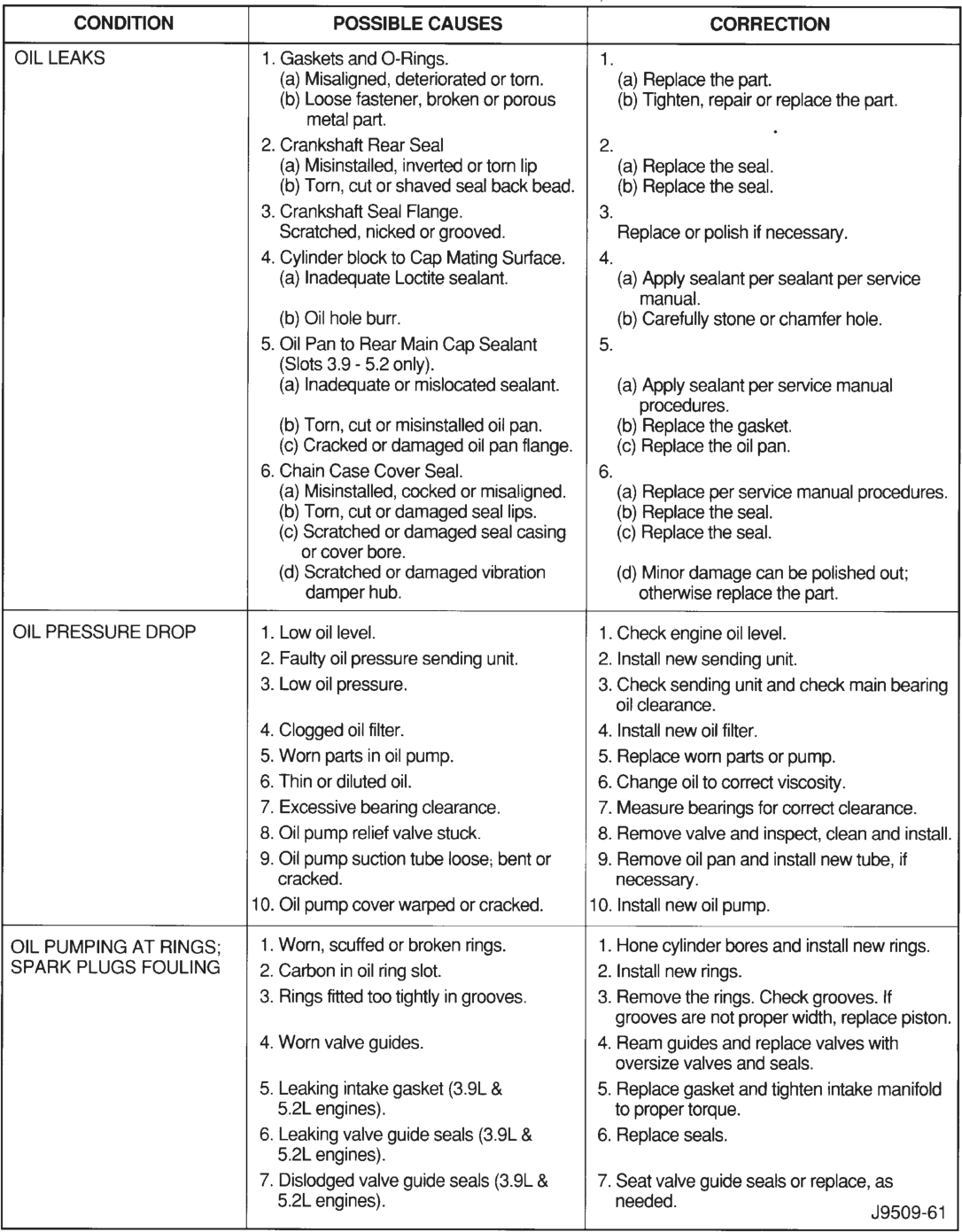
OIL LEAKS 1. Gaskets and O-Rings. 1.
(a) Misaligned, deteriorated or torn. (a) Replace the part.
(b) Loose fastener, broken or porous (b) Tighten, repair or replace the part.
metal part. .
2. Crankshaft Rear Seal 2.
(a) Misinstalled, inverted or torn lip (a) Replace the seal.
(b) Torn, cut or shaved seal back bead. (b) Replace the seal.
3. Crankshaft Seal Flange. 3.
Scratched, nicked or grooved. Replace or polish if necessary.
4. Cylinder block to Cap Mating Surface. | 4.
(a) Inadequate Loctite sealant. (a) Apply sealant per sealant per service
manual.
(b) Oil hole burr. (b) Carefully stone or chamfer hole.
5. Oil Pan to Rear Main Cap Sealant 5.
(Slots 3.9 - 5.2 only).
(a) Inadequate or mislocated sealant. (a) Apply sealant per service manual
procedures.
(b) Torn, cut or misinstalled oil pan. (b) Replace the gasket.
(c) Cracked or damaged oil pan flange. (c) Replace the oil pan.
6. Chain Case Cover Seal. 6.
(a) Misinstalled, cocked or misaligned. (a) Replace per service manual procedures.
(b) Torn, cut or damaged seal lips. (b) Replace the seal.
(c) Scratched or damaged seal casing (c) Replace the seal.
or cover bore.
(d) Scratched or damaged vibration (d) Minor damage can be polished out;
damper hub. otherwise replace the part.
OIL PRESSURE DROP 1. Low oil level. 1. Check engine oil level.
2. Faulty oil pressure sending unit. 2. Install new sending unit.
3. Low oil pressure. 3. Check sending unit and check main bearing
oil clearance.
4. Clogged oil filter. 4. Install new oil filter.
5. Worn parts in oil pump. 5. Replace worn parts or pump.
6. Thin or diluted oil. 6. Change oil to correct viscosity.
7. Excessive bearing clearance. 7. Measure bearings for correct clearance.
8. Oil pump relief valve stuck. 8. Remove valve and inspect, clean and install.
9. Oil pump suction tube loose; bent or 9. Remove oil pan and install new tube, if
cracked. necessary.
10. Oil pump cover warped or cracked. 10. Install new oil pump.
OIL PUMPING AT RINGS; 1. Worn, scuffed or broken rings. 1. Hone cylinder bores and install new rings. |
SPARK PLUGS FOULING =| 2. Carbon in oil ring slot. 2. Install new rings.
3. Rings fitted too tightly in grooves. 3. Remove the rings. Check grooves. If
grooves are not proper width, replace piston.
4. Worn valve guides. 4. Ream guides and replace valves with
oversize valves and seals.
5. Leaking intake gasket (3.9L & 5. Replace gasket and tighten intake manifold
5.2L engines). to proper torque.
6. Leaking valve guide seals (3.9L & 6. Replace seals.
5.2L engines).
7. Dislodged valve guide seals (3.9L & 7. Seat valve guide seals or replace, as
5.2L engines). needed. J9509-61
4.0L ENGINE
INDEX
DESCRIPTION AND OPERATION
ENGINE DESCRIPTION . . . . . . . . . . . . . . . . . . . 15 LUBRICATION SYSTEM . . . . . . . . . . . . . . . . . . . 16 OIL PUMP PRESSURE . . . . . . . . . . . . . . . . . . . . 16 OVERSIZE AND UNDERSIZE COMPONENT
CODES . . . . . . . . . . . . . . . . . . . . . . . . . . . . . . 18 SERVICE PROCEDURES
FITTING CONNECTING ROD BEARINGS . . . . . . 21 FITTING CRANKSHAFT MAIN BEARINGS . . . . . 22 PISTON FITTING . . . . . . . . . . . . . . . . . . . . . . . . 18 PISTON RING FITTING . . . . . . . . . . . . . . . . . . . 19 VALVE TIMING . . . . . . . . . . . . . . . . . . . . . . . . . . 18 REMOVAL AND INSTALLATION
CAMSHAFT PIN REPLACEMENT . . . . . . . . . . . . 38 CAMSHAFT . . . . . . . . . . . . . . . . . . . . . . . . . . . . 36 CRANKSHAFT MAIN BEARINGS . . . . . . . . . . . . 39 ENGINE ASSEMBLY . . . . . . . . . . . . . . . . . . . . . . 27 ENGINE CYLINDER HEAD COVER . . . . . . . . . . 29 ENGINE CYLINDER HEAD . . . . . . . . . . . . . . . . . 31 ENGINE MOUNTS—FRONT . . . . . . . . . . . . . . . . 26 ENGINE MOUNT—REAR . . . . . . . . . . . . . . . . . . 26 HYDRAULIC TAPPETS . . . . . . . . . . . . . . . . . . . . 33 OIL PAN . . . . . . . . . . . . . . . . . . . . . . . . . . . . . . . 41
DESCRIPTION AND OPERATION
ENGINE DESCRIPTION
The 4.0 Liter (242 CID) six-cylinder engine is an In-line, lightweight, overhead valve engine.
Engine Type . . . . . . . . . . . . . . . . . .In-line 6 Cylinder Bore and Stroke . .98.4 x 86.69 mm (3.88 x 3.413 in.) Displacement . . . . . . . . . . . . . . . . . . .4.0 (242 cu. in.) Compression Ratio . . . . . . . . . . . . . . . . . . . . . . .8.7:1 Torque . . . . . . . . . .305 N·m (225 ft. lbs.) @ 4000 rpm Firing Order . . . . . . . . . . . . . . . . . . . . .1–5–3–6–2–4 Lubrication . . . . .Pressure Feed–Full Flow Filtration Engine Oil Capacity . . . . . . . . . . . . .5.7 L (6 Quarts) Cooling System . . .Liquid Cooled–Forced Circulation Cooling System Capacity . . . . . . . .11.4 L (12 Quarts) Cylinder Block. . . . . . . . . . . . . . . . . . . . . . .Cast Iron Crankshaft . . . . . . . . . . . . . . . . . .Cast Nodular Iron Cylinder Head . . . . . . . . . . . . . . . . . . . . . . .Cast Iron Camshaft. . . . . . . . . . . . . . . . . . . . . . . . . . .Cast Iron Pistons. . . . . . . . . . . . .Aluminum Alloy (with Struts) Pistons Combustion Cavity . . . . . . . .Double Quench Connecting Rods . . . . . . . . . . . . . . . . . . . . .Cast Iron page page
OIL PUMP . . . . . . . . . . . . . . . . . . . . . . . . . . . . . 44 PISTONS AND CONNECTING RODS . . . . . . . . . 42 REAR MAIN OIL SEALS . . . . . . . . . . . . . . . . . . . 43 ROCKER ARMS AND PUSH RODS . . . . . . . . . . 30 TIMING CASE COVER OIL SEAL . . . . . . . . . . . . 44 TIMING CASE COVER . . . . . . . . . . . . . . . . . . . . 34 TIMING CHAIN AND SPROCKETS . . . . . . . . . . . 35 VALVE STEM SEAL AND SPRING . . . . . . . . . . . 30 VALVES AND VALVE SPRINGS . . . . . . . . . . . . . 33 VIBRATION DAMPER . . . . . . . . . . . . . . . . . . . . . 34 DISASSEMBLY AND ASSEMBLY
CYLINDER BLOCK . . . . . . . . . . . . . . . . . . . . . . . 47 VALVE SERVICE . . . . . . . . . . . . . . . . . . . . . . . . 45 CLEANING AND INSPECTION
CYLINDER BLOCK . . . . . . . . . . . . . . . . . . . . . . . 48 ENGINE CYLINDER HEAD COVER . . . . . . . . . . 47 ENGINE CYLINDER HEAD . . . . . . . . . . . . . . . . . 47 HYDRAULIC TAPPETS . . . . . . . . . . . . . . . . . . . . 48 ROCKER ARMS AND PUSH RODS . . . . . . . . . . 48 SPECIFICATIONS
4.0L ENGINE SPECIFICATIONS . . . . . . . . . . . . . 49 SPECIAL TOOLS
4.0L ENGINE . . . . . . . . . . . . . . . . . . . . . . . . . . . 52
This engine is designed for unleaded fuel. The engine cylinder head has dual quench-type combustion chambers that create turbulence and fast burning of the air/fuel mixture. This results in good fuel economy.
The cylinders are numbered 1 through 6 from front to rear. The firing order is 1-5-3-6-2-4 (Fig. 1).
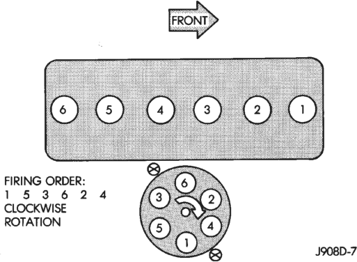
The crankshaft rotation is clockwise, when viewed from the front of the engine. The crankshaft rotates within seven main bearings. The camshaft rotates within four bearings.
BUILD DATE CODE
The engine Build Date Code is located on a machined surface on the right side of the cylinder block between the No.2 and No.3 cylinders (Fig. 2).
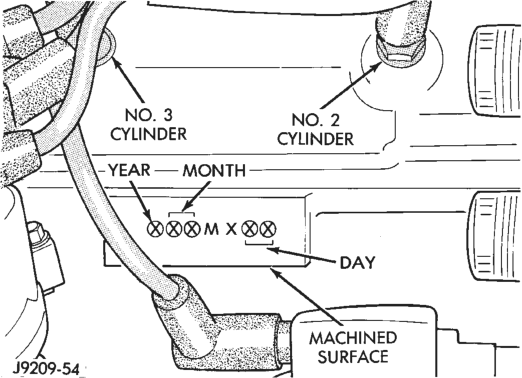
The digits of the code identify: • 1st Digit—The year (5 = 1995). • 2nd & 3rd Digits—The month (01 - 12). • 4th & 5th Digits—The engine type/fuel system/ compression ratio (MX = A 4.0 Liter (242 CID) 8.7:1 compression ratio engine with a multi-point fuel injection system).
• 6th & 7th Digits—The day of engine build (01 - 31). (1) FOR EXAMPLE: Code * 501MX12 * identifies a 4.0 Liter (242 CID) engine with a multi-point fuel injection system, 8.7:1 compression ratio and built on January 12, 1995.
LUBRICATION SYSTEM
A gear—type positive displacement pump is mounted at the underside of the block opposite the No. 4 main bearing. The pump draws oil through the screen and inlet tube from the sump at the rear of the oil pan. The oil is driven between the drive and idler gears and pump body, then forced through the outlet to the block. An oil gallery in the block channels the oil to the inlet side of the full flow oil filter. After passing through the filter element, the oil passes from the center outlet of the filter through an oil gallery that channels the oil up to the main gallery which extends the entire length of the block.
Galleries extend downward from the main oil gallery to the upper shell of each main bearing. The crankshaft is drilled internally to pass oil from the main bearing journals (except number 4 main bearing journal) to the connecting rod journals. Each connecting rod bearing cap has a small squirt hole, oil passes through the squirt hole and is thrown off as the rod rotates. This oil throwoff lubricates the camshaft lobes, distributor drive gear, cylinder walls, and piston pins.
The hydraulic valve tappets receive oil directly from the main oil gallery. Oil is provided to the camshaft bearing through galleries. The front camshaft bearing journal passes oil through the camshaft sprocket to the timing chain. Oil drains back to the oil pan under the number one main bearing cap.
The oil supply for the rocker arms and bridged pivot assemblies is provided by the hydraulic valve tappets which pass oil through hollow push rods to a hole in the corresponding rocker arm. Oil from the rocker arm lubricates the valve train components, then passes down through the push rod guide holes in the cylinder head past the valve tappet area, and returns to the oil pan.
OIL PUMP PRESSURE
The MINIMUM oil pump pressure is 89.6 kPa (13 psi) at 600 rpm. The MAXIMUM oil pump pressure is 255-517 kPa (37-75 psi) at 1600 rpm or more.
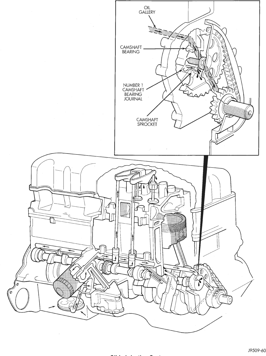
Oil Lubrication System
OVERSIZE AND UNDERSIZE COMPONENT CODES
Some engines may be built with oversize or undersize components such as:
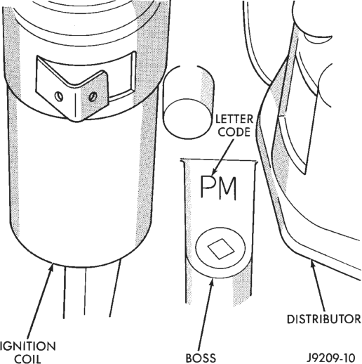
• Oversize cylinder bores. • Oversize camshaft bearing bores. • Undersize crankshaft main bearing journals. • Undersize connecting rod journals. These engines are identified by a letter code (Fig. 3) stamped on a boss between the ignition coil and the distributor (Fig. 4).
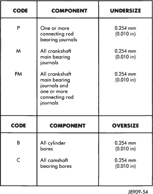
connecting rod (0.010 in)
bearing journals
M All crankshaft 0.254 mm
main bearing (0.010 in)
journals
PM All crankshaft 0.254 mm
main bearing (0.010 in)
journals and
one or more
connecting rod
journals
B All cylinder 0.254 mm
bores (0.010 in)
Cc All camshaft 0.254 mm
bearing bores (0.010 in)
: J8909-54
SERVICE PROCEDURES
VALVE TIMING
Disconnect the spark plug wires and remove the spark plugs.
Remove the engine cylinder head cover. Remove the capscrews, bridge and pivot assembly, and rocker arms from above the No.1 cylinder.
Alternately loosen each capscrew, one turn at a time, to avoid damaging the bridge.
Rotate the crankshaft until the No.6 piston is at top dead center (TDC) on the compression stroke.
Rotate the crankshaft counterclockwise (viewed from the front of the engine) 90°.
Install a dial indicator on the end of the No.1 cylinder intake valve push rod. Use rubber tubing to secure the indicator stem on the push rod.
Location
Set the dial indicator pointer at zero. Rotate the crankshaft clockwise (viewed from the front of the engine) until the dial indicator pointer indicates 0.305 mm (0.012 inch) travel distance (lift).
The timing notch index on the vibration damper should be aligned with the TDC mark on the timing degree scale.
If the timing notch is more than 13 mm (1/2 inch) away from the TDC mark in either direction, the valve timing is incorrect.
If the valve timing is incorrect, the cause may be a broken camshaft pin. It is not necessary to replace the camshaft because of pin failure. A spring pin is available for service replacement.
PISTON FITTING
BORE GAGE METHOD
(1) To correctly select the proper size piston, a cylinder bore gauge, capable of reading in 0.003 mm ( .0001 in.) INCREMENTS is required. If a bore gauge is not available, do not use an inside micrometer.
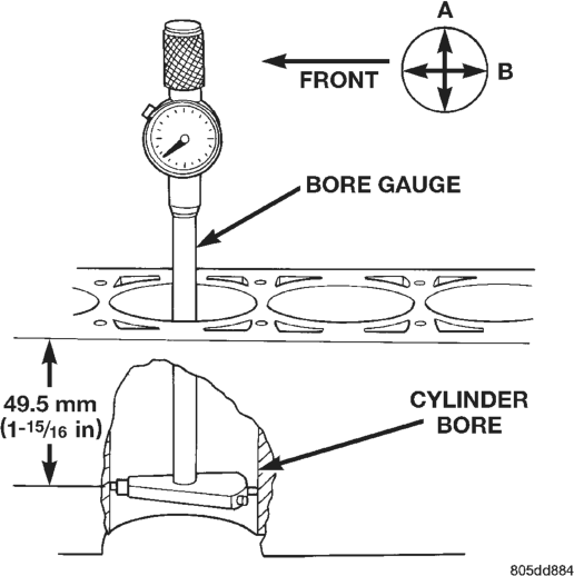
(2) Measure the inside diameter of the cylinder bore at a point 49.5 mm (1-15/16 inches) below top of bore. Start perpendicular (across or at 90 degrees) to the axis of the crankshaft at point A and then take an additional bore reading 90 degrees to that at point B (Fig. 5).
(3) The coated pistons will be serviced with the piston pin and connecting rod pre-assembled. The coated piston connecting rod assembly can be used to service previous built engines and
MUST be replaced as complete sets. Tin coated pistons should not be used as replacements for coated pistons.
(4) The coating material is applied to the piston after the final piston machining process. Measuring the outside diameter of a coated piston will not provide accurate results. Therefore measuring the inside diameter of the cylinder bore with a dial Bore Gauge is MANDATORY.. To correctly select the proper size piston, a cylinder bore gauge capable of reading in 0.003 mm ( .0001 in.) increments is required. (5) Piston installation into the cylinder bore requires slightly more pressure than that required for non-coated pistons. The bonded coating on the piston will give the appearance of a line-to-line fit with the cylinder bore.
PISTON SIZE CHART
CYLINDER BORE SIZE PISTON LETTER SIZE 98.438 to 98.448 mm (3.8755 to 3.8759 in.) . . . . . . .A 98.448 to 98.458 mm (3.8759 to 3.8763 in.) . . . . . . .B 98.458 to 98.468 mm (3.8763 to 3.8767 in.) . . . . . . .C 98.468 to 98.478 mm (3.8767 to 3.8771 in.) . . . . . . .D 98.478 to 98.488 mm (3.8771 to 3.8775 in.) . . . . . . .E 98.488 to 98.498 mm (3.8775 to 3.8779 in.) . . . . . . .F
PISTON RING FITTING
(1) Carefully clean the carbon from all ring grooves. Oil drain openings in the oil ring groove and pin boss must be clear. DO NOT remove metal from the grooves or lands. This will change ring-to-groove clearances and will damage the ring-to-land seating.
(2) Be sure the piston ring grooves are free of nicks and burrs.
(3) Measure the ring side clearance with a feeler gauge fitted snugly between the ring land and ring (Fig. 6) (Fig. 7). Rotate the ring in the groove. It must move freely around circumference of the groove.
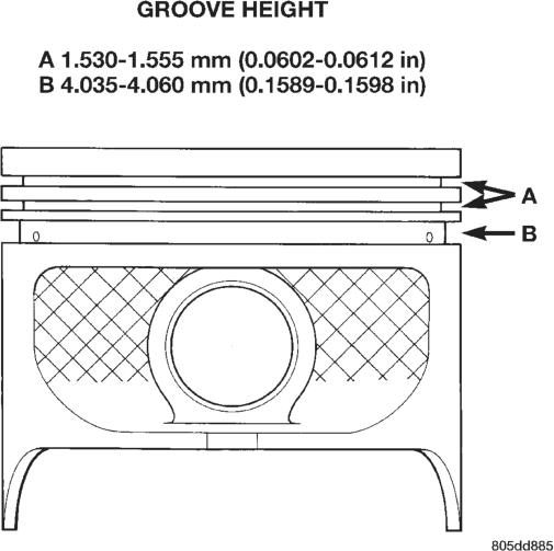
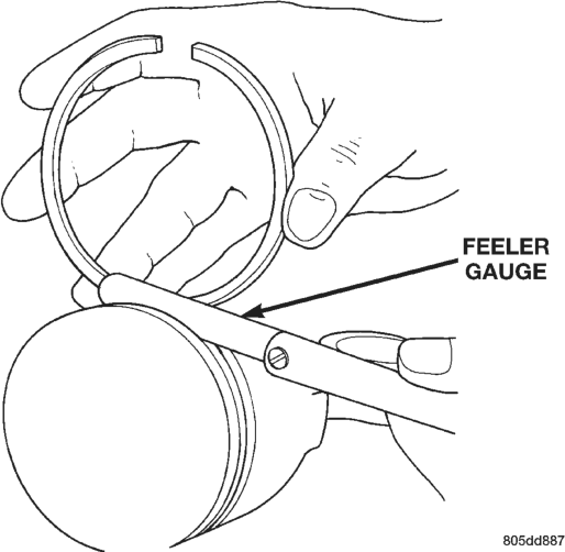
Ring Side Clearance Measurement
Top Compression Ring . . . . . . . . . .0.042to 0.084 mm
(0.0017 to 0.0033 in.) Second Compression Ring. . . . . . . .0.042to 0.084 mm
(0.0017 to 0.0033 in.) Oil Control Ring . . . . . . . . . . . . . . . .0.06 to 0.21 mm
(0.0024 to 0.0083 in.)
(4) Place ring in the cylinder bore and push down with inverted piston to position near lower end of the ring travel. Measure ring gap with a feeler gauge fitting snugly between ring ends (Fig. 8).
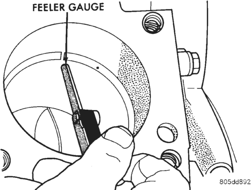
Ring Gap Measurement
Top Compression Ring . . . . . . . . . 0.229 to 0.610 mm
(0.0090 to 0.0240 inch) Second Compresion Ring. . . . . . . .0.483 to 0.965 mm
(0.0190 to 0.0380 inch) Oil Control Ring . . . . . . . . . . . . . .0.254 to 1.500 mm
(0.010 to 0.060 inch)
(5) Install the oil control rings according to instructions in the package. It is not necessary to use a tool to install the upper and lower rails. Insert oil rail spacer first, then side rails.
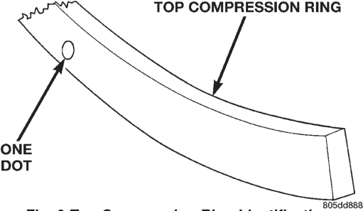
(6) The two compression rings are different and cannot be interchanged. The TOP compression ring can be identified by 1 dot on the top surface of the ring (Fig. 9).
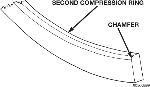
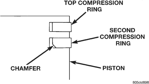
(7) The second compression ring has a chamfer on the BOTTOM of the inside edge (Fig. 10).
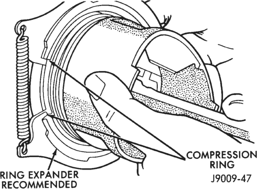
(8) Using a ring installer, install the second compression ring with the chamfer facing down (Fig. 11) (Fig. 12).
(9) The top compression ring has a dot located on the top surface (Fig. 9).
(10) Using a ring installer, install the top ring with the dot facing up (Fig. 12).
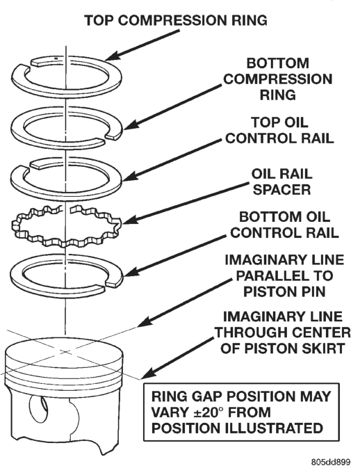
(11) Position the gaps on the piston (Fig. 13): • Oil spacer - Gap on center line of piston pin bore. • Oil rails - Gap 180° apart on centerline of piston skirt.
• No. 2 Compression ring - Gap 180° from top oil rail gap.
• No. 1 Compression ring - Gap 180° from No. 2 compression ring gap.
FITTING CONNECTING ROD BEARINGS
INSPECTION
BEARINGS
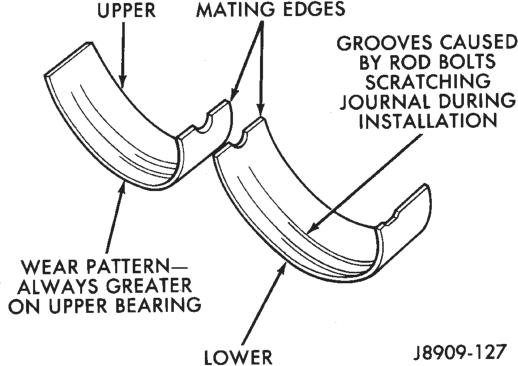
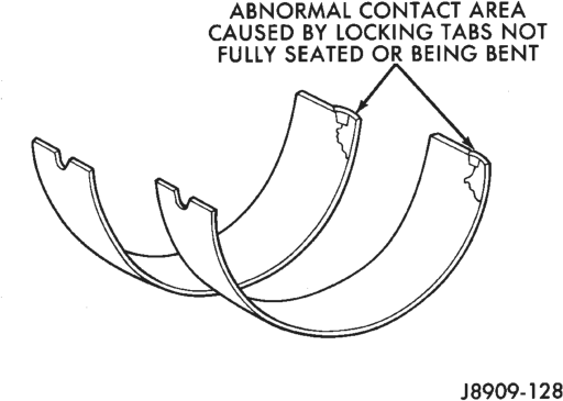
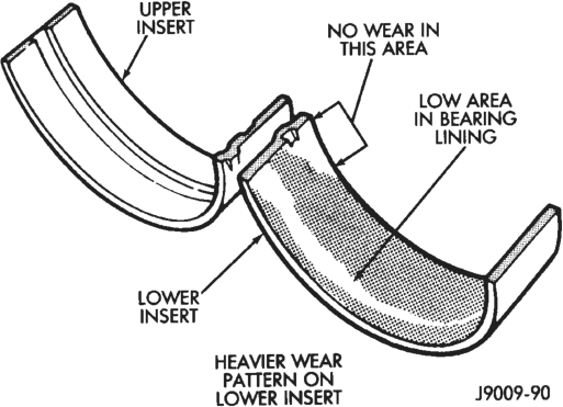
Inspect the connecting rod bearings for scoring and bent alignment tabs (Fig. 14) (Fig. 15). Check the bearings for normal wear patterns, scoring, grooving, fatigue and pitting (Fig. 16). Replace any bearing that shows abnormal wear.
Inspect the connecting rod journals for signs of scoring, nicks and burrs.
CONNECTING RODS
Misaligned or bent connecting rods can cause abnormal wear on pistons, piston rings, cylinder walls, connecting rod bearings and crankshaft connecting rod journals. If wear patterns or damage to any of these components indicate the probability of a
or by Damaged Crankshaft Pin Journal misaligned connecting rod, inspect it for correct rod alignment. Replace misaligned, bent or twisted connecting rods.
BEARING-TO-JOURNAL CLEARANCE
(1) Wipe the oil from the connecting rod journal. (2) Use short rubber hose sections over rod bolts during installation.
(3) Lubricate the upper bearing insert and install in connecting rod.
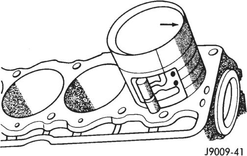
(4) Use piston ring compressor to install the rod and piston assemblies. The oil squirt holes in the rods must face the camshaft. The arrow on the piston crown should point to the front of the engine (Fig. 17). Verify that the oil squirt holes in the rods face the camshaft and that the arrows on the pistons face the front of the engine.
(5) Install the lower bearing insert in the bearing cap. The lower insert must be dry. Place strip of Plastigage across full width of the lower insert at the center of bearing cap. Plastigage must not crumble in use. If brittle, obtain fresh stock.
(6) Install bearing cap and connecting rod on the journal and tighten nuts to 45 N·m (33 ft. lbs.) torque. DO NOT rotate crankshaft. Plastigage will smear, resulting in inaccurate indication.
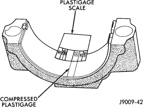
(7) Remove the bearing cap and determine amount of bearing-to- journal clearance by measuring the width of compressed Plastigage (Fig. 18). Refer to Engine Specifications for the proper clearance. Plastigage should indicate the same clearance across the entire width of the insert. If the clearance varies, it may be caused by either a tapered journal, bent connecting rod or foreign material trapped between the insert and cap or rod.
(8) If the correct clearance is indicated, replacement of the bearing inserts is not necessary. Remove the Plastigage from crankshaft journal and bearing insert. Proceed with installation.
(9) If bearing-to-journal clearance exceeds the specification, install a pair of 0.0254 mm (0.001 inch) undersize bearing inserts. All the odd size inserts must be on the bottom. The sizes of the service replacement bearing inserts are stamped on the backs of the inserts. Measure the clearance as described in the previous steps.
(10) The clearance is measured with a pair of 0.0254 mm (0.001 inch) undersize bearing inserts installed. This will determine if two 0.0254 mm (0.001 inch) undersize inserts or another combination is needed to
Plastigage provide the correct clearance (refer to Connecting Rod Bearing Fitting Chart).
(11) FOR EXAMPLE: If the initial clearance was 0.0762 mm (0.003 inch), 0.025 mm (0.001 inch) undersize inserts would reduce the clearance by 0.025 mm (0.001 inch). The clearance would be 0.002 inch and within specification. A 0.051 mm (0.002 inch) undersize insert would reduce the initial clearance an additional 0.013 mm (0.0005 inch). The clearance would then be 0.038 mm (0.0015 inch).
(12) Repeat the Plastigage measurement to verify your bearing selection prior to final assembly.
(13) Once you have selected the proper insert, install the insert and cap. Tighten the connecting rod bolts to 45 N·m (33 ft. lbs.) torque.
SIDE CLEARANCE MEASUREMENT
Slide snug-fitting feeler gauge between the connecting rod and crankshaft journal flange. Refer to Engine Specifications for the proper clearance. Replace the connecting rod if the side clearance is not within specification.
FITTING CRANKSHAFT MAIN BEARINGS
INSPECTION
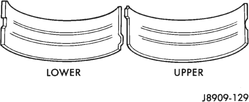
Wipe the inserts clean and inspect for abnormal wear patterns and for metal or other foreign material imbedded in the lining. Normal main bearing insert wear patterns are illustrated (Fig. 19).
NOTE: If any of the crankshaft journals are scored, remove the engine for crankshaft repair.
Inspect the back of the inserts for fractures, scrapings or irregular wear patterns.
Inspect the upper insert locking tabs for damage. Replace all damaged or worn bearing inserts.
CONNECTING ROD BEARING FITTING CHART
FITTING BEARINGS (CRANKSHAFT INSTALLED)
The main bearing caps, numbered (front to rear) from 1 through 7 have an arrow to indicate the forward position. The upper main bearing inserts are grooved to provide oil channels while the lower inserts are smooth.
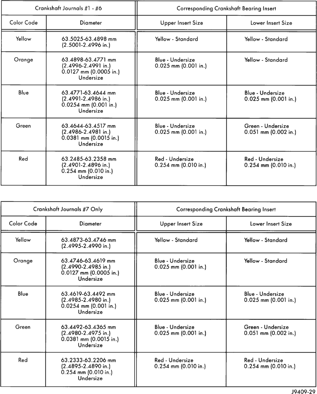
Each bearing insert pair is selectively fitted to its respective journal to obtain the specified operating clearance. In production, the select fit is obtained by using various-sized color-coded bearing insert pairs as listed in the Main Bearing Fitting Chart. The bearing color code appears on the edge of the insert. The size is not stamped on bearing inserts used for engine production.
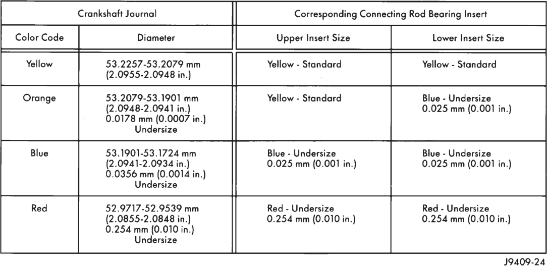
The main bearing journal size (diameter) is identified by a color-coded paint mark on the adjacent cheek. The rear main journal, is identified by a colorcoded paint mark on the crankshaft rear flange.
When required, upper and lower bearing inserts of different sizes may be used as a pair. A standard size insert is sometimes used in combination with a 0.025 mm (0.001 inch) undersize insert to reduce the clearance by 0.013 mm (0.0005 inch). Never use a pair of bearing inserts with greater than a 0.025 mm (0.001 inch) difference in size (Fig. 20).
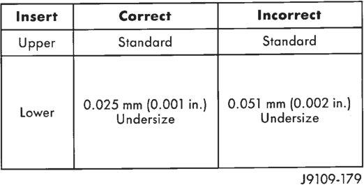
NOTE: When replacing inserts, the odd size inserts must be either all on the top (in cylinder block) or all on the bottom (in main bearing cap).
Once the bearings have been properly fitted, proceed to Crankshaft Main Bearing—Installation.
BEARING-TO-JOURNAL CLEARANCE (CRANKSHAFT INSTALLED)
When using Plastigage, check only one bearing clearance at a time.
Install the grooved main bearings into the cylinder block and the non-grooved bearings into the bearing caps.
Install the crankshaft into the upper bearings dry. Place a strip of Plastigage across full width of the crankshaft journal to be checked.
Install the bearing cap and tighten the bolts to 108 N·m (80 ft. lbs.) torque.
NOTE: DO NOT rotate the crankshaft. This will cause the Plastigage to shift, resulting in an inaccurate reading. Plastigage must not be permitted to crumble. If brittle, obtain fresh stock.
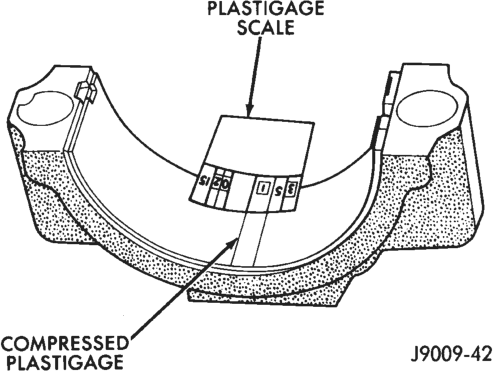
Remove the bearing cap. Determine the amount of clearance by measuring the width of the compressed Plastigage with the scale on the Plastigage envelope (Fig. 21). Refer to Engine Specifications for the proper clearance.
Plastigage
Plastigage should indicate the same clearance across the entire width of the insert. If clearance varies, it may indicate a tapered journal or foreign material trapped behind the insert.
If the specified clearance is indicated and there are no abnormal wear patterns, replacement of the bearing inserts is not necessary. Remove the Plastigage from the crankshaft journal and bearing insert. Proceed to Crankshaft Main Bearing—Installation.
If the clearance exceeds specification, install a pair of 0.025 mm (0.001 inch) undersize bearing inserts and measure the clearance as described in the previous steps.
The clearance indicate with the 0.025 mm (0.001 inch) undersize insert pair installed will determine if this insert size or some other combination will provide the specified clearance. FOR EXAMPLE: If the clearance was 0q762 mm (0.003 inch) originally, a pair of 0.0254 mm (0.001 inch) undersize inserts would reduce the clearance by 0.0254 mm (0.001 inch). The clearance would then be 0.0508 mm (0.002 inch) and within the specification. A 0.051 mm (0.002 inch) undersize bearing insert and a 0.0254 mm (0.001 inch) undersize insert would reduce the original clearance an additional 0.0127 mm (0.0005 inch). The clearance would then be 0.0381 mm (0.0015 inch).
CAUTION: Never use a pair of inserts that differ more than one bearing size as a pair.
FOR EXAMPLE: DO NOT use a standard size upper insert and a 0.051 mm (0.002 inch) undersize lower insert.
If the clearance exceeds specification using a pair of 0.051 mm (0.002 inch) undersize bearing inserts, measure crankshaft journal diameter with a micrometer. If the journal diameter is correct, the crankshaft bore in the cylinder block may be misaligned, which requires cylinder block replacement or machining to true bore.
Replace the crankshaft or grind to accept the appropriate undersize bearing inserts if:
• Journal diameters 1 through 6 are less than 63.4517 mm (2.4981 inches) • Journal 7 diameter is less than 63.4365 mm (2.4975 inches).
Once the proper clearances have been obtained, proceed to Crankshaft Main Bearing—Installation.
MAIN BEARING JOURNAL DIAMETER (CRANKSHAFT REMOVED)
Remove the crankshaft from the cylinder block (refer to Cylinder Block - Disassemble).
Clean the oil off the main bearing journal. Determine the maximum diameter of the journal with a micrometer. Measure at two locations 90° apart at each end of the journal.
The maximum allowable taper and out of round is 0.013 mm (0.0005 inch). Compare the measured diameter with the journal diameter specification (Main Bearing Fitting Chart). Select inserts required to obtain the specified bearing-to-journal clearance.
Install the crankshaft into the cylinder block (refer to Cylinder Block - Assemble and Crankshaft Main Bearings - Installation).
MAIN BEARING FITTING CHART
REMOVAL AND INSTALLATION
ENGINE MOUNTS—FRONT
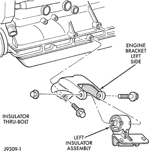
The front mounts support the engine at each side. These insulators are made of resilient rubber.
REMOVAL
(1) Disconnect the negative cable from the battery. (2) Support the engine. (3) Raise the vehicle. (4) Remove the insulator assembly-to-lower front sill bolts (Fig. 22) (Fig. 23).
(5) Raise the engine slightly. (6) Remove the thru-bolt nut and thru-bolt (Fig. 22) (Fig. 23). Remove the insulator.
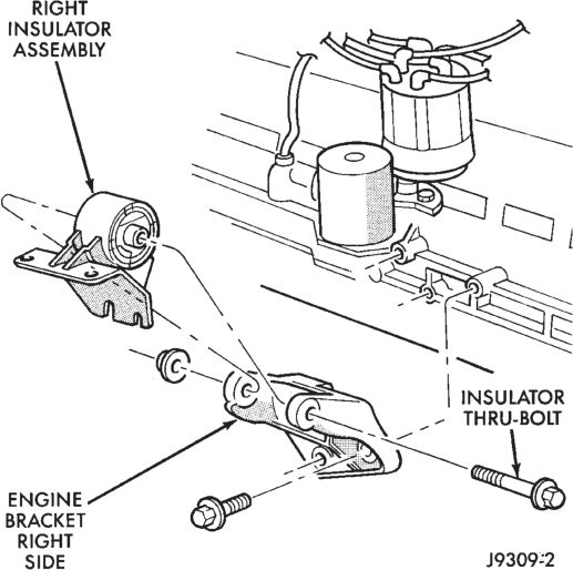
(7) If required, remove the engine bracket from the block (Fig. 22) (Fig. 23).
INSTALLATION
(1) If removed, install the engine bracket to the block (Fig. 22) (Fig. 23). Tighten the bolts to 61 N·m (45 ft. lbs.) torque.
(2) Install the insulator assembly to the lower front sill. Tighten the bolts to 65 N·m (48 ft. lbs.) torque.
(3) With the engine insulator assembly and engine bracket in position, install the thru-bolt and nut (Fig. 22) (Fig. 23). Tighten the thru- bolt nut to 121 N·m (89 ft. lbs.) torque.
(4) Lower the vehicle. (5) Remove the engine support. (6) Connect the negative cable to the battery.
ENGINE MOUNT—REAR
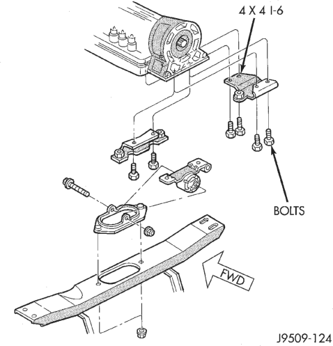
A resilient rubber cushion bracket assembly supports the transmission at the rear. This bracket is attached to the crossmember (Fig. 24).
REMOVAL
(1) Disconnect the negative cable from the battery. (2) Raise the vehicle and support the transmission. (3) Remove the nuts holding the clevis bracket to the crossmember (Fig. 24).
(4) Raise the transmission SLIGHTLY. (5) Remove the thru-bolt and nut (Fig. 24). Remove the rear mount bracket clevis.
(6) Remove the bolts holding the rear mount bracket to the transmission (Fig. 24). Remove the bracket from the exhaust pipe hanger. Remove the bracket.
INSTALLATION
(1) Position the rear mount bracket onto the exhaust hanger. Position the rear mount bracket assembly onto the transmission and install the bolts (Fig. 24). Tighten the bolts to the proper torque:
• MANUAL TRANSMISSION—Tighten to 46 N·m (34 ft. lbs.) torque.
• AUTOMATIC TRANSMISSION—Tighten to 75 N·m (55 ft. lbs.) torque.
(2) Install the thru-bolt into the rear mount bracket and clevis (Fig. 24). Finger tighten the nut at this time.
(3) Lower the transmission until the clevis bracket studs are in position on the crossmember (Fig. 24). Install the clevis bracket stud nuts. Tighten the nuts to 41 N·m (30 ft. lbs) torque.
(4) Tighten the thru-bolt nut to 121 N·m (89 ft. lbs.) torque.
(5) Remove the transmission support. (6) Lower the vehicle. (7) Connect the negative cable to the battery.
ENGINE ASSEMBLY
REMOVAL
(1) Disconnect the battery cables. Remove the battery.
(2) Mark the hinge locations on the hood panel for alignment reference during installation. Remove the engine compartment lamp. Remove the hood.
(3) Remove the radiator drain cock and radiator cap to drain the coolant. DO NOT waste usable coolant. If the solution is clean, drain the coolant into a clean container for reuse.
(4) Remove the upper radiator hose and coolant recovery hose (Fig. 25).
(5) Remove the lower radiator hose. (6) Remove upper radiator support retaining bolts and remove radiator support.
(7) Remove the fan assembly from the water pump.
(8) Remove the fan shroud (Fig. 25). (9) Disconnect the transmission fluid cooler tubing (automatic transmission).
(10) Vehicles with Air Conditioning:
(a) Discharge the A/C system (refer to Group 24, Heating and Air Conditioning).
(b) Remove the service valves and cap the compressor ports.
(11) Remove the radiator or radiator/condenser (if equipped with A/C).
(12) Disconnect the heater hoses at the engine thermostat housing and water pump (Fig. 25).
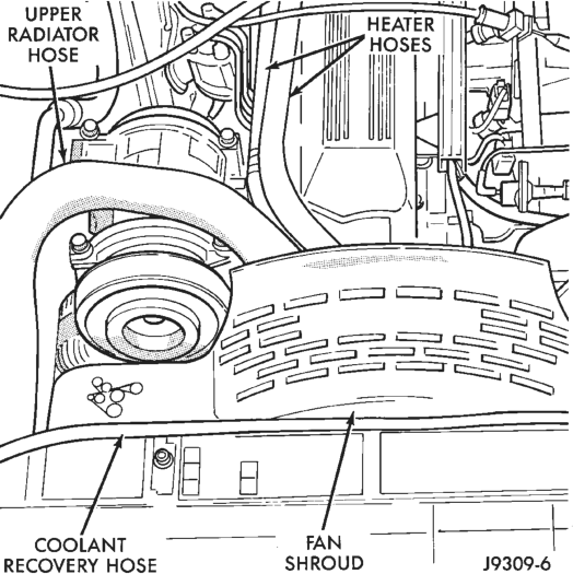
Hose, Fan Shroud & Heater hoses
(13) Disconnect the throttle linkages (Fig. 26). (14) Disconnect the vehicle speed control cable (if equipped) (Fig. 26).
(15) Disconnect the line pressure cable (if equipped with automatic transmission).
(16) Disconnect injection system wire harness connector at each injector. Mark the wires for proper installation.
(17) Disconnect the distributor electrical connection and the oil pressure switch connector.
(18) Disconnect the quick-connect fuel lines at the fuel rail and return line by squeezing the two retaining tabs against the fuel tube (Fig. 26). Pull the fuel tube and retainer from the quick-connect fitting (refer to Group 14, Fuel System for the proper procedure).
(19) Remove the fuel line bracket from the intake manifold.
(20) Remove the air cleaner assembly (Fig. 27). (21) Remove the power brake vacuum check valve from the booster, if equipped.
(22) Vehicles with Power Steering (Fig. 27):
(a) Disconnect the hoses from the fittings at the steering gear.
(b) Drain the pump reservoir.
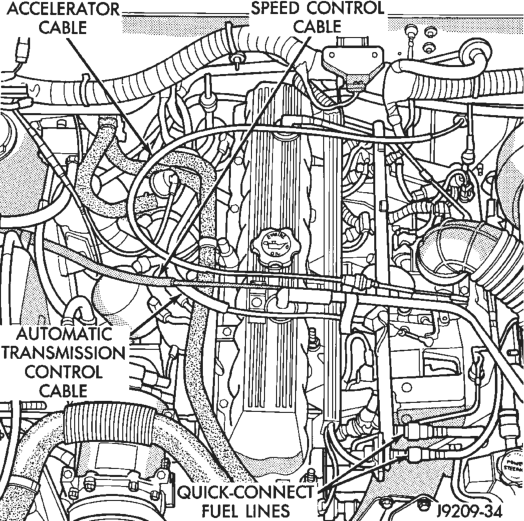
Cable, Automatic Transmission Control Cable &
Quick-Connect Fuel Lines
(c) Cap the fittings on the hoses and steering gear to prevent foreign objects from entering the system.
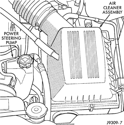
Pump
(23) Identify, tag and disconnect all necessary wire connectors and vacuum hoses.
(24) Raise and support the vehicle.
(25) Disconnect the wires from the engine starter motor solenoid.
(26) Remove the engine starter motor. (27) Disconnect the oxygen sensor from the exhaust pipe.
(28) Disconnect the exhaust pipe from the manifold.
(29) Disconnect the vehicle speed sensor wire connection.
(30) Remove the exhaust pipe support. (31) Remove the engine flywheel/converter housing access cover.
(32) Vehicles with Automatic Transmission:
(a) Mark the converter and drive plate location. (b) Remove the converter-to-drive plate bolts. (33) Remove the upper engine flywheel/converter housing bolts and loosen the bottom bolts.
(34) Remove the engine mount cushion-to-engine compartment bracket bolts.
(35) Lower the vehicle. (36) Attach a lifting device to the engine. (37) Raise the engine off the front supports. (38) Place a support or floor jack under the converter (or engine flywheel) housing.
(39) Remove the remaining converter (or engine flywheel) housing bolts.
(40) Lift the engine out of the engine compartment.
INSTALLATION
CAUTION: When installing the engine into a vehicle equipped with an automatic transmission, be careful not to damage the trigger wheel on the engine flywheel.
(1) Attach a lifting device to the engine and lower the engine into the engine compartment. For easier installation, it may be necessary to remove the engine mount bracket as an aid in alignment of the engine to the transmission.
(2) Vehicles with Manual Transmission:
(a) Insert the transmission shaft into the clutch spline.
(b) Align the engine flywheel housing with the engine.
(c) Install and tighten the engine flywheel housing lower bolts finger tight. (3) Vehicles with Automatic Transmission:
(a) Align the transmission torque converter housing with the engine.
(b) Loosely install the converter housing lower bolts and install the next higher bolt and nut on each side.
(c) Tighten all 4 bolts finger tight. (4) Install the engine mount brackets (if removed).
(5) Lower the engine and engine mount brackets onto the engine compartment cushions. Install the bolts and finger tighten the nuts.
(6) Remove the engine lifting device. (7) Raise and support the vehicle. (8) Install the remaining engine flywheel/converter housing bolts. Tighten all bolts to 38 N·m (28 ft. lbs.) torque.
(9) Vehicles with Automatic Transmission:
(a) Install the converter-to-drive plate bolts. (b) Ensure the installation reference marks are aligned. (10) Install the engine flywheel/converter housing access cover.
(11) Install the exhaust pipe support and tighten the screw.
(12) Tighten the engine mount-to-bracket bolts. (13) Connect the vehicle speed sensor wire connections and tighten the screws.
(14) Connect the exhaust pipe to the manifold. (15) Install the engine starter motor and connect the cable.
(16) Connect the wires to the engine starter motor solenoid.
(17) Lower the vehicle. (18) Connect all the vacuum hoses and wire connectors identified during engine removal.
(19) Vehicles equipped with Power Steering:
(a) Remove the protective caps (b) Connect the hoses to the fittings at the steering gear. Tighten the nut to 52 N·m (38 ft. lbs.) torque.
(c) Fill the pump reservoir with fluid. (20) Install the power brake vacuum check valve from the booster, if equipped.
(21) Connect the fuel inlet and return hoses at the fuel rail. Verify that the quick-connect fitting assembly fits securely over the fuel lines by giving the fuel lines a firm tug.
(22) Install the fuel line bracket to the intake manifold.
(23) Connect the distributor electrical connector and oil pressure switch connector.
(24) Connect the injection system wires to the injectors.
(25) Connect the line pressure cable (if equipped with automatic transmission).
(26) Connect the vehicle speed control cable, if equipped.
(27) Connect the throttle cable linkages. (28) Connect the heater hoses at the engine thermostat housing and water pump.
(29) Install the fan assembly to the water pump. (30) Place the fan shroud in position over the fan. (31) Install the radiator or radiator/condenser (if equipped with A/C).
(32) Connect the service valves to the A/C compressor ports, if equipped with A/C.
(33) Charge the air conditioner system (refer to Group 24, Heating and Air Conditioning).
(34) Connect the radiator hoses and automatic transmission fluid cooler pipes, if equipped.
(35) Install the fan shroud to the radiator or radiator/condenser (if equipped with A/C).
(36) Install upper radiator support. (37) Connect the upper radiator hose and tighten the clamp.
(38) Connect the lower radiator hose and tighten the clamp.
(39) Fill the cooling system with reusable coolant or new coolant (refer to Group 7, Cooling System).
(40) Align the hood to the scribe marks. Install the hood.
(41) Connect the vacuum harness connector.
(a) Firmly push the connectors together ensuring that the retaining tabs are engaged.
(b) Insert the vacuum connector assembly into the retaining bracket on the intake manifold. (42) Install the air cleaner assembly. (43) Install the battery and connect the battery cable.
WARNING: USE EXTREME CAUTION WHEN THE ENGINE IS OPERATING. DO NOT STAND IN A DIRECT LINE WITH THE FAN. DO NOT PUT YOUR HANDS NEAR THE PULLEYS, BELTS OR FAN. DO NOT WEAR LOOSE CLOTHING.
(44) Start the engine, inspect for leaks and correct the fluid levels, as necessary.
ENGINE CYLINDER HEAD COVER
The cylinder head cover is isolated from the cylinder head via grommets and a molded rubber gasket. The grommet and limiter are retained in the cylinder head cover.
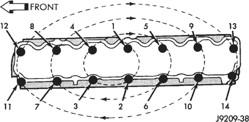
There are two cylinder head bolts that have a pin to locate the cylinder head cover, they are located at position 8 and 9 (Fig. 29)
REMOVAL
(1) Disconnect negative cable from battery. (2) Disconnect the Crankcase Ventilation (CCV) vacuum hose from engine cylinder head cover (Fig. 28). (3) Disconnect the fresh air inlet hose from the engine cylinder head cover (Fig. 28).
(4) Remove the engine cylinder head cover mounting bolts.
(5) Remove the engine cylinder head cover.
INSTALLATION
(1) If a replacement cover is installed, transfer the CCV valve grommet and oil filler cap from the original cover to the replacement cover.
(2) Install engine cylinder head cover. Tighten the mounting bolts to 13 N·m (115 in. lbs.) torque.
(3) Connect the CCV hoses (Fig. 28). (4) Connect negative cable to battery.
ROCKER ARMS AND PUSH RODS
This procedure can be done with the engine in or out of the vehicle.
REMOVAL
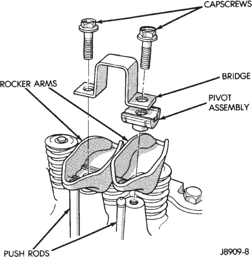
(1) Remove the engine cylinder head cover. (2) Remove the capscrews at each bridge and pivot assembly (Fig. 30). Alternately loosen the capscrews one turn at a time to avoid damaging the bridges.
(3) Check for rocker arm bridges which are causing misalignment of the rocker arm to valve tip area.
(4) Remove the bridges, pivots and corresponding pairs of rocker arms (Fig. 30). Place them on a bench in the same order as removed.
(5) Remove the push rods and place them on a bench in the same order as removed.
INSTALLATION
(1) Lubricate the ball ends of the push rods with Mopar Engine Oil Supplement, or equivalent and install push rods in their original locations. Ensure that the bottom end of each push rod is centered in the tappet plunger cap seat.
(2) Using Mopar Engine Oil Supplement, or equivalent, lubricate the area of the rocker arm that the pivot contacts. Install rocker arms, pivots and bridge above each cylinder in their originally position.
(3) Loosely install the capscrews through each bridge.
(4) At each bridge, tighten the capscrews alternately, one turn at a time, to avoid damaging the bridge. Tighten the capscrews to 28 N·m (21 ft. lbs.) torque.
(5) Install the engine cylinder head cover.
VALVE STEM SEAL AND SPRING
This procedure can be done with the engine cylinder head installed on the block.
REMOVAL
Inspect the valve stems, especially the grooves. An Arkansas smooth stone should be used to remove nicks and high spots.
Each valve spring is held in place by a retainer and a set of conical valve locks. The locks can be removed only by compressing the valve spring.
(1) Remove the engine cylinder head cover. (2) Remove capscrews, bridge and pivot assemblies and rocker arms for access to each valve spring to be removed.
(3) Remove push rods. Retain the push rods, bridges, pivots and rocker arms in the same order and position as removed.
(4) Inspect the springs and retainer for cracks and possible signs of weakening.
(5) Remove the spark plug(s) adjacent to the cylinder(s) below the valve springs to be removed.
(6) Connect an air hose to the adapter and apply air pressure slowly. Maintain at least 621 kPa (90 psi) of air pressure in the cylinder to hold the valves against their seats. For vehicles equipped with an air conditioner, use a flexible air adaptor when servicing the No.1 cylinder.
(7) Tap the retainer or tip with a rawhide hammer to loosen the lock from the retainer. Use Valve Spring Compressor Tool MD-998772A to compress the spring and remove the locks (Fig. 31).
(8) Remove valve spring and retainer (Fig. 31). (9) Remove valve stem oil seals (Fig. 31). Note the valve seals are different for intake and exhaust valves. The top of each seal is marked either INT (Intake) or EXH (Exhaust). DO NOT mix the seals.
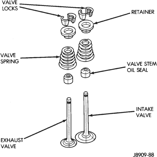
INSTALLATION
CAUTION: Install oil seals carefully to prevent damage from the sharp edges of the valve spring lock grove.
(1) Lightly push the valve seal over the valve stem and valve guide boss. Be sure the seal is completely seated on the valve guide boss.
(2) Install valve spring and retainer.
(3) Compress the valve spring with Valve Spring Compressor Tool MD-998772A and insert the valve locks. Release the spring tension and remove the tool. Tap the spring from side-to-side to ensure that the spring is seated properly on the engine cylinder head.
(4) Disconnect the air hose. Remove the adaptor from the spark plug hole and install the spark plug.
(5) Repeat the procedures for each remaining valve spring to be removed.
(6) Install the push rods. Ensure the bottom end of each rod is centered in the plunger cap seat of the hydraulic valve tappet.
(7) Install the rocker arms, pivots and bridge at their original location.
(8) Tighten the bridge capscrews alternately, one at a time, to avoid damaging the bridge. Tighten the capscrews to 28 N·m (21 ft. lbs.) torque.
(9) Install the engine cylinder head cover.
ENGINE CYLINDER HEAD
This procedure can be done with the engine in or out of the vehicle.
REMOVAL
(1) Disconnect negative cable from battery.
WARNING: DO NOT REMOVE THE CYLINDER BLOCK DRAIN PLUGS OR LOOSEN THE RADIATOR DRAIN COCK WITH THE SYSTEM HOT AND PRES- SURIZED BECAUSE SERIOUS BURNS FROM THE COOLANT CAN OCCUR.
(2) Drain the coolant and disconnect the hoses at the engine thermostat housing. DO NOT waste reusable coolant. If the solution is clean and is being drained only to service the engine or cooling system, drain the coolant into a clean container for reuse.
(3) Remove the air cleaner assembly. (4) Remove the engine cylinder head cover. (5) Remove the capscrews, bridge and pivot assemblies and rocker arms.
(6) Remove the push rods. Retain the push rods, bridges, pivots and rocker arms in the same order as removed.
(7) Loosen the serpentine drive belt at the power steering pump, if equipped or at the idler pulley (refer to Group 7, Cooling System for the proper procedure).
(8) If equipped with air conditioning, perform the following:
(a) Remove the bolts from the A/C compressor mounting bracket and set the compressor aside.
(b) Remove the air conditioner compressor bracket bolts from the engine cylinder head.
(c) Loosen the through bolt at the bottom of the bracket.
(9) If equipped, disconnect the power steering pump bracket. Set the pump and bracket aside. DO NOT disconnect the hoses.
(10) Perform the Fuel System Pressure Release procedure (refer to Group 14, Fuel System).
(11) Remove the fuel lines and vacuum advance hose. (12) Remove the intake and engine exhaust manifolds from the engine cylinder head (refer to Group 11, Exhaust System and Intake Manifold for the proper procedures).
(13) Disconnect the ignition wires and remove the spark plugs.
(14) Disconnect the temperature sending unit wire connector.
(15) Remove the ignition coil and bracket assembly. (16) Remove the engine cylinder head bolts. Bolt No.14 cannot be removed until the head is moved forward (Fig. 32). Pull bolt No.14 out as far as it will go and then suspend the bolt in this position (tape around the bolt).
(17) Remove the engine cylinder head and gasket (Fig. 32).
(18) If this was the first time the bolts were removed, put a paint dab on the top of the bolt. If the bolts have a paint dab on the top of the bolt or it isn’t known if they were used before, discard the bolts.
(19) Stuff clean lint free shop towels into the cylinder bores.
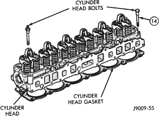
INSTALLATION
The engine cylinder head gasket is a composition gasket. The gasket is to be installed DRY. DO NOT use a gasket sealing compound on the gasket.
If the engine cylinder head is to be replaced and the original valves used, measure the valve stem diameter. Only standard size valves can be used with a service replacement engine cylinder head unless the replacement head valve stem guide bores are reamed to accommodate oversize valve stems. Remove all carbon buildup and reface the valves.
(1) Remove the shop towels from the cylinder bores. Coat the bores with clean engine oil.
(2) Position the engine cylinder head gasket (with the numbers facing up) onto the cylinder block.
CAUTION: Engine cylinder head bolts should be reused only once. Replace the head bolts if they were used before or if they have a paint dab on the top of the bolt.
(3) With bolt No.14 held in place (tape around bolt), install the engine cylinder head. Remove the tape from bolt No.14.
(4) Coat the threads of stud bolt No.11 with Loctite 592 sealant, or equivalent.
(5) Tighten the engine cylinder head bolts in sequence according to the following procedure (Fig. 33).
CAUTION: During the final tightening sequence, bolt No.11 will be tightened to a lower torque than the rest of the bolts. DO NOT overtighten bolt No.11.
(a) Tighten all bolts in sequence (1 through 14) to 30 N·m (22 ft. lbs.) torque.
(b) Tighten all bolts in sequence (1 through 14) to 61 N·m (45 ft. lbs.) torque.
(c) Check all bolts to verify they are set to 61 N·m (45 ft. lbs.) torque.
(d) Tighten bolts (in sequence): • Bolts 1 through 10 to 149 N·m (110 ft. lbs.) torque. • Bolt 11 to 13 N·m (100 ft. lbs.) torque. • Bolts 12 through 14 to 149 N·m (110 ft. lbs.) torque.
(e) Check all bolts in sequence to verify the correct torque.
(f) If not already done, clean and mark each bolt with a dab of paint after tightening. Should you encounter bolts which were painted in an earlier service operation, replace them.

Sequence
(6) Install the ignition coil and bracket assembly. (7) Connect the temperature sending unit wire connector.
(8) Install the spark plugs and tighten to 37 N·m (27 ft. lbs.) torque. Connect the ignition wires.
(9) Install the intake and engine exhaust manifolds (refer to Group 11, Exhaust System and Intake Manifold for the proper procedures).
(10) Install the fuel lines and the vacuum advance hose.
(11) If equipped, attach the power steering pump and bracket.
(12) Install the push rods, rocker arms, pivots and bridges in the order they were removed (refer to Rocker Arms and Push Rods in this section).
(13) Install the engine cylinder head cover. (14) Attach the air conditioner compressor mounting bracket to the engine cylinder head and block. Tighten the bolts to 40 N·m (30 ft. lbs.) torque.
(15) Attach the air conditioning compressor to the bracket. Tighten the bolts to 27 N·m (20 ft. lbs.) torque.
CAUTION: The serpentine drive belt must be routed correctly. Incorrect routing can cause the water pump to turn in the opposite direction causing the engine to overheat.
(16) Install the serpentine drive belt and correctly tension the belt (refer to Group 7, Cooling System for the proper procedure).
(17) Install the air cleaner and ducting. (18) Install the engine cylinder head cover. (19) Connect the hoses to the engine thermostat housing and fill the cooling system to the specified level (refer to Group 7, Cooling Systems for the proper procedure).
(20) The automatic transmission throttle linkage and cable must be adjusted after completing the engine cylinder head installation (refer to Group 21, Transmissions for the proper procedures).
(21) Install the temperature sending unit and connect the wire connector.
(22) Connect the fuel line. (23) Connect negative cable to battery. (24) Connect the upper radiator hose and heater hose at the engine thermostat housing.
(25) Fill the cooling system. Check for leaks.
WARNING: USE EXTREME CAUTION WHEN THE ENGINE IS OPERATING. DO NOT STAND IN DIRECT LINE WITH THE FAN. DO NOT PUT HANDS NEAR THE PULLEYS, BELTS OR FAN. DO NOT WEAR LOOSE CLOTHING.
(26) Operate the engine with the radiator cap off. Inspect for leaks and continue operating the engine until the engine thermostat opens. Add coolant, if required.
VALVES AND VALVE SPRINGS
This procedure is done with the engine cylinder head removed from the block.
REMOVAL
(1) Remove the engine cylinder head from the cylinder block.
(2) Use Valve Spring Compressor Tool MD-998772A and compress each valve spring.
(3) Remove the valve locks, retainers, springs and valve stem oil seals. Discard the oil seals.
(4) Use a smooth stone or a jewelers file to remove any burrs on the top of the valve stem, especially around the groove for the locks.
(5) Remove the valves, and place them in a rack in the same order as removed.
INSTALLATION
(1) Thoroughly clean the valve stems and the valve guide bores.
(2) Lightly lubricate the stem. (3) Install the valve in the original valve guide bore.
(4) Install the replacement valve stem oil seals on the valve stems. If the 0.381 mm (0.015 inch) oversize valve stems are used, oversize oil seals are required.
(5) Position the valve spring and retainer on the engine cylinder head and compress the valve spring with Valve Spring Compressor Tool MD-998772A.
(6) Install the valve locks and release the tool. (7) Tap the valve spring from side to side with a hammer to ensure that the spring is properly seated at the engine cylinder head. Also tap the top of the retainer to seat the valve locks.
(8) Install the engine cylinder head.
HYDRAULIC TAPPETS
Retain all the components in the same order as removed.
REMOVAL
(1) Remove the engine cylinder head cover. (2) Remove the bridge and pivot assemblies and rocker arms by removing the capscrews at each bridge. Alternately loosen each capscrew, one turn at a time, to avoid damaging the bridges.
(3) Remove the push rods.
(4) Remove the tappets through the push rod openings in the cylinder block with a Hydraulic Valve Tappet Removal/Installation Tool (Fig. 34).
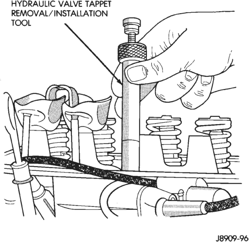
Installation Tool
INSTALLATION
It is not necessary to charge the tappets with engine oil. They will charge themselves within a very short period of engine operation.
(1) Dip each tappet in Mopar Engine Oil Supplement, or equivalent.
(2) Use Hydraulic Valve Tappet Removal/Installation Tool to install each tappet in the same bore from where it was originally removed.
(3) Install the push rods in their original locations. (4) Install the rocker arms and bridge and pivot assemblies at their original locations. Loosely install the capscrews at each bridge.
(5) Tighten the capscrews alternately, one turn at a time, to avoid damaging the bridges. Tighten the capscrews to 28 N·m (21 ft. lbs.) torque.
(6) Pour the remaining Mopar Engine Oil Supplement, or equivalent over the entire valve actuating assembly. The Mopar Engine Oil Supplement, or equivalent must remain with the engine oil for at least 1 609 km (1,000 miles). The oil supplement need not be drained until the next scheduled oil change.
(7) Install the engine cylinder head cover.
VIBRATION DAMPER
REMOVAL
(1) Disconnect negative cable from battery.
(2) Remove the serpentine drive belt and fan shroud.
(3) Remove the vibration damper retaining bolt and washer.
(4) Use Vibration Damper Removal Tool 7697 to remove the damper from the crankshaft (Fig. 35).
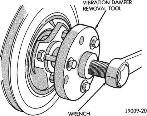
INSTALLATION
(1) Apply Mopar Silicone Rubber Adhesive Sealant to the keyway in the crankshaft and insert the key. With the key in position, align the keyway on the vibration damper hub with the crankshaft key and tap the damper onto the crankshaft.
(2) Install the vibration damper retaining bolt and washer.
(3) Tighten the damper retaining bolt to 108 N·m (80 ft. lbs.) torque.
(4) Install the serpentine drive belt and tighten to the specified tension (refer to Group 7, Cooling Systems for the proper specifications and procedures).
(5) Connect negative cable to battery.
TIMING CASE COVER
REMOVAL
(1) Disconnect negative cable from battery. (2) Remove the vibration damper. (3) Remove the fan and hub assembly and remove the fan shroud.
(4) Remove the accessory drive brackets that are attached to the timing case cover.
(5) Remove the A/C compressor (if equipped) and generator bracket assembly from the engine cylinder head and move to one side.
(6) Remove the oil pan-to-timing case cover bolts and timing case cover-to-cylinder block bolts.
(7) Remove the timing case cover and gasket from the engine. Make sure the tension spring and thrust pin do not fall out of the preload bolt.
(8) Pry the crankshaft oil seal from the front of the timing case cover (Fig. 36).
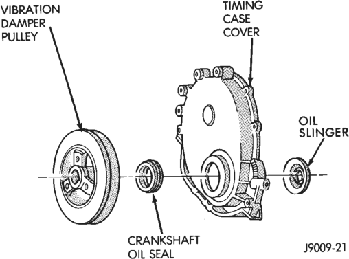
INSTALLATION
Clean the timing case cover, oil pan and cylinder block gasket surfaces.
(1) Install a new crankshaft oil seal in the timing case cover. The open end of the seal should be toward the inside of the cover. Support the cover at the seal area while installing the seal. Force it into position with Seal Installation Tool 6139.
(2) Position the gasket on the cylinder block. (3) Position the timing case cover on the oil pan gasket and the cylinder block. Make sure the tension spring and thrust pin are in place in the camshaft preload bolt.
(4) Insert Timing Case Cover Alignment and Seal Installation Tool 6139 in the crankshaft opening in the cover (Fig. 37).
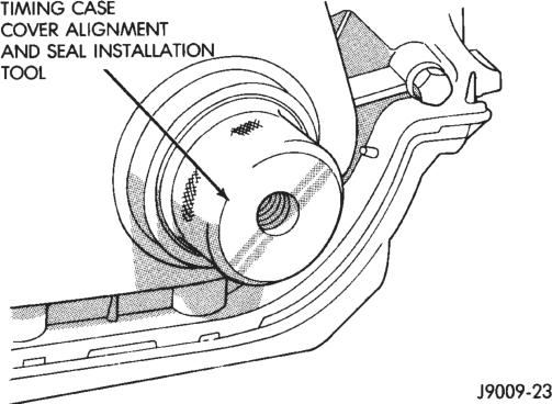
Installation Tool 6139
(5) Install the timing case cover-to-cylinder block and the oil pan-to-timing case cover bolts.
(6) Tighten the 1/4 inch cover-to-block bolts to 7 N·m (60 in. lbs.) torque. Tighten the 5/16 inch front cover-to-block bolts to 22 N·m (192 in. lbs.) torque. Tighten the oil pan-to-cover 1/4 inch bolts to 14 N·m (120 in. lbs.) torque. Tighten the oil pan-to-cover 5/16 inch bolts to 18 N·m (156 in. lbs.) torque.
(7) Remove the cover alignment tool. (8) Apply a light film of engine oil on the vibration damper hub contact surface of the seal.
(9) Apply Mopar Silicone Rubber Adhesive Sealant to the keyway in the crankshaft and insert the key. With the key inserted in the keyway in the crankshaft, install the vibration damper, washer and bolt. Lubricate and tighten the bolt to 108 N·m (80 ft. lbs.) torque.
(10) Install the A/C compressor (if equipped) and generator bracket assembly.
(11) Install the engine fan and hub assembly and shroud.
(12) Install the serpentine drive belt and tighten to obtain the specified tension.
(13) Connect negative cable to battery.
TIMING CHAIN AND SPROCKETS
REMOVAL
(1) Disconnect negative cable from battery. (2) Remove the fan and shroud. (3) Remove the serpentine drive belt. (4) Remove the crankshaft vibration damper. (5) Remove the timing case cover. (6) Rotate crankshaft until the “0” timing mark is closest to and on the center line with camshaft sprocket timing mark (Fig. 38).
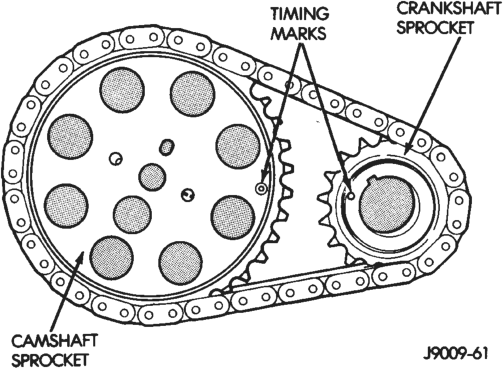
(7) Remove the oil slinger from the crankshaft. (8) Remove the tension spring and thrust pin from the preload bolt (Fig. 39). Remove the camshaft sprocket retaining preload bolt and washer.
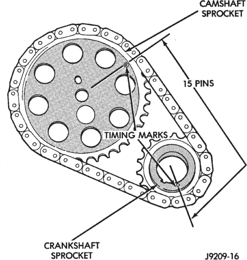
(9) Remove the crankshaft sprocket, camshaft sprocket and timing chain as an assembly.
(10) Installation of the timing chain with the timing marks on the crankshaft and camshaft sprockets properly aligned ensures correct valve timing. A worn or stretched timing chain will adversely affect valve timing. If the timing chain deflects more than 12.7 mm (1/2 inch) replace it. The correct timing chain has 48 pins. A chain with more than 48 pins will cause excessive slack.
INSTALLATION
Assemble the timing chain, crankshaft sprocket and camshaft sprocket with the timing marks aligned (Fig. 40).
(1) Apply Mopar Silicone Rubber Adhesive Sealant to the keyway in the crankshaft and insert the key. With the key in the keyway on the crankshaft, install the assembly on the crankshaft and camshaft.
(2) Install the camshaft sprocket retaining preload bolt and washer (Fig. 39). Tighten the preload bolt to 108 N·m (80 ft. lbs.) torque. (3) To verify correct installation of the timing chain, turn the crankshaft to position the camshaft sprocket timing mark as shown in (Fig. 40). Count the number of chain pins between the timing marks of both sprockets. There must be 15 pins.
(4) Install the crankshaft oil slinger. (5) Replace the oil seal in the timing case cover. (6) Lubricate the tension spring, thrust pin and pin bore in the preload bolt with Mopar Engine Oil Supplement, or equivalent. Install the spring and thrust pin in the preload bolt head (Fig. 39).
(7) Install the timing case cover and gasket. (8) With the key installed in the crankshaft keyway, install the vibration damper, washer and bolt. Lubricate and tighten the bolt to 108 N·m (80 ft. lbs.) torque.
(9) Install the serpentine drive belt and tighten to the specified tension (refer to Group 7, Cooling System for the proper procedure).
(10) Install the fan and hub assembly. Install the shroud.
(11) Connect negative cable to battery.
CAMSHAFT
REMOVAL
WARNING: THE COOLANT IN A RECENTLY OPER- ATED ENGINE IS HOT AND PRESSURIZED. RELEASE THE PRESSURE BEFORE REMOVING THE DRAIN COCK, CAP AND DRAIN PLUGS.
(1) Disconnect negative cable from battery. (2) Drain the cooling system. DO NOT waste reusable coolant. If the solution is clean, drain it into a clean container for reuse.
(3) Remove the radiator or radiator and condenser, if equipped with A/C (refer to Group 7, Cooling System for the proper procedure).
(4) Remove the air conditioner condenser and receiver/drier assembly as a charged unit, if equipped (refer to Group 24, Heating and Air Conditioning).
(5) Remove the distributor cap and mark the position of the rotor.
(6) Remove the distributor and ignition wires. (7) Remove the engine cylinder head cover. (8) Remove the rocker arms, bridges and pivots. (9) Remove the push rods. (10) Remove the engine cylinder head and gasket.
(11) Remove the hydraulic valve tappets from the engine cylinder head.
(12) Remove the vibration damper. (13) Remove the timing case cover. (14) Remove the timing chain and sprockets. (15) Remove the front bumper and/or grille, as required.
(16) Remove the camshaft (Fig. 41).
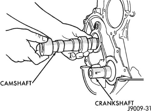
INSTALLATION
(1) Inspect the cam lobes for wear. (2) Inspect the bearing journals for uneven wear pattern or finish.
(3) Inspect the bearings for wear. (4) Inspect the distributor drive gear for wear. (5) If the camshaft appears to have been rubbing against the timing case cover, examine the oil pressure relief holes in the rear cam journal. The oil pressure relief holes must be free of debris.
(6) Lubricate the camshaft with Mopar Engine Oil Supplement, or equivalent.
(7) Carefully install the camshaft to prevent damage to the camshaft bearings (Fig. 41).
(8) Install the timing chain, crankshaft sprocket and camshaft sprocket with the timing marks aligned.
(9) Install the camshaft sprocket retaining preload bolt. Tighten the bolt to 108 N·m (80 ft. lbs.) torque.
(10) Lubricate the tension spring, the thrust pin and the pin bore in the preload bolt with Mopar Engine Oil Supplement, or equivalent. Install the spring and thrust pin in the preload bolt head.
(11) Install the timing case cover with a replacement oil seal (Fig. 42). Refer to Timing Case Cover Installation.
(12) Install the vibration damper (Fig. 42). (13) Install the hydraulic valve tappets. (14) Install the engine cylinder head. (15) Install the push rods.
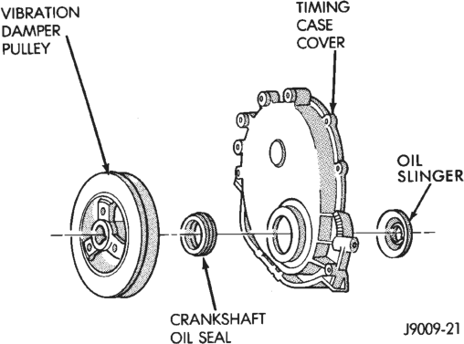
(16) Install the rocker arms and pivot and bridge assemblies. Tighten each of the capscrews for each bridge alternately, one turn at a time, to avoid damaging the bridge.
(17) Install the engine cylinder head cover. (18) Position the oil pump gear. Refer to Distributor in the Component Removal/Installation section of Group 8D, Ignition Systems.
(19) Install the distributor and ignition wires. Refer to Distributor in the Component Removal/Installation section of Group 8D, Ignition Systems.
(20) Install the serpentine drive belt and tighten to the specified tension (refer to Group 7, Cooling System for the proper procedure).
NOTE: During installation, lubricate the hydraulic valve tappets and all valve components with Mopar Engine Oil Supplement, or equivalent. The Mopar Engine Oil Supplement, or equivalent must remain with the engine oil for at least 1 609 km (1,000 miles). The oil supplement need not be drained until the next scheduled oil change.
(21) Install the A/C condenser and receiver/drier assembly, if equipped (refer to Group 24, Heating and Air Conditioning).
CAUTION: Both service valves must be opened before the air conditioning system is operated.
(22) Install the radiator, connect the hoses and fill the cooling system to the specified level (refer to Group 7, Cooling System for the proper procedure).
(23) Check the ignition timing and adjust as necessary.
(24) Install the grille and bumper, if removed. (25) Connect negative cable to battery.
CAMSHAFT PIN REPLACEMENT
REMOVAL
WARNING: DO NOT LOOSEN THE RADIATOR DRAIN COCK WITH THE SYSTEM HOT AND PRES- SURIZED BECAUSE SERIOUS BURNS FROM COOL- ANT CAN OCCUR.
(1) Disconnect negative cable from battery. (2) Drain the radiator. DO NOT waste reusable coolant. Drain the coolant into a clean container.
(3) Remove the fan and shroud. (4) Disconnect the radiator overflow tube, radiator hoses, automatic transmission fluid cooler pipes (if equipped).
(5) Remove the radiator. (6) If equipped with air conditioning:
CAUTION: DO NOT loosen or disconnect any air conditioner system fittings. Move the condenser and receiver/drier aside as a complete assembly.
(a) Remove the A/C compressor serpentine drive belt idler pulley.
(b) Disconnect and remove the generator. (c) Remove the A/C condenser attaching bolts and move the condenser and receiver/drier assembly up and out of the way. (7) Remove the serpentine drive belt. (8) Remove the crankshaft vibration damper. (9) Remove the timing case cover. Clean the gasket material from the cover.
(10) Remove the thrust pin and tension spring from the preload bolt head.
(11) Rotate crankshaft until the crankshaft sprocket timing mark is closest to and on the center line with the camshaft sprocket timing mark (Fig. 43).
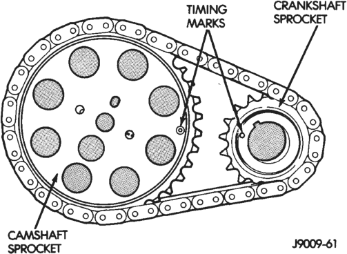
(12) Remove the camshaft sprocket preload retaining bolt and washer.
(13) Remove the crankshaft oil slinger. (14) Remove the sprockets and chain as an assembly.
CAUTION: The following procedural step must be accomplished to prevent the camshaft from damaging the rear camshaft plug during pin installation.
(15) Inspect the damaged camshaft pin. (16) If the pin is a spring-type pin, remove the broken pin by inserting a self-tapping screw into the pin and carefully pulling the pin from the camshaft.
(17) If the pin is a dowel-type pin, center-punch it. Ensure the exact center is located when centerpunching the pin.
CAUTION: Cover the opened oil pan area to prevent metal chips from entering the pan.
(18) Drill into the pin center with a 4 mm (5/32 inch) drill bit.
(19) Insert a self-tapping screw into the drilled pin and carefully pull the pin from the camshaft.
CAMSHAFT BEARINGS
The camshaft rotates within four steel-shelled, babbitt-lined bearings that are pressed into the cylinder block and then line reamed. The camshaft bearing bores and bearing diameters are not the same size. They are stepped down in 0.254 mm (0.010 inch) increments from the front bearing (largest) to the rear bearing (smallest). This permits easier removal and installation of the camshaft. The camshaft bearings are pressure lubricated.
NOTE: It is not advisable to attempt to replace camshaft bearings unless special removal and installation tools are available.
Camshaft end play is maintained by the load placed on the camshaft by the sprocket preload bolt tension spring and thrust pin.
INSTALLATION
(1) Clean the camshaft pin hole. (2) Compress the center of the replacement spring pin with vise grips.
(3) Carefully drive the pin into the camshaft pin hole until it is seated.
(4) Install the camshaft sprocket, crankshaft sprocket and timing chain with the timing marks aligned (Fig. 43).
(5) To verify correct installation of the timing chain, turn the crankshaft to position the camshaft sprocket timing mark as shown in (Fig. 44). Count the number of chain pins between the timing marks of both sprockets. There must be 15 pins.
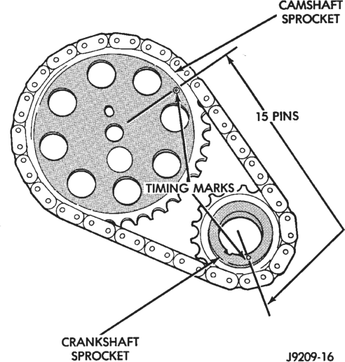
Typical
(6) Install the crankshaft oil slinger. (7) Tighten the camshaft sprocket preload bolt to 108 N·m (80 ft. lbs.) torque. (8) Check the valve timing. (9) Lubricate the tension spring, the thrust pin and the pin bore in the preload bolt with Mopar Engine Oil Supplement, or equivalent. Install the spring and thrust pin in the preload bolt head.
(10) Coat both sides of the replacement timing case cover gasket with gasket sealer. Apply a 3 mm (1/8 inch) bead of Mopar Silicone Rubber Adhesive Sealant, or equivalent to the joint formed at the oil pan and cylinder block.
(11) Position the timing case cover on the oil pan gasket and the cylinder block.
(12) Place Timing Case Cover Alignment and Seal Installation Tool 6139 in the crankshaft opening in the cover (Fig. 45).
(13) Install the timing case cover-to-cylinder block bolts. Install the oil pan-to-timing case cover bolts.
(14) Tighten the 1/4 inch cover-to-block bolts to 7 N·m (60 in. lbs.) torque. Tighten the 5/16 inch front cover-to-block bolts to 22 N·m (192 in. lbs.) torque. Tighten the oil pan-to-cover 1/4 inch bolts to 14 N·m (120 in. lbs.) torque. Tighten the oil pan-to-cover 5/16 inch bolts to 18 N·m (156 in. lbs.) torque.
(15) Remove the cover alignment tool and install a replacement oil seal into the cover.
(16) Install the vibration damper on the crankshaft.
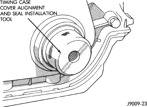
Installation Tool 6139
(17) Lubricate and tighten the damper bolt to 108 N·m (80 ft. lbs.) torque.
(18) If equipped with air conditioning:
(a) Install the A/C compressor serpentine drive belt idler pulley.
(b) Install the generator. (c) Install the A/C condenser and receiver/drier assembly. (19) Install the serpentine drive belt on the pulleys and tighten (refer to Group 7, Cooling System for the specifications and procedures).
(20) Install the radiator. Connect the radiator hoses and automatic transmission fluid cooler pipes, if equipped. Fill the cooling system.
(21) Install the fan and shroud. (22) Connect negative cable to battery.
CRANKSHAFT MAIN BEARINGS
REMOVAL
(1) Disconnect negative cable from battery. (2) Remove the spark plugs. (3) Raise the vehicle. (4) Remove the oil pan and oil pump. (5) Remove only one main bearing cap and lower insert at a time (Fig. 46).
(6) Remove the lower insert from the bearing cap. (7) Remove the upper insert by LOOSENING (DO NOT REMOVE) all of the other bearing caps. Now insert a small cotter pin tool in the crankshaft journal oil hole. Bend the cotter pin as illustrated to fabricate the tool (Fig. 47). With the cotter pin tool in place, rotate the crankshaft so that the upper bearing insert will rotate in the direction of its locking tab. Because there is no hole in the No.3 main journal, use a tongue depressor or similar soft-faced tool to remove the bearing insert (Fig. 47). After moving
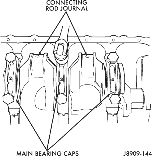
Inserts the insert approximately 25 mm (1 inch), it can be removed by applying pressure under the tab.
(8) Using the same procedure described above, remove the remaining bearing inserts one at a time for inspection.
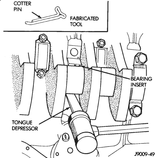
INSTALLATION
(1) Lubricate the bearing surface of each insert with engine oil.
(2) Loosen all the main bearing caps. Install the main bearing upper inserts.
(3) Install the lower bearing inserts into the main bearing caps.
(4) Install the main bearing cap(s) and lower insert(s).
(5) Tighten the bolts of caps 1, 2, 4, 5, 6, and 7 to 54 N·m (40 ft. lbs.) torque. Now tighten these bolts to 95 N·m (70 ft. lbs.) torque. Finally, tighten these bolts to 108 N·m (80 ft. lbs.) torque.
(6) Push the crankshaft forward and backward. Load the crankshaft front or rear and tighten cap bolt No.3 to 54 N·m (40 ft. lbs.) torque. Then tighten to 95 N·m (70 ft. lbs.) torque and finally tighten to 108 N·m (80 ft. lbs.) torque. (7) Rotate the crankshaft after tightening each main bearing cap to ensure the crankshaft rotates freely.
(8) Check crankshaft end play. Crankshaft end play is controlled by the thrust bearing which is flange and installed at the No.2 main bearing position.
(a) Attach a magnetic base dial indicator to the cylinder block at either the front or rear of the engine.
(b) Position the dial indicator rod so that it is parallel to the center line of the crankshaft.
(c) Pry the crankshaft forward, position the dial indicator to zero.
(d) Pry the crankshaft forward and backward. Note the dial indicator readings. End play is the difference between the high and low measurements (Fig. 48). Correct end play is 0.038-0.165 mm (0.0015-0.0065 inch). The desired specifications are 0.051-0.064 mm (0.002-0.0025 inch). (e) If end play is not within specification, inspect crankshaft thrust faces for wear. If no wear is apparent, replace the thrust bearing and measure end play. If end play is still not within specification, replace the crankshaft.
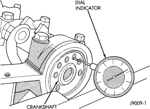
(9) If the crankshaft was removed, install the crankshaft into the cylinder block (refer to Cylinder Block - Assemble).
(10) Install the oil pan. (11) Install the drain plug. Tighten the plug to 34 N·m (25 ft. lbs.) torque.
(12) Lower the vehicle. (13) Install the spark plugs. Tighten the plugs to 37 N·m (27 ft. lbs.) torque. (14) Fill the oil pan with engine oil to the full mark on the dipstick level.
(15) Connect negative cable to battery.
OIL PAN
REMOVAL
(1) Disconnect negative cable from battery. (2) Raise the vehicle. (3) Remove the oil pan drain plug and drain the engine oil.
(4) Disconnect the exhaust pipe at the exhaust manifold.
(5) Disconnect the exhaust hanger at the catalytic converter and lower the pipe.
(6) Remove the starter motor. (7) Remove the engine flywheel and transmission torque converter housing access cover.
(8) If equipped with an oil level sensor, disconnect the sensor.
(9) Position a jack stand directly under the engine vibration damper.
(10) Place a piece of wood (2 x 2) between the jack stand and the engine vibration damper.
(11) Remove the engine mount through bolts. (12) Using the jack stand, raise the engine until adequate clearance is obtained to remove the oil pan.
(13) Remove the oil pan bolts. Carefully slide the oil pan and gasket to the rear. If equipped with an oil level sensor, take care not to damage the sensor.
INSTALLATION
(1) Clean the block and pan gasket surfaces. (2) Fabricate 4 alignment dowels from 1 1/2 x 1/4 inch bolts. Cut the head off the bolts and cut a slot into the top of the dowel. This will allow easier installation and removal with a screwdriver (Fig. 49).
(3) Install two dowels in the timing case cover. Install the other two dowels in the cylinder block (Fig. 50).
(4) Slide the one-piece gasket over the dowels and onto the block and timing case cover.
(5) Position the oil pan over the dowels and onto the gasket. If equipped with an oil level sensor, take care not to damage the sensor.
(6) Install the 1/4 inch oil pan bolts. Tighten these bolts to 14 N·m (120 in. lbs.) torque. Install the 5/16
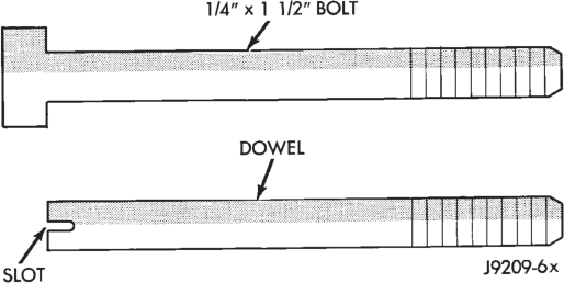
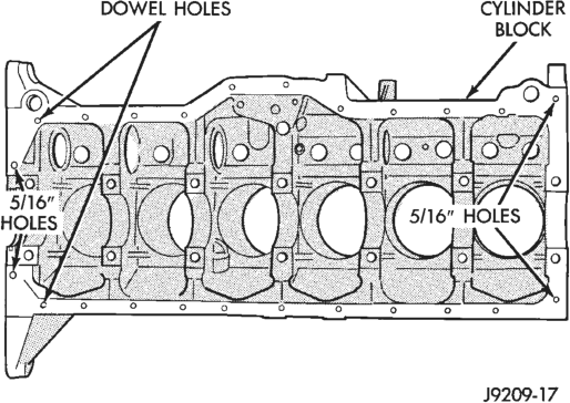
inch oil pan bolts (Fig. 51). Tighten these bolts to 18 N·m (156 in. lbs.) torque.
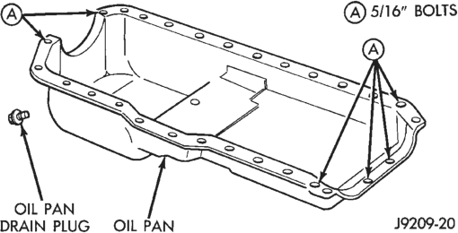
(7) Remove the dowels. Install the remaining 1/4 inch oil pan bolts. Tighten these bolts to 14 N·m (120 in. lbs.) torque.
(8) Lower the engine until it is properly located on the engine mounts.
(9) Install the through bolts and tighten the nuts.
(10) Lower the jack stand and remove the piece of wood.
(11) Install the engine flywheel and transmission torque converter housing access cover.
(12) Install the engine starter motor. (13) Connect the exhaust pipe to the hanger and to the engine exhaust manifold.
(14) Install the oil pan drain plug (Fig. 51). Tighten the plug to 34 N·m (25 ft. lbs.) torque.
(15) Lower the vehicle. (16) Connect negative cable to battery. (17) Fill the oil pan with engine oil to the specified level.
WARNING: USE EXTREME CAUTION WHEN THE ENGINE IS OPERATING. DO NOT STAND IN A DIRECT LINE WITH THE FAN. DO NOT PUT YOUR HANDS NEAR THE PULLEYS, BELTS OR FAN. DO NOT WEAR LOOSE CLOTHING.
(18) Start the engine and inspect for leaks.
PISTONS AND CONNECTING RODS
REMOVAL
(1) Remove the engine cylinder head cover. (2) Remove the rocker arms, bridges and pivots. (3) Remove the push rods. (4) Remove the engine cylinder head. (5) Position the pistons one at a time near the bottom of the stroke. Use a ridge reamer to remove the ridge from the top end of the cylinder walls. Use a protective cloth to collect the cuttings.
(6) Raise the vehicle. (7) Drain the engine oil. (8) Remove the oil pan and gasket. (9) Remove the connecting rod bearing caps and inserts. Mark the caps and rods with the cylinder bore location. The connecting rods and caps are stamped with a two letter combination (Fig. 52).
(10) Lower the vehicle until it is about 2 feet from the floor.
CAUTION: Ensure that the connecting rod bolts DO NOT scratch the crankshaft journals or cylinder walls. Short pieces of rubber hose, slipped over the rod bolts will provide protection during removal.
(11) Have an assistant push the piston and connecting rod assemblies up and through the top of the cylinder bores (Fig. 53).
INSTALLATION
(1) Clean the cylinder bores thoroughly. Apply a light film of clean engine oil to the bores with a clean lint-free cloth.
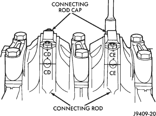
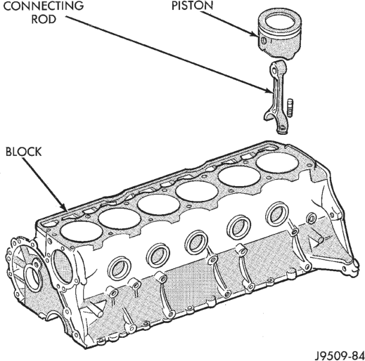
Assembly
(2) Install the piston rings on the pistons if removed.
(3) Lubricate the piston and rings with clean engine oil.
CAUTION: Ensure that connecting rod bolts DO NOT scratch the crankshaft journals or cylinder walls. Short pieces of rubber hose slipped over the connecting rod bolts will provide protection during installation.
(4) Use a piston ring compressor to install the connecting rod and piston assemblies through the top of the cylinder bores (Fig. 54).
(5) Ensure the arrow on the piston top points to the front of the engine (Fig. 54).
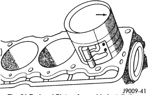
(6) Raise the vehicle. (7) Each bearing insert is fitted to its respective journal to obtain the specified clearance between the bearing and the journal. In production, the select fit is obtained by using various-sized, color-coded bearing inserts as listed in the Connecting Rod Bearing Fitting Chart. The color code appears on the edge of the bearing insert. The size is not stamped on inserts used for production of engines.
(8) The rod journal is identified during the engine production by a color-coded paint mark on the adjacent cheek or counterweight toward the flange (rear) end of the crankshaft. The color codes used to indicate journal sizes are listed in the Connecting Rod Bearing Fitting Chart.
(9) When required, upper and lower bearing inserts of different sizes may be used as a pair (refer to Connecting Rod Bearing Fitting Chart). A standard size insert is sometimes used in combination with a 0.025 mm (0.001 inch) undersize insert to reduce clearance 0.013 mm (0.0005 inch).
CAUTION: DO NOT intermix bearing caps. Each connecting rod and bearing cap are stamped with the cylinder number. The stamp is located on a machined surface adjacent to the oil squirt hole that faces the camshaft side of the cylinder block.
(10) Install the connecting rod bearing caps and inserts in the same positions as removed.
CAUTION: Verify that the oil squirt holes in the rods face the camshaft and that the arrows on the pistons face the front of the engine.
(11) Install the oil pan and gaskets as outlined in the installation procedure.
(12) Lower the vehicle. (13) Install the engine cylinder head, push rods, rocker arms, bridges, pivots and engine cylinder head cover.
(14) Fill the crankcase with engine oil.
REAR MAIN OIL SEALS
The crankshaft rear main bearing oil seal consists of two half pieces of viton with a single lip that effectively seals the rear of the crankshaft. Replace the upper and lower seal halves as a unit to ensure leakfree operation.
REMOVAL
(1) Remove the engine flywheel or converter drive plate.
(2) Remove the oil pan. (3) Remove the rear main bearing cap (No.7). (4) Push the upper seal out of the groove. Ensure that the crankshaft and seal groove are not damaged.
(5) Remove the lower half of the seal from the bearing cap.
INSTALLATION
(1) Wipe the seal surface area of the crankshaft until it is clean.
(2) Apply a thin coat of engine oil. (3) Coat the lip of the seal with engine oil. (4) Carefully position the upper seal into the groove in the cylinder block. The lip of the seal faces toward the front of the engine.
(5) Place the lower half of the seal into bearing cap No.7 (Fig. 55).
(6) Coat the outer curved surface of the lower seal with soap and the lip of the seal with engine oil (Fig. 55).
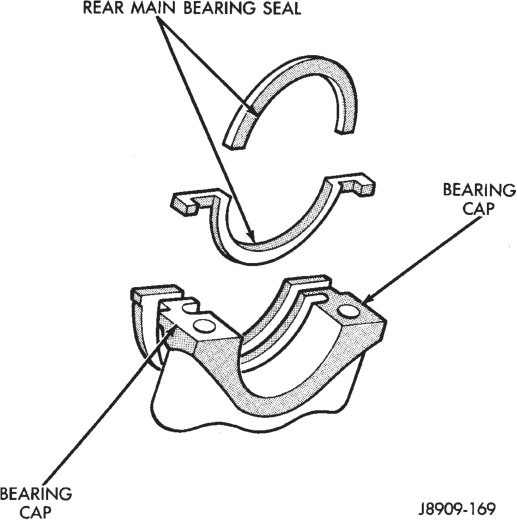
(7) Position the lower seal into the bearing cap recess and seat it firmly. Be sure the seal is flush with the cylinder block pan rail.
(8) Apply Loctite 518, or equivalent on the rear bearing cap (Fig. 56). The bead should be 3 mm (0.125 in) thick. DO NOT apply Loctite 518, or equivalent to the lip of the seal.
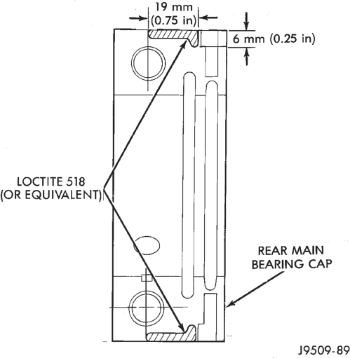
(9) Install the rear main bearing cap. DO NOT strike the cap more than twice for proper engagement.
(10) Tighten all main bearing bolts to 108 N·m (80 ft. lbs.) torque.
(11) Install the oil pan gasket and oil pan. (12) Install the engine flywheel or converter drive plate.
OIL PUMP
A gear-type oil pump is mounted at the underside of the cylinder block opposite the No.4 main bearing.
The pump incorporates a nonadjustable pressure relief valve to limit maximum pressure to 517 kPa (75 psi). In the relief position, the valve permits oil to bypass through a passage in the pump body to the inlet side of the pump.
Oil pump removal or replacement will not affect the distributor timing because the distributor drive gear remains in mesh with the camshaft gear.
REMOVAL
(1) Drain the engine oil. (2) Remove the oil pan.
(3) Remove the pump-to-cylinder block attaching bolts. Remove the pump assembly with gasket (Fig. 57).
CAUTION: If the oil pump is not to be serviced, DO NOT disturb position of oil inlet tube and strainer assembly in pump body. If the tube is moved within the pump body, a replacement tube and strainer assembly must be installed to assure an airtight seal.
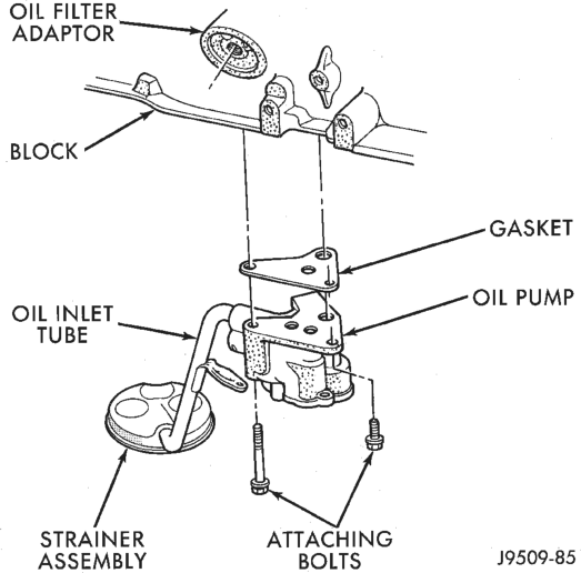
INSTALLATION
(1) Install the oil pump on the cylinder block using a replacement gasket. Tighten the bolts to 23 N·m (17 ft. lbs.) torque.
(2) Install the oil pan. (3) Fill the oil pan with oil to the specified level.
TIMING CASE COVER OIL SEAL
This procedure is done with the timing case cover installed.
REMOVAL
(1) Disconnect negative cable from battery. (2) Remove the serpentine drive belt. (3) Remove the vibration damper. (4) Remove the radiator shroud. (5) Carefully remove the oil seal. Make sure seal bore is clean.
INSTALLATION
(1) Position the replacement oil seal on Timing Case Cover Alignment and Seal Installation Tool 6139 with seal open end facing inward. Apply a light film of Perfect Seal, or equivalent, on the outside diameter of the seal. Lightly coat the crankshaft with engine oil.
(2) Position the tool and seal over the end of the crankshaft and insert a draw screw tool into Seal Installation Tool 6139 (Fig. 58). Tighten the nut against the tool until it contacts the cover.
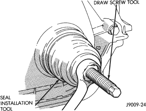
(3) Remove the tools. Apply a light film of engine oil on the vibration damper hub contact surface of the seal.
(4) Apply Mopar Silicone Rubber Adhesive Sealant to the keyway in the crankshaft and insert the key. With the key inserted in the keyway in the crankshaft, install the vibration damper, washer and bolt. Lubricate and tighten the bolt to 108 N·m (80 ft. lbs.) torque.
(5) Install the serpentine belt and tighten to the specified tension (refer to Group 7, Cooling Systems for the proper specifications and procedures).
(6) Install the radiator shroud. (7) Connect negative cable to battery.
DISASSEMBLY AND ASSEMBLY
VALVE SERVICE
Clean all carbon deposits from the combustion chambers, valve ports, valve stems, valve stem guides and head.
Clean all grime and gasket material from the engine cylinder head machined gasket surface.
Inspect for cracks in the combustion chambers and valve ports.
Inspect for cracks on the exhaust seat. Inspect for cracks in the gasket surface at each coolant passage.
Inspect valves for burned, cracked or warped heads.
Inspect for scuffed or bent valve stems. Replace valves displaying any damage.
VALVE REFACING
(1) Use a valve refacing machine to reface the intake and exhaust valves to the specified angle.
(2) After refacing, a margin of at least 0.787 mm (0.031 inch) must remain (Fig. 59). If the margin is less than 0.787 mm (0.031 inch), the valve must be replaced.
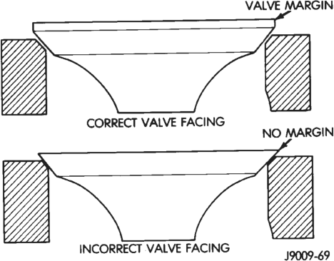
VALVE SEAT REFACING
(1) Install a pilot of the correct size in the valve guide bore. Reface the valve seat to the specified angle with a good dressing stone. Remove only enough metal to provide a smooth finish.
(2) Use tapered stones to obtain the specified seat width when required.
(3) Control valve seat runout to a maximum of 0.0635 mm (0.0025 in.) (Fig. 60).
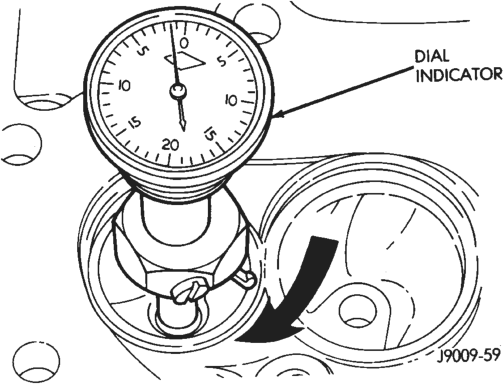
VALVE STEM OIL SEAL REPLACEMENT
Valve stem oil seals are installed on each valve stem to prevent rocker arm lubricating oil from entering the combustion chamber through the valve guide bores. One seal is marked INT (intake valve) and the other is marked EXH (exhaust valve).
Replace the oil seals whenever valve service is performed or if the seals have deteriorated.
VALVE GUIDES
The valve guides are an integral part of the engine cylinder head and are not replaceable.
When the valve stem guide clearance is excessive, the valve guide bores must be reamed oversize. Service valves with oversize stems are available in 0.076 mm (0.003 inch) and 0.381 mm (0.015 inch) increments.
Corresponding oversize valve stem seals are also available and must be used with valves having 0.381 mm (0.015 inch) oversize stems.
NOTE: If the valve guides are reamed oversize, the valve seats must be ground to ensure that the valve seat is concentric to the valve guide.
VALVE STEM-TO-GUIDE CLEARANCE MEASUREMENT
Valve stem-to-guide clearance may be measured by either of the following two methods.
PREFERRED METHOD
(1) Remove the valve from the head. (2) Clean the valve stem guide bore with solvent and a bristle brush.
(3) Insert a telescoping gauge into the valve stem guide bore approximately 9.525 mm (.375 inch) from the valve spring side of the head (Fig. 61).
(4) Remove and measure telescoping gauge with a micrometer.
(5) Repeat the measurement with contacts lengthwise to engine cylinder head.
(6) Compare the crosswise to lengthwise measurements to determine out-of-roundness. If the measurements differ by more than 0.0635 mm (0.0025 in.), ream the guide bore to accommodate an oversize valve stem.
(7) Compare the measured valve guide bore diameter with specifications (7.95-7.97 mm or 0.313-0.314 inch). If the measurement differs from specification by more than 0.076 mm (0.003 inch), ream the guide bore to accommodate an oversize valve stem.
ALTERNATIVE METHOD
(1) Use a dial indicator to measure the lateral movement of the valve stem (stem-to-guide clear-
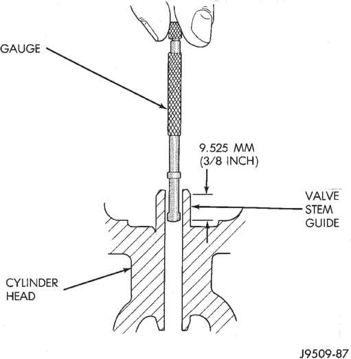
ance). This must be done with the valve installed in its guide and just off the valve seat (Fig. 62).
(2) Correct clearance is 0.025-0.0762 mm (0.001-0.003 inch). If indicated movement exceeds the specification ream the valve guide to accommodate an oversize valve stem.
NOTE: Valve seats must be ground after reaming the valve guides to ensure that the valve seat is concentric to the valve guide.
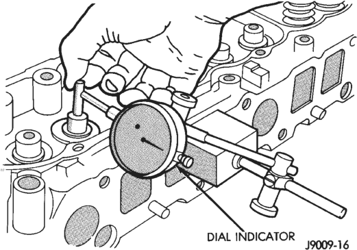
Stem
VALVE SPRING TENSION TEST
Use a universal Valve Spring Tester and a torque wrench to test each valve spring for the specified tension value (Fig. 63).
Replace valve springs that are not within specifications.
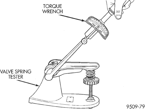
CYLINDER BLOCK
DISASSEMBLY
Refer to the applicable sections for detailed instructions.
(1) Drain the engine oil. Remove and discard the oil filter.
(2) Remove the water pump from the cylinder block.
(3) Remove the vibration damper. (4) Remove the timing case cover and lay the cover upside down.
(5) Position a drift punch into the slot in the back of the cover and tap the old seal out.
(6) Remove the oil slinger from crankshaft. (7) Remove the camshaft retaining bolt and remove the sprockets and chain as an assembly.
(8) Remove the camshaft. (9) Remove the oil pan and gasket. (10) Remove the front and rear oil galley plugs. (11) Remove the oil pump. (12) Remove the connecting rods and the pistons. Remove the connecting rod and piston assemblies through the top of the cylinder bores.
(13) Remove the crankshaft.
ASSEMBLY
Refer to the applicable sections for detailed instructions.
(1) Install the crankshaft. (2) Install the connecting rods and the pistons through the top of the cylinder bores.
(3) Install the oil pump.
(4) Install the oil pan and gasket. (5) Install the camshaft. (6) Install the sprockets and chain as an assembly. (7) Install the oil slinger from the crankshaft. (8) Install the timing case cover seal. (9) Install the timing case cover. (10) Install the vibration damper. (11) Install the water pump. Tighten the mounting bolts to 31 N·m (270 in. lbs.) torque.
(12) Lubricate the oil filter seal with clean engine oil. Tighten oil filter to 18 N·m (13 ft. lbs.) torque.
(13) Install the engine into the vehicle. (14) Fill the engine with clean lubrication oil (refer to Group 0, Lubrication and Maintenance).
(15) Fill the cooling system.
CLEANING AND INSPECTION
ENGINE CYLINDER HEAD
CLEANING
Thoroughly clean the engine cylinder head and cylinder block mating surfaces. Clean the intake and engine exhaust manifold and engine cylinder head mating surfaces. Remove all gasket material and carbon.
Check to ensure that no coolant or foreign material has fallen into the tappet bore area.
Remove the carbon deposits from the combustion chambers and top of the pistons.
INSPECTION
Use a straightedge and feeler gauge to check the flatness of the engine cylinder head and block mating surfaces.
ENGINE CYLINDER HEAD COVER
CLEANING
Remove any original sealer from the cover sealing surface of the engine cylinder head and clean the surface using a fabric cleaner.
Remove all residue from the sealing surface using a clean, dry cloth.
INSPECTION
Inspect the engine cylinder head cover for cracks. Replace the cover, if cracked.
The original dark grey gasket material should NOT be removed. If sections of the gasket material are missing or are compressed, replace the engine cylinder head cover. However, sections with minor damage such as small cracks, cuts or chips may be repaired with a hand held applicator. The new material must be smoothed over to maintain gasket height. Allow the gasket material to cure prior to engine cylinder head cover installation.
ROCKER ARMS AND PUSH RODS
CLEANING
Clean all the components with cleaning solvent. Use compressed air to blow out the oil passages in the rocker arms and push rods.
INSPECTION
Inspect the pivot surface area of each rocker arm. Replace any that are scuffed, pitted, cracked or excessively worn.
Inspect the valve stem tip contact surface of each rocker arm and replace any rocker arm that is deeply pitted.
Inspect each push rod end for excessive wear and replace as required. If any push rod is excessively worn because of lack of oil, replace it and inspect the corresponding hydraulic tappet for excessive wear.
Inspect the push rods for straightness by rolling them on a flat surface or by shining a light between the push rod and the flat surface.
A wear pattern along the length of the push rod is not normal. Inspect the engine cylinder head for obstruction if this condition exists.
HYDRAULIC TAPPETS
CLEANING
Clean each tappet assembly in cleaning solvent to remove all varnish, gum and sludge deposits.
INSPECTION
Inspect for indications of scuffing on the side and base of each tappet body.
Inspect each tappet base for concave wear with a straightedge positioned across the base. If the base is concave, the corresponding lobe on the camshaft is also worn. Replace the camshaft and defective tappets.
LEAK-DOWN TEST
After cleaning and inspection, test each tappet for specified leak-down rate tolerance to ensure zero-lash operation (Fig. 64).
Swing the weighted arm of the hydraulic valve tappet tester away from the ram of the Leak-Down Tester.
(1) Place a 7.925-7.950 mm (0.312-0.313 inch) diameter ball bearing on the plunger cap of the tappet.
(2) Lift the ram and position the tappet (with the ball bearing) inside the tester cup.
(3) Lower the ram, then adjust the nose of the ram until it contacts the ball bearing. DO NOT tighten the hex nut on the ram.
(4) Fill the tester cup with hydraulic valve tappet test oil until the tappet is completely submerged.
(5) Swing the weighted arm onto the push rod and pump the tappet plunger up and down to remove air. When the air bubbles cease, swing the weighted arm away and allow the plunger to rise to the normal position.
(6) Adjust the nose of the ram to align the pointer with the SET mark on the scale of the tester and tighten the hex nut.
(7) Slowly swing the weighted arm onto the push rod.
(8) Rotate the cup by turning the handle at the base of the tester clockwise one revolution every 2 seconds.
(9) Observe the leak-down time interval from the instant the pointer aligns with the START mark on the scale until the pointer aligns with the 0.125 mark. A normally functioning tappet will require 20-110 seconds to leak-down. Discard tappets with leak-down time interval not within this specification.
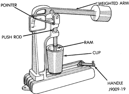
CYLINDER BLOCK
CLEANING
Thoroughly clean the oil pan and engine block gasket surfaces.
Use compressed air to clean out: • The galley at the oil filter adaptor hole, the filter bypass hole.
• The front and rear oil galley holes. • The feed holes for the crankshaft main bearings. Once the block has been completely cleaned, apply Loctite PST pipe sealant with Teflon 592 to the threads of the front and rear oil galley plugs. Tighten the plugs to 41 N·m (30 ft. lbs.) torque.
INSPECTION—CYLINDER BORE
(1) It is mandatory to use a dial bore gauge to measure each cylinder bore diameter (Fig. 65). To correctly select the proper size piston, a cylinder bore gauge, capable of reading in 0.003 mm (.0001 in.) INCREMENTS is required. If a bore gauge is not available, do not use an inside micrometer.
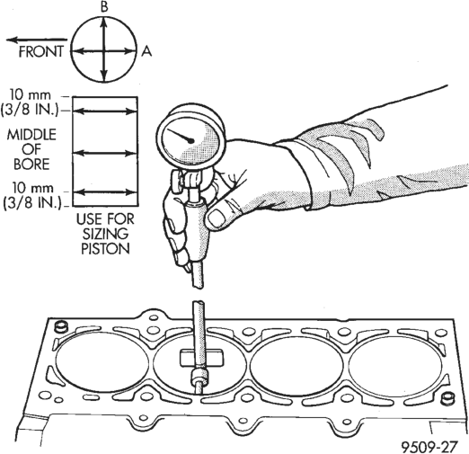
(2) Measure the inside diameter of the cylinder bore at three levels below top of bore. Start perpendicular (across or at 90 degrees) to the axis of the crankshaft and then take two additional reading.
(3) Measure the cylinder bore diameter crosswise to the cylinder block near the top of the bore. Repeat the measurement near the middle of the bore, then repeat the measurement near the bottom of the bore.
(4) Determine taper by subtracting the smaller diameter from the larger diameter.
(5) Rotate measuring device 90° and repeat steps above.
(6) Determine out-of-roundness by comparing the difference between each measurement.
(7) If cylinder bore taper does not exceed 0.025 mm (0.001 inch) and out-of-roundness does not exceed 0.025 mm (0.001 inch), the cylinder bore can be honed. If the cylinder bore taper or out- of-round condition exceeds these maximum limits, the cylinder must be bored and then honed to accept an oversize piston. A slight amount of taper always exists in the cylinder bore after the engine has been in use for a period of time.
HONING—CYLINDER BORE
The honing operation should be closely coordinated with the fitting of pistons and rings. This will ensure specified clearances are maintained.
Refer to Standard Service Procedures in the beginning of this Group for the proper honing of cylinder bores.
SPECIFICATIONS
4.0L ENGINE SPECIFICATIONS
Camshaft Hydraulic Tappet Clearance . . . . . . . . . . . .Zero Lash Bearing Clearance. . . . . . . . . . . . .0.025 to 0.076 mm
(0.001 to 0.003 in.) Bearing Journal Diameter No. 1 . . . . . . . .51.54 to 51.56 mm (2.029 to 2.030 in.) No. 2 . . . . . . . .51.28 to 51.31 mm (2.019 to 2.020 in.) No. 3 . . . . . . . .51.03 to 51.05 mm (2.009 to 2.010 in.) No. 4 . . . . . . . .50.78 to 50.80 mm (1.999 to 2.000 in.) Base Circle Runout . . . . . . . . . . . . . .0.03 mm - max.
(0.001 in. - max.) Valve Lift . . . . . . . . . . . . . . . . . .10.29 mm (0.405 in.) Intake Valve Timing Opens . . . . . . . . . . . . . . . . . . . . . . . . . . .12.4° BTDC Closes . . . . . . . . . . . . . . . . . . . . . . . . . . .60.9° ABDC Exhaust Valve Timing Opens . . . . . . . . . . . . . . . . . . . . . . . . . . . .49.8 BBDC Closes. . . . . . . . . . . . . . . . . . . . . . . . . . . .29.2° ATDC Valve Overlap. . . . . . . . . . . . . . . . . . . . . . . . . . .42.6° Intake Duration . . . . . . . . . . . . . . . . . . . . . . . .253.3° Exhaust Duration. . . . . . . . . . . . . . . . . . . . . . . .259.° Crankshaft End Play . . . . . . . . . . . . . . . . . . . .0.038 to 0.165 mm
(0.0015 to 0.0065 in.) Main Bearing Journal Diameter
No. 1-6 . . . . . . . . . . . . . . . . . .63.489 to 63.502 mm
(2.4996 to 2.5001 in.) Main Bearing Journal Diameter
No. 7 . . . . . . . . . . . . . . . . . . .63.449 to 63.487 mm
(2.4980 to 2.4995 in.) Main Bearing Journal
Width No. 1 . . . . . . . . . . . . . . . .27.58 to 27.89 mm
(1.086 to 1.098 in.) Main Bearing Journal
Width No. 3 . . . . . . . . . . . . . . . .32.28 to 32.33 mm
(1.271 to 1.273 in.) Main Bearing Journal
Width No. 2-4-5-6-7 . . . . . . . . . .30.02 to 30.18 mm
(1.182 to 1.188 in.) Main Bearing Clearance . . . . . . . . . .0.03 to 0.06 mm
(0.001 to 0.0025 in.) Main Bearing Clearance (Preferred) . . . . . .0.051 mm
(0.002 in.)
Connecting Rod Journal
Diameter . . . . . . . . . . . . . . . . .53.17 to 53.23 mm (
2.0934 to 2.0955 in.) Connecting Rod Journal Width . . .27.18 to 27.33 mm
(1.070 to 1.076 in.) Out-of-Round (Max. All Journals) . . . . . . . .0.013 mm
(0.0005 in.) Taper (Max. – All Journals) . . .0.013 mm (0.0005 in.) Cylinder Block Deck Height. . . . . . . . . . . . . . . .240.03 to 240.18 mm
(9.450 to 9.456 in.) Deck Clearance (Below Block) . . . . . . . . . .0.546 mm
(0.0215 in.) Cylinder Bore Diameter—
Standard . . . . . . . . . . . . . . . . . .98.45 to 98.48 mm
(3.8759 to 3.8775 in.) Cylinder Bore Diameter—
Taper (Max.) . . . . . . . . . . . . . .0.025 mm (0.001 in.) Cylinder Bore Diameter—
Out-of-Round . . . . . . . . . . . . .0.025 mm (0.001 in.) Tappet Bore Diameter . . . . . . . .23.000 to 23.025 mm
(0.9055 to 0.9065 in.) Flatness . . . . . . . . . . . . . . . . . . .0.03 mm per 25 mm
(0.001 in. per 1 in.) Flatness . . . . . . . . . . . . . . . . . .0.05 mm per 152 mm
(0.002 in. per 6 in.) Flatness Max. . . . . . . .0.20 mm max. for total length
(0.008 in. max. for total length) Main Bearing Bore
Diameter . . . . . . . . . . . . . .68.3514 to 68.3768 mm
(2.691 to 2.692 in.) Connecting Rods Total Weight (Less Bearing) . . . . . .657 to 665 grams
(23.17 to 23.45 oz.) Length (Center-to-Center) . . . . .155.52 to 155.62 mm
(6.123 to 6.127 in.) Piston Pin Bore Diameter . . . . . . .23.59 to 23.62 mm
(0.9288 to 0.9298 in.) Bore (Less Bearings) . . . . . . . . . . .56.08 to 56.09 mm
(2.2080 to 2.2085 in.) Bearing Clearance. . . . . . . . . . . . .0.025 to 0.076 mm
(0.001 to 0.003 in.) Bearing Clearance (Preferred). . . .0.044 to 0.050 mm (0.0015 to 0.0020 in.) Side Clearance . . . . . . . . . . . . . . . . .0.25 to 0.48 mm
(0.010 to 0.019 in.) Twist (Max.) . . . . . . . . . . . . . . . . .0.001 mm per mm
(0.001 in. per inch) Bend Max.) . . . . . . . . . . . . . . . . . .0.001 mm per mm
(0.001 in. per inch.) Cylinder Compression Pressure Ratio. . . . . . . . . . . . . . . . . . . . . . . . . . . . . . . . . .8.7:1 Pressure Range. . . .827 to 1,034 kPa (120 to 150 psi) Max. Variation Between Cylinders . .206 kPa (30 psi)
Cylinder Head Combustion Chamber. . . . . . . . . . . .52.22 to 58.22 cc
(3.37 to 3.55 cu. in.) Valve Guide I.D. (Integral). . . . . . .7.9 mm (0.312 in.) Valve Stem-to-Guide Clearance . . .0.025 to 0.076 mm (0.001 to 0.003 in.) Intake Valve Seat Angle . . . . . . . . . . . . . . . . . . .44.5° Exhaust Valve Seat Angle . . . . . . . . . . . . . . . . .44.5° Valve Seat Width . . . . . . . . . . . . . . .1.02 to 1.52 mm
(0.040 to 0.060 in.) Valve Seat Runout . . . . . . . . . .0.064 mm (0.0025 in.) Flatness . . . . . . . . . . . . . . . . . . .0.03 mm per 25 mm
(0.001 in. per 1 in.) Flatness . . . . . . . . . . . . . . . . . .0.05 mm per 152 mm
(0.002 in. per 6 in.) Flatness Max. . . . . . .0.20 mm - max. for total length
(0.008 in. max. for total length) Rocker Arms, Push Rods & Tappets Rocker Arm Ratio . . . . . . . . . . . . . . . . . . . . . . . .1.6:1 Push Rod Length . . . . . . . . . .244.856 to 245.364 mm
(9.640 to 9.660 in.) Push Rod Diameter. . . . . . . . . . . . . .7.92 to 8.00 mm
(0.312 to 0.315 in.) Hydraulic Tappet Diameter . . . .22.962 to 22.974 mm
(0.904 to 0.9045 in.) Tappet-to-Bore Clearance . . . . . . .0.025 to 0.063 mm
(0.001 to 0.0025 in.) Valves Length (Tip-to-Gauge Dimension Line)
Intake. . . . . . . . . . . . . . . . .122.479 to 122.860 mm
(4.822 to 4.837 in.) Length (Tip-to-Gauge Dimension Line)
Exhaust . . . . . . . . . . . . . . .122.860 to 123.241 mm
(4.837 to 4.852 in.) Valve Stem Diameter . . . . . . . . . .7.899 to 7.925 mm
(0.311 to 0.312 in.) Stem-to-Guide Clearance. . . . . . . .0.025 to 0.076 mm
(0.001 to 0.003 in.) Valve Head Diameter—
Intake . . . . . . . . . . . . . . . . . .48.387 to 48.641 mm
(1.905 to 1.915 in.) Valve Head Diameter—
Exhaust . . . . . . . . . . . . . . . . .37.973 to 38.227 mm
(1.495 to 1.505 in.) Valve Face Angle—Intake . . . . . . . . . . . . . . . . . . .45° Valve Face Angle—Exhaust. . . . . . . . . . . . . . . . . .45° Tip Refinishing (Max. Allowable) . . . . . . . . .0.25 mm
(0.010 in.) Valve Springs Free Length (Approx.) . . . . . . . .47.65 mm (1.876 in.) Spring Tension—Valve
Closed. . . . . . . . . . . . . .271 to 307 N @ 41.656 mm
(61 to 69 lbf. @ 1.64 in.)
Spring Tension—Valve
Open . . . . . . . . . . . . .818.5 to 871.9 N @ 30.89 mm
(184 to 196 lbf @ 1.216 in.) Inside Diameter . . . . . . . . . . . .21.0 mm to 21.51 mm
(0.827 to 0.847 in.) Pistons Weight (Less Pin) . . . . . . . . . . . . . .563 to 567 grams
(19.86 to 20.00 oz.) Piston Pin Bore (Centerline to
Piston Top). . . . . . . . . . . . . . . . .40.61 to 40.72 mm
(1.599 to 1.603 in.) Piston-to-Bore Clearance. . . . . . . .0.033 to 0.053 mm
(0.0013 to 0.0021 in.) Piston-to-Bore Clearance
(Preferred) . . . . . . . . . . . . . . . . .0.033 to 0.038 mm
(0.0013 to 0.0015 in.) Ring Gap Clearance—
Top Compression Ring. . . . . . . . .0.229 to 0.610mm
(0.0090 to 0.0240 in.) Ring Gap Clearance—
2nd Compression Ring . . . . . . . .0.483 to 0.965 mm (0.0190 to 0.0380 in.) Ring Gap Clearance—
Oil Control Steel Rails . . . . . . . .0.254 to 1.500 mm
(0.010 to 0.060 in.) Ring Side Clearance—
Compression Rings . . . . . . . . . .0.042 to 0.084 mm
(0.0017 to 0.0033 in.) Ring Side Clearance—
Oil Control Rings. . . . . . . . . . . . . .0.06 to 0.21 mm
(0.0024 to 0.0083 in.) Piston Ring Groove Height—
Compression Rings . . . . . . . . . .1.530 to 1.555 mm
(0.0602 to 0.0612 in.) Piston Ring Groove Height—
Oil Control Ring. . . . . . . . . . . . .4.035 to 4.060 mm
(0.1589 to 0.1598 in.) Piston Ring Groove Diameter—
Compression Rings . . . . . . . . . . .88.3 to 88.55 mm
(3.476 to 3.486 in.) Piston Ring Groove Diameter—
Oil Control Ring. . . . . . . . . . . . .90.35 to 90.60 mm
(3.557 to 3.566 in.) Piston Pin Bore Diameter . . . . .23.647 to 23.655 mm
(0.9310 to 0.9313 in.) Piston Pin Diameter . . . . . . . . .23.637 to 23.640 mm
(0.9306 to 0.9307 in.) Piston-to-Pin Clearance . . . . .0.0076 to 0.0178 mm—
Loose (0.0003 to 0.0007 in. Loose) Piston-to-Pin Clearance
(Preferred) . . . . . . . . . . . . . .0.013 mm (0.0005 in.) Piston-to-Pin Connecting Rod
(Press Fit) . . . . . . . . . . . . . . . . . .8.9 kN (2000 lbf.) Oil Pump Gear-to-Body Clearance (Radial) . .0.051 to 0.102 mm
(0.002 to 0.004 in.)
Gear-to-Body Clearance (Radial)
(Preferred) . . . . . . . . . . . . . . .0.051 mm (0.002 in.) Gear End Clearance—
Plastigage . . . . . . . . . . . . . . . . .0.051 to 0.152 mm
(0.002 to 0.006 in.) Gear End Clearance—Plastigage
(Preferred) . . . . . . . . . . . . . . .0.051 mm (0.002 in.) Gear End Clearance—
Feeler Gauge . . . . . . . . . . . . .0.1016 to 0.2032 mm
(0.004 to 0.008 in.) Gear End Clearance—Feeler Gauge
(Preferred) . . . . . . . . . . . . . .0.1778 mm (0.007 in.) Oil Pressure At Idle Speed (600 rpm). . . . . . . . . .89.6 kPa (13 psi) At 1600 rpm & Higher . . . . . . . . . . . .255 to 517 kPa
(37 to 75 psi) Oil Pressure Relief . . . . . . . . . . . . . .517 kPa (75 psi)
TORQUE SPECIFICATIONS
DESCRIPTION TORQUE A/C Compressor Bracket-to-Engine Bolts . . . . . . . . . . . . . . . . . . . . . . .34 N·m (25 ft. lbs.) A/C Compressor Mounting Bolts . . . . . . . . . . . . . . .27 N·m (20 ft. lbs.) A/C Low Pressure Service Valve Nut . . . . . . . . . . . . . . . . . . . . . . . .38 N·m (28 ft. lbs.) Block Heater Nut . . . . . . . . . . . . . . . . . . . . . . .1.8 N·m (16 in. lbs.) Camshaft Sprocket Bolt. . . . . . . . . . . . . . . . . . . . . . .108 N·m (80 ft. lbs.) Connecting Rod Nuts . . . . . . . . . . . . . . . . . . . . . . .45 N·m (33 ft. lbs.) Cylinder Block Drain Plugs . . . . . . . . . . . . . . . . .41 N·m (30 ft. lbs.) Cylinder Head Bolts #1–10 & #12–14 . . . . . . . .149 N·m (110 ft. lbs.) Bolt #11. . . . . . . . . . . . . . . . . . .135 N·m (100 ft. lbs.) Cylinder Head Cover Bolts. . . . . . . . . . . . . . . . . . . . . .13 N·m (115 in. lbs.) Engine Mounts—Front Support Bracket Bolts . . . . . . . . .61 N·m (45 ft. lbs.) Support Cushion Bolts/Nuts . . . . .41 N·m (30 ft. lbs.) Support Cushion Bracket Bolts. . .54 N·m (40 ft. lbs.) Support Cushion Bracket
Stud Nuts . . . . . . . . . . . . . . . . .41 N·m (30 ft. lbs.) Support Cushion Thru-Bolt . . . . .65 N·m (48 ft. lbs.) Engine Mounts—Rear Crossmember-to-Sill Bolts
(Automatic) . . . . . . . . . . . . . . . .41 N·m (30 ft. lbs.) Insulator Stud Assembly Nut . . . .41 N·m (30 ft. lbs.) Support Cushion/Crossmember
Nuts . . . . . . . . . . . . . . . . . . . .22 N·m (192 in. lbs.) Support Cushion/Bracket Nuts
(Manual) . . . . . . . . . . . . . . . . . .75 N·m (55 ft. lbs.)
DESCRIPTION TORQUE Transmission Support Bracket Bolt
(Manual) . . . . . . . . . . . . . . . . . .46 N·m (34 ft. lbs.) Transmission Support Bracket/
Cushion Bolt (4WD Auto) . . . . . .75N·m (55 ft. lbs.) Transmission Support Adaptor
Bracket Bolts (2WD Auto) . . . . .75N·m (55 ft. lbs.) Exhaust Manifold/Pipe Nuts . . . . . . . . . . . . . . . . . . . . . . .27 N·m (20 ft. lbs.) Flywheel/Converter Housing Bolts . . . . . . . . . . . . . . . . . . . . . . .38 N·m (28 ft. lbs.) Flywheel/Crankshaft Bolts . . . . . . . . . . . . . . . . . . . . .143 N·m (105 ft. lbs.) Front Cover-to-Block Bolts 1/4–20 . . . . . . . . . . . . . . . . . .7N·m (60 in. lbs.) Bolts 5/16–18. . . . . . . . . . . . . . . .22N·m (192 in. lbs.) Fuel Pump Bolts . . . . . . . . . . . . . . . . . . . . . . .22 N·m (16 ft. lbs.) Generator Adjusting Bolt. . . . . . . . . . . . . . . .24 N·m (18 ft. lbs.) Pivot Bolt/Nut. . . . . . . . . . . . . . . .38 N·m (28 ft. lbs.) Main Bearing Bolts . . . . . . . . . . . . . . . . . . . . . .108 N·m (80 ft. lbs.) Oil Filter Filter . . . . . . . . . . . . . . . . . . . . . .18 N·m (13 ft. lbs.) Oil Filter Adaptor Bolts . . . . . . . . . . . . . . .102 N·m (75 ft. lbs.) Oil Galley Plug . . . . . . . . . . . . . . . . . . . . . . .41 N·m (30 ft. lbs.) Oil Pan 1/4–20 Bolts . . . . . . . . . . . . . . . .14 N·m (129 in. lbs.) 5/16–18 Bolts . . . . . . . . . . . . . . .18 N·m (156 in. lbs.) Drain Plug . . . . . . . . . . . . . . . . . .34 N·m (25 ft. lbs.) Oil Pump Short Attaching Bolts . . . . . . . . . .14 N·m (10 ft. lbs.) Long Attaching Bolts . . . . . . . . . .23 N·m (17 ft. lbs.) Cover Bolts . . . . . . . . . . . . . . . . . .8 N·m (70 in. lbs.) Power Steering Pump Pressure Hose Nut . . . . . . . . . . . . . . . . . . . . . . . .52 N·m (38 ft. lbs.) Rocker Arm Assembly-to-Cylinder Head Capscrews . . . . . . . . . . . . . . . . . . .28 N·m (21ft. lbs.) Spark Plugs Plugs. . . . . . . . . . . . . . . . . . . . . . .37 N·m (27 ft. lbs.) Starting Motor Mounting Bolts . . . . . . . . . . . . . . .45 N·m (33 ft. lbs.) Thermostat Housing Bolts . . . . . . . . . . . . . . . . . . . . . . .18 N·m (13 ft. lbs.) Vibration Damper Bolts . . . . . . . . . . . . . . . . . . . . . .108 N·m (80 ft. lbs.) Water Pump/Block Bolts. . . . . . . . . . . . . . . . . . . . . .31 N·m (270 in. lbs.)
SPECIAL TOOLS
4.0L ENGINE
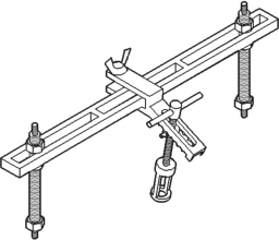
Valve Spring Compressor Tool MD-998772A
Timing Case Cover Alignment and Seal installation
Tool 6139
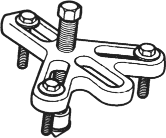
Vibration Damper Removal Tool 7697
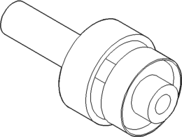
Rear Main Seal Installer Tool 6271A
5.2L ENGINE
INDEX
GENERAL INFORMATION
OIL PUMP PRESSURE . . . . . . . . . . . . . . . . . . . . 53 PISTON AND CONNECTING ROD ASSEMBLY . . 53 VALVES AND VALVE SPRINGS . . . . . . . . . . . . . 53 DESCRIPTION AND OPERATION
ENGINE COMPONENTS . . . . . . . . . . . . . . . . . . 56 ENGINE DESCRIPTION . . . . . . . . . . . . . . . . . . . 53 LUBRICATION SYSTEM . . . . . . . . . . . . . . . . . . . 54 SERVICE PROCEDURES
CRANKSHAFT MAIN BEARINGS . . . . . . . . . . . . 58 CRANKSHAFT . . . . . . . . . . . . . . . . . . . . . . . . . . 59 FITTING CONNECTING ROD BEARINGS . . . . . . 57 FITTING PISTON RINGS . . . . . . . . . . . . . . . . . . 57 FITTING PISTONS . . . . . . . . . . . . . . . . . . . . . . . 57 MEASURING TIMING CHAIN STRETCH . . . . . . . 56 VALVE TIMING . . . . . . . . . . . . . . . . . . . . . . . . . . 56 REMOVAL AND INSTALLATION
CAMSHAFT BEARINGS . . . . . . . . . . . . . . . . . . . 67 CAMSHAFT . . . . . . . . . . . . . . . . . . . . . . . . . . . . 66 CRANKSHAFT MAIN BEARINGS . . . . . . . . . . . . 68 CRANKSHAFT REAR OIL SEALS . . . . . . . . . . . . 72 CRANKSHAFT . . . . . . . . . . . . . . . . . . . . . . . . . . 70 CYLINDER HEAD COVER . . . . . . . . . . . . . . . . . 61 CYLINDER HEAD . . . . . . . . . . . . . . . . . . . . . . . . 62 DISTRIBUTOR DRIVE SHAFT BUSHING . . . . . . 68 ENGINE ASSEMBLY . . . . . . . . . . . . . . . . . . . . . . 60 ENGINE CORE OIL AND CAMSHAFT PLUGS . . 74 ENGINE MOUNTS—FRONT . . . . . . . . . . . . . . . . 59 ENGINE MOUNTS—REAR . . . . . . . . . . . . . . . . . 60
GENERAL INFORMATION
VALVES AND VALVE SPRINGS
The valves are arranged in-line and inclined 18°. The rocker pivot support and the valve guides are cast integral with the heads.
OIL PUMP PRESSURE
The MINIMUM oil pump pressure is 41.4 kPa (6 psi) at curb idle. The MAXIMUM oil pump pressure is 207-552 kPa (30-80 psi) at 3,000 RPM or more.
CAUTION: If oil pressure is ZERO at curb idle, DO NOT run engine at 3,000 RPM.
PISTON AND CONNECTING ROD ASSEMBLY
The pistons are elliptically turned so that the diameter at the pin boss is less than its diameter page page
FRONT CRANKSHAFT OIL SEAL . . . . . . . . . . . . 71 HYDRAULIC TAPPETS . . . . . . . . . . . . . . . . . . . . 63 OIL PAN . . . . . . . . . . . . . . . . . . . . . . . . . . . . . . . 69 OIL PUMP . . . . . . . . . . . . . . . . . . . . . . . . . . . . . 71 PISTON AND CONNECTING ROD ASSEMBLY . . 70 ROCKER ARMS AND PUSH RODS . . . . . . . . . . 61 TIMING CHAIN COVER . . . . . . . . . . . . . . . . . . . 64 TIMING CHAIN . . . . . . . . . . . . . . . . . . . . . . . . . . 66 VALVE SPRING AND STEM SEAL
REPLACEMENT-IN VEHICLE . . . . . . . . . . . . . 62 VALVES AND VALVE SPRINGS . . . . . . . . . . . . . 63 VIBRATION DAMPER . . . . . . . . . . . . . . . . . . . . . 64 DISASSEMBLY AND ASSEMBLY
CYLINDER BLOCK . . . . . . . . . . . . . . . . . . . . . . . 77 HYDRAULIC TAPPETS . . . . . . . . . . . . . . . . . . . . 75 OIL PUMP . . . . . . . . . . . . . . . . . . . . . . . . . . . . . 77 VALVE SERVICE . . . . . . . . . . . . . . . . . . . . . . . . 75 CLEANING AND INSPECTION
CRANKSHAFT INSPECTION OF JOURNALS . . . 78 CYLINDER BLOCK . . . . . . . . . . . . . . . . . . . . . . . 80 CYLINDER HEADS . . . . . . . . . . . . . . . . . . . . . . . 77 OIL PAN . . . . . . . . . . . . . . . . . . . . . . . . . . . . . . . 78 OIL PUMP . . . . . . . . . . . . . . . . . . . . . . . . . . . . . 78 PISTON AND CONNECTING ROD ASSEMBLY . . 78 SPECIFICATIONS
5.2L ENGINE . . . . . . . . . . . . . . . . . . . . . . . . . . . 81 SPECIAL TOOLS
5.2L ENGINE . . . . . . . . . . . . . . . . . . . . . . . . . . . 85 across the thrust face. This allows for expansion under normal operating conditions. Under operating temperatures, expansion forces the pin bosses away from each other, causing the piston to assume a more nearly round shape.
All pistons are machined to the same weight, regardless of size, to maintain piston balance.
The piston pin rotates in the piston only and is retained by the press interference fit of the piston pin in the connecting rod.
DESCRIPTION AND OPERATION
ENGINE DESCRIPTION
The 5.2 Liter (318 CID) eight-cylinder engine is a V-Type lightweight, single cam, overhead valve engine with hydraulic roller tappets (Fig. 1).
This engine is designed for unleaded fuel.
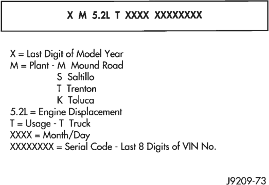
Engine lubrication system consists of a rotor type oil pump and a full flow oil filter.
The cylinders are numbered from front to rear; 1, 3, 5, 7 on the left bank and 2, 4, 6, 8 on the right bank. The firing order is 1-8-4-3-6-5-7- 2 (Fig. 2).
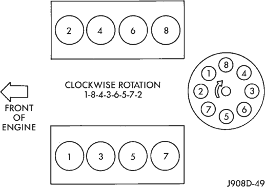
The engine serial number is stamped into a machined pad located on the left, front corner of the cylinder block. When component part replacement is necessary, use the engine type and serial number for reference (Fig. 3).
LUBRICATION SYSTEM
A gear—type positive displacement pump is mounted at the underside of the rear main bearing
cap. The pump draws oil through the screen and inlet tube from the sump at the rear of the oil pan. The oil is driven between the drive and idler gears and pump body, then forced through the outlet to the block. An oil gallery in the block channels the oil to the inlet side of the full flow oil filter. After passing through the filter element, the oil passes from the center outlet of the filter through an oil gallery that channels the oil up to the main gallery which extends the entire length on the right side of the block. The oil then goes down to the No. 1 main bearing, back up to the left side of the block and into the oil gallery on the left side of the engine.
Galleries extend downward from the main oil gallery to the upper shell of each main bearing. The crankshaft is drilled internally to pass oil from the main bearing journals to the connecting rod journals. Each connecting rod bearing has half a hole in it, oil passes through the hole when the rods rotate and the hole lines up, oil is then thrown off as the rod rotates. This oil throw off lubricates the camshaft lobes, distributor drive gear, cylinder walls, and piston pins.
The hydraulic valve tappets receive oil directly from the main oil gallery. The camshaft bearings receive oil from the main bearing galleries. The front camshaft bearing journal passes oil through the camshaft sprocket to the timing chain. Oil drains back to the oil pan under the number one main bearing cap.
The oil supply for the rocker arms and bridged pivot assemblies is provided by the hydraulic valve tappets which pass oil through hollow push rods to a hole in the corresponding rocker arm. Oil from the rocker arm lubricates the valve train components. The oil then passes down through the push rod guide holes, and the oil drain back passages in the cylinder head past the valve tappet area, and returns to the oil pan.
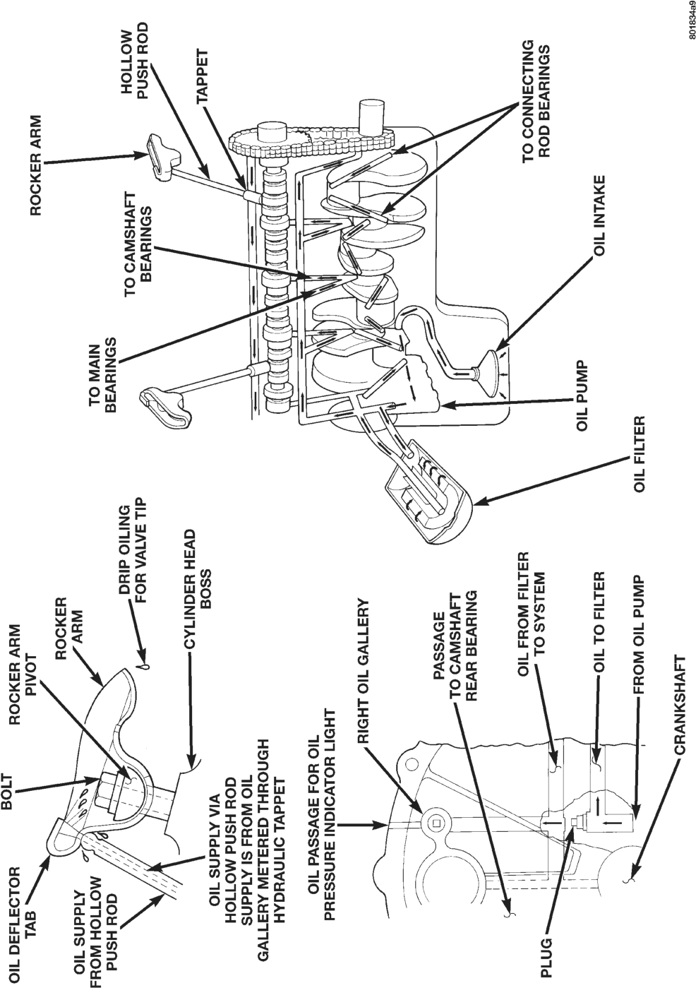
ENGINE COMPONENTS
CYLINDER HEAD
The alloy cast iron cylinder heads (Fig. 5) are held in place by 10 bolts. The spark plugs are located in the peak of the wedge between the valves.
The 5.2L cylinder head is identified by the foundry mark NH.
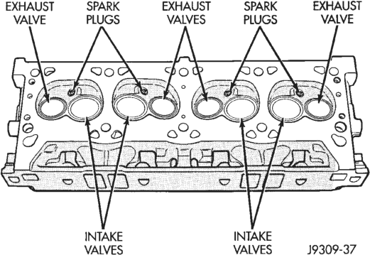
PISTONS
All pistons are machined to the same weight, regardless of size, to maintain piston balance.
The pistons are elliptically turned so that the diameter at the pin boss is less than its diameter across the thrust face. This allows for expansion under normal operating conditions. Under operating temperatures, expansion forces the pin bosses away from each other, causing the piston to assume a more nearly round shape.
The piston pin rotates in the piston only and is retained by the press interference fit of the piston pin in the connecting rod.
SERVICE PROCEDURES
VALVE TIMING
(1) Turn crankshaft until the No.6 exhaust valve is closing and No.6 intake valve is opening.
(2) Insert a 6.350 mm (1/4 inch) spacer between rocker arm pad and stem tip of No.1 intake valve. Allow spring load to bleed tappet down giving in effect a solid tappet.
(3) Install a dial indicator so plunger contacts valve spring retainer as nearly perpendicular as possible. Zero the indicator.
(4) Rotate the crankshaft clockwise (normal running direction) until the valve has lifted 0.863 mm (0.034 inch). The timing of the crankshaft should now read from 10° before top dead center to 2° after top dead center. Remove spacer.
CAUTION: DO NOT turn crankshaft any further clockwise as valve spring might bottom and result in serious damage.
If reading is not within specified limits: • Check sprocket index marks. • Inspect timing chain for wear. • Check accuracy of DC mark on timing indicator.
MEASURING TIMING CHAIN STRETCH
NOTE: To access timing chain Refer to Timing Chain Cover in Removal and Installation Section.
(1) Place a scale next to the timing chain so that any movement of the chain may be measured.
(2) Place a torque wrench and socket over camshaft sprocket attaching bolt. Apply torque in the direction of crankshaft rotation to take up slack; 41 N·m (30 ft. lbs.) torque with cylinder head installed or 20 N·m (15 ft. lbs.) torque with cylinder head removed. With a torque applied to the camshaft sprocket bolt, crankshaft should not be permitted to move. It may be necessary to block the crankshaft to prevent rotation.
(3) Hold a scale with dimensional reading even with the edge of a chain link. With cylinder heads installed, apply 14 N·m (30 ft. lbs.) torque in the reverse direction. With the cylinder heads removed, apply 20 N·m (15 ft. lbs.) torque in the reverse direction. Note the amount of chain movement (Fig. 6).
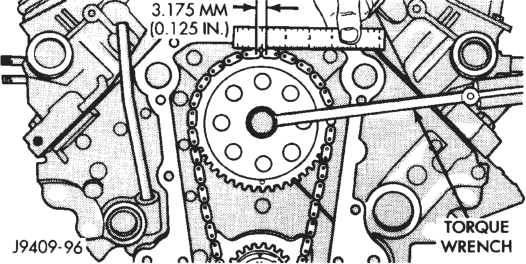
(4) Install a new timing chain, if its movement exceeds 3.175 mm (1/8 inch).
(5) If chain is not satisfactory, remove camshaft sprocket attaching bolt and remove timing chain with crankshaft and camshaft sprockets.
(6) Place both camshaft sprocket and crankshaft sprocket on the bench with timing marks on exact imaginary center line through both camshaft and crankshaft bores.
(7) Place timing chain around both sprockets. (8) Turn crankshaft and camshaft to line up with keyway location in crankshaft sprocket and in camshaft sprocket.
(9) Lift sprockets and chain (keep sprockets tight against the chain in position as described).
(10) Slide both sprockets evenly over their respective shafts and use a straightedge to check alignment of timing marks (Fig. 7).
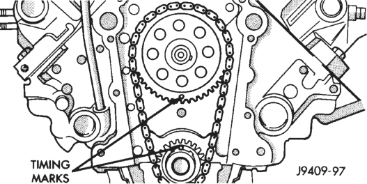
(11) Install the camshaft bolt. Tighten the bolt to 47 N·m (35 ft. lbs.) torque. (12) Check camshaft end play. The end play should be 0.051-0.152 mm (0.002-0.006 inch) with a new thrust plate and up to 0.254 mm (0.010 inch) with a used thrust plate. If not within these limits install a new thrust plate.
FITTING PISTONS
Piston and cylinder wall must be clean and dry. Specified clearance between the piston and the cylinder wall is 0.013-0.038 mm (0.0005-0.0015 inch) at 21°C (70°F). Piston diameter should be measured at the top of skirt, 90° to piston pin axis location A in (Fig. 8). Cylinder bores should be measured halfway down the cylinder bore and transverse to the engine crankshaft center line.
Pistons and cylinder bores should be measured at normal room temperature, 21°C (70°F).
FITTING PISTON RINGS
(1) Measurement of end gaps:
(a) Measure piston ring gap 2 inches from bottom of cylinder bore. An inverted piston can be used to push the rings down to ensure positioning rings squarely in the cylinder bore before measuring.
(b) Insert feeler gauge in the gap. The top compression ring gap should be between 0.254-0.508 mm (0.010-0.020 inch). The second compression ring gap should be between 0.508-0.762 mm (0.020- 0.030 inch). The oil ring gap should be 0.254-1.270 mm (0.010-0.050 inch).
(c) Rings with insufficient end gap may be properly filed to the correct dimension. Rings with excess gaps should not be used. (2) Install rings and confirm ring side clearance:
(a) Install oil rings being careful not to nick or scratch the piston. Install the oil control rings accord-
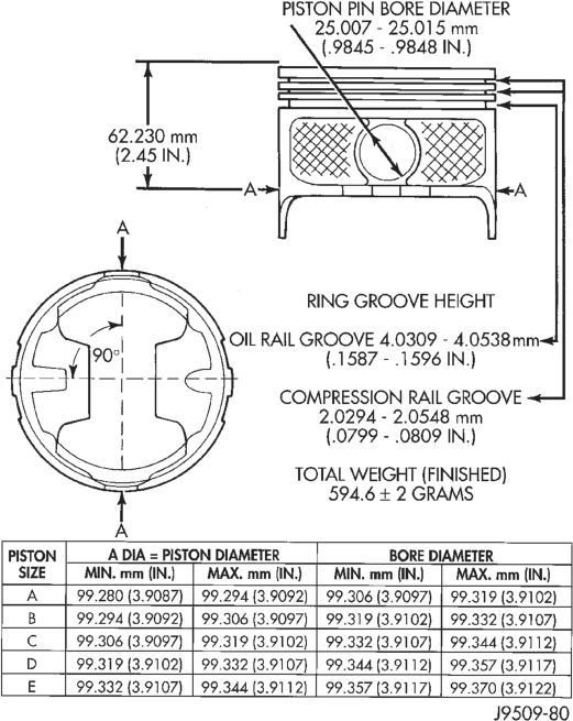
ing to instructions in the package. It is not necessary to use a tool to install the upper and lower rails. Insert oil rail spacer first, then side rails.
(b) Install the second compression rings using Installation Tool C-4184. The compression rings must be installed with the identification mark face up (toward top of piston) and chamfer facing down. An identification mark on the ring is a drill point, a stamped letter “O”, an oval depression or the word TOP (Fig. 9) (Fig. 11).
(c) Using a ring installer, install the top compression ring with the chamfer facing up (Fig. 10) (Fig. 11). An identification mark on the ring is a drill point, a stamped letter “O”, an oval depression or the word TOP facing up.
(d) Measure side clearance between piston ring and ring land. Clearance should be 0.074-0.097 mm (0.0029-0.0038 inch) for the compression rings. The steel rail oil ring should be free in groove, but should not exceed 0.246 mm (0.0097 inch) side clearance.
(e) Pistons with insufficient or excessive side clearance should be replaced.
FITTING CONNECTING ROD BEARINGS
Fit all rods on a bank until completed. DO NOT alternate from one bank to another, because connect-
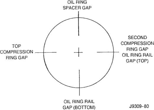
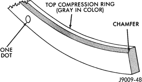
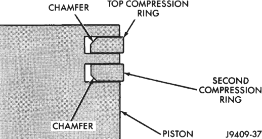
ing rods and pistons are not interchangeable from one bank to another.
The bearing caps are not interchangeable and should be marked at removal to ensure correct assembly.
Each bearing cap has a small V-groove across the parting face. When installing the lower bearing shell, make certain that the V-groove in the shell is in line with the V-groove in the cap. This provides lubrication of the cylinder wall in the opposite bank.
The bearing shells must be installed so that the tangs are in the machined grooves in the rods and caps.
Limits of taper or out-of-round on any crankshaft journals should be held to 0.025 mm (0.001 inch).
Bearings are available in 0.025 mm (0.001 inch), 0.051 mm (0.002 inch), 0.076 mm (0.003 inch), 0.254 mm (0.010 inch) and 0.305 mm (0.012 inch) undersize. Install the bearings in pairs. DO NOT use a new bearing half with an old bearing half. DO NOT file the rods or bearing caps.
CRANKSHAFT MAIN BEARINGS
Bearing caps are not interchangeable and should be marked at removal to ensure correct assembly. Upper and lower bearing halves are NOT interchangeable. Lower main bearing halves of No.2 and 4 are interchangeable.
Upper and lower No.3 bearing halves are flanged to carry the crankshaft thrust loads. They are NOT interchangeable with any other bearing halves in the engine (Fig. 13). Bearing shells are available in standard and the following undersizes: 0.25 mm (0.001 inch), 0.051 mm (0.002 inch), 0.076 mm (0.003 inch), 0.254 mm (0.010 inch) and 0.305 mm (0.012 inch). Never install an undersize bearing that will reduce clearance below specifications.
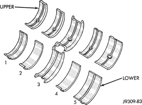
CRANKSHAFT
A crankshaft which has undersize journals will be stamped with 1/4 inch letters on the milled flat on the No.8 crankshaft counterweight (Fig. 14).
FOR EXAMPLE: R2 stamped on the No.8 crankshaft counterweight indicates that the No.2 rod journal is 0.025 mm (0.001 in) undersize. M4 indicates that the No.4 main journal is 0.025 mm (0.001 in) undersize. R3 M2 indicates that the No.3 rod journal and the No.2 main journal are 0.025 mm (0.001 in) undersize.
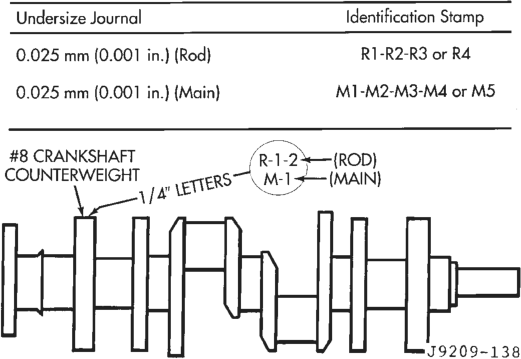
When a crankshaft is replaced, all main and connecting rod bearings should be replaced with new bearings. Therefore, selective fitting of the bearings is not required when a crankshaft and bearings are replaced.
REMOVAL AND INSTALLATION
ENGINE MOUNTS—FRONT
REMOVAL
(1) Disconnect the negative cable from the battery. (2) Position fan to assure clearance for radiator top tank and hose.
CAUTION: DO NOT lift the engine by the intake manifold.
(3) Install engine lifting fixture. (4) Raise vehicle on hoist. (5) Remove the engine support insulator thru-bolts and nuts (Fig. 15) (Fig. 16).
(6) Raise engine SLIGHTLY. Remove the engine support insulator bolts. Remove the engine support insulator assembly.
(7) If required, remove the sill bracket assembly.
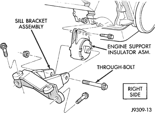
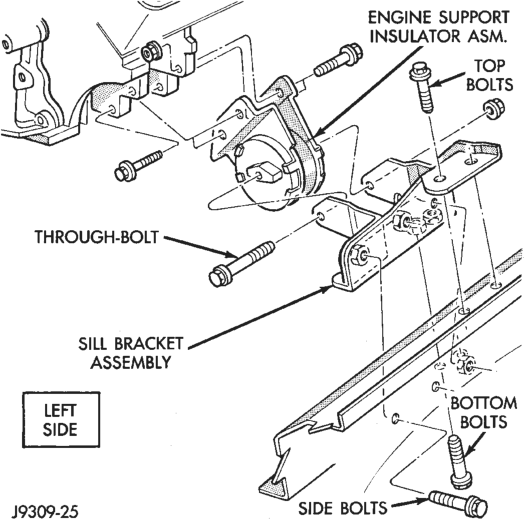
INSTALLATION
(1) If the sill bracket assembly was removed, install the bracket to the sill assembly.
(a) RIGHT SIDE—Install the sill bracket assembly onto the sill assembly (Fig. 15). Install and tighten the bolts to 65 N·m (48 ft. lbs.) torque.
(b) LEFT SIDE—Install the sill bracket assembly onto the sill assembly (Fig. 16). Install and tighten the 2 top bolts to 65 N·m (48 ft. lbs.) torque. Install and tighten the 2 side bolts to 95 N·m (70 ft. lbs.) torque. Install and tighten the 2 bottom bolts to 121 N·m (89 ft. lbs.) torque. (2) With the engine raised SLIGHTLY, position engine support insulator assembly onto the engine block (Fig. 15) (Fig. 16). Install bolts and tighten to 88 N·m (65 ft. lbs.) torque.
(3) Lower engine with lifting fixture while aligning engine support insulator assembly into sill bracket assembly.
(4) Install the thru-bolt and nut. Tighten the RIGHT SIDE nut to 81 N·m (60 ft. lbs.) torque. Tighten the LEFT SIDE nut to 81 N·m (60 ft. lbs.) torque.
(5) Lower the vehicle. (6) Remove lifting fixture. (7) Connect the negative cable to the battery.
ENGINE MOUNTS—REAR
REMOVAL
(1) Disconnect the negative cable from the battery. (2) Raise the vehicle on a hoist. (3) Support the transmission with a jack. (4) Remove engine mount bracket thru-bolt (Fig. 17). (5) Raise the transmission and engine SLIGHTLY. (6) Remove stud nuts attaching engine mount clevis bracket to crossmember (Fig. 17). Remove bracket.
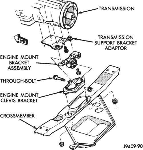
(7) Remove the engine mount bracket assembly from the adaptor (Fig. 17).
(8) If required, remove the transmission support bracket adaptor.
INSTALLATION
(1) If the transmission support bracket adaptor was removed, position the adaptor to the transmission (Fig. 17). Tighten the bolts to 60 N·m (44 ft. lbs.) torque.
(2) Install the engine mount clevis bracket onto crossmember. Tighten the stud nuts to 41 N·m (30 ft. lbs) torque.
(3) Install the engine mount bracket assembly to the adaptor. Install the bolts and tighten to 75 N·m (55 ft. lbs.) torque.
(4) Lower the transmission and engine while aligning the engine mount bracket assembly to the engine mount clevis bracket.
(5) Install thru-bolt and tighten the nut to 65 N·m (48 ft. lbs.) torque.
(6) Remove transmission jack. (7) Lower the vehicle. (8) Connect the negative cable to the battery.
ENGINE ASSEMBLY
REMOVAL
(1) Scribe hood hinge outlines on hood and remove the hood.
(2) Remove the battery. (3) Drain cooling system. (4) Remove the air cleaner and tube. (5) Set fan shroud aside. (6) Remove radiator and heater hoses. Remove the radiator (refer to Group 7, Cooling System).
(7) Remove the vacuum lines. (8) Remove the distributor cap and wiring. (9) Disconnect the accelerator linkage. (10) Perform the Fuel System Pressure Release procedure (refer to Group 14, Fuel System).
(11) Remove throttle body. (12) Remove the starter wires. (13) Remove the oil pressure wire. (14) Discharge the air conditioning system, if equipped (refer to Group 24, Heating and Air Conditioning for service procedures).
(15) Remove air conditioning hoses. (16) Disconnect the power steering hoses, if equipped.
(17) Remove starter motor (refer to Group 8B, Battery/Starter Service).
(18) Remove the generator (refer to Group 8C, Generator Service).
(19) Raise and support the vehicle on a hoist. (20) Disconnect exhaust pipe at manifold. (21) Support automatic transmission with a transmission stand. This will assure that the torque converter will remain in proper position in the transmission housing.
(22) Remove bell housing bolts and inspection plate. Attach C-clamp on front bottom of transmission torque converter housing to prevent torque converter from coming out.
(23) Remove torque converter drive plate bolts from torque converter drive plate. Mark converter and drive plate to aid in assembly.