Electrically Heated Systems — 1996 Jeep Grand Cherokee ZJ Service Manual
Pages 430–439 · 10 pages · 5 words repaired
The grid lines and bus bars are highly resistant to abrasion. However, it is possible for an open circuit to occur in an individual grid line, resulting in no current flow through the line. The grid lines can be damaged or scraped off with sharp instruments. Care should be taken when cleaning the glass or removing foreign materials, decals, or stickers from the glass. Normal glass cleaning solvents or hot water used with rags or toweling is recommended.
A repair kit is available to repair the grid lines and bus bars, or to reinstall the heated glass pigtail wires.
HEATED MIRRORS
The heated mirrors are controlled by the rear window defogger switch. The heater elements in the mirror are activated only when the rear window defogger switch is in the On position. The heater elements in the mirrors cannot be repaired and, if faulty, the entire mirror head must be replaced. Refer to Group 8T - Power Mirrors for the diagnosis and service of this component.
DEFOGGER SWITCH
The rear window defogger switch is mounted in the right instrument panel switch pod, right of the steering column. The momentary-type switch provides a hard-wired ground signal to the Body Control Module (BCM) each time it is depressed. The BCM responds by energizing or de-energizing the rear window defogger relay.
Energizing the rear window defogger relay provides current to the rear window defogger grid and the Light-Emitting Diode (LED) in the switch, which lights to indicate that the defogger system is turned on. The defogger switch and LED cannot be repaired. If faulty, the right switch pod unit must be replaced.
DEFOGGER RELAY
The rear window defogger relay is a International Standards Organization (ISO)-type relay. The defogger relay is a electro-mechanical device that switches fused battery current to the rear glass heating grid and the light-emitting diode of the defogger switch, when the body control module grounds the relay coil. See the Diagnosis and Testing section of this group for more information on the defogger relay’s operation.
The defogger relay is located in the junction block, on the right cowl side panel below the instrument panel in the passenger compartment. The defogger relay cannot be repaired and, if faulty, it must be replaced.
BODY CONTROL MODULE
A Body Control Module (BCM) is used on this model to control and integrate many of the vehicle’s electrical functions and features. The BCM contains a central processing unit and interfaces with other modules in the vehicle on the Chrysler Collision Detection (CCD) data bus network.
The CCD data bus network allows the sharing of sensor information. This helps to reduce wiring harness complexity, reduce internal controller hardware, and reduce component sensor current loads. At the same time, this system provides increased reliability, enhanced diagnostics, and allows the addition of many new feature capabilities.
One of the functions and features that the BCM supports and controls, is the Defogger System. The BCM receives hard-wired inputs from the defogger switch and the ignition switch. In its role as the defogger system timer and controller, the programming in the BCM allows it to process the information from these inputs and send a control output, which grounds the coil of the defogger relay. The BCM also sends a defogger switch status message to the Driver Door Module (DDM) and Passenger Door Module (PDM) on the CCD data bus. The DDM and PDM respond by controlling the current feeds to their respective outside rear view mirror heating elements.
The BCM is mounted under the left end of the instrument panel, behind the instrument panel support armature and below the left switch pod. Refer to Group 8E - Instrument Panel Systems for removal and installation procedures. For diagnosis of the BCM or the CCD data bus, refer to the proper Body Diagnostic Procedures Manual. The BCM can only be serviced by an authorized repair station. Refer to the Warranty Policies and Procedures Manual for a listing of authorized repair stations.
DIAGNOSIS AND TESTING
DEFOGGER SYSTEM
For circuit descriptions and diagrams, refer to 8W-48 - Rear Window Defogger in Group 8W - Wiring Diagrams. Electrically heated defogger operation can be confirmed in one of the following manners:
1. Turn the ignition switch to the On position. While monitoring the instrument panel voltmeter, set the defogger switch in the On position. When the defogger switch is turned On, a distinct voltmeter needle deflection should be noted.
2. Turn the ignition switch to the On position. Set the defogger switch in the On position. The defogger system operation can be checked by feeling the glass. A distinct difference in temperature between the grid lines and the adjacent clear glass or the mirror glass can be detected within three to four minutes of operation.
3. Using a 12-volt DC voltmeter, contact the rear glass heating grid terminal A (passenger’s side) with the negative lead, and terminal B (driver’s side) with the positive lead (Fig. 1). The voltmeter should read battery voltage.
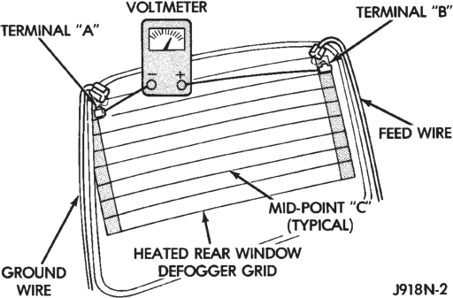
The above checks will confirm system operation. Illumination of the switch LED means that there is power available at the output of the defogger relay, but does not confirm that power is reaching the rear glass heating grid lines.
If the defogger system does not operate, the problem should be isolated in the following manner:
(1) Confirm that the ignition switch is in the On position.
(2) Ensure that the rear glass heating grid feed and ground wires are connected to the glass. Confirm that the ground wire has continuity to ground.
(3) Check the fuses in the power distribution center and in the junction block. The fuses must be tight in their receptacles and all electrical connections must be secure.
When the above steps have been completed and the rear glass heating grid is still inoperative, one or more of the following is faulty:
• Defogger switch • Defogger relay • Body control module • Rear window grid lines (all grid lines would have to be broken or one of the feed wires disconnected for the entire system to be inoperative).
When the above steps have been completed and the heated mirror glass heating element is still inoperative, one or more of the following is faulty:
• Body control module • CCD data bus • Driver or passenger door module • Outside rear view mirror heating elements
If setting the defogger switch to the On position produces a severe voltmeter deflection, check for a short circuit between the defogger relay output and the rear glass heating grid.
REAR GLASS HEATING GRID
For circuit descriptions and diagrams, refer to 8W-48 - Rear Window Defogger in Group 8W - Wiring Diagrams. To detect breaks in the grid lines, the following procedure is required:
(1) Turn the ignition switch to the On position. Set the rear defogger switch in the On position. The indicator lamp should light. If OK, go to Step 2. If not OK, see the diagnosis for Defogger Relay in this group.
(2) Using a 12-volt DC voltmeter, contact the vertical bus bar on the passenger’s side of the vehicle with the negative lead. With the positive lead, contact the vertical bus bar on the driver’s side of the vehicle. The voltmeter should read battery voltage. If OK, go to Step 3. If not OK, repair the open circuit to the defogger relay as required.
(3) With the negative lead of the voltmeter, contact a good body ground point. The voltage reading should not change. If OK, go to Step 4. If not OK, repair the circuit to ground as required.
(4) Connect the negative lead of the voltmeter to the passenger’s side bus bar and touch each grid line at mid-point C with the positive lead. A reading of approximately six volts indicates a line is good. A reading of zero volts indicates a break in the grid line between mid-point C and the driver’s side bus bar. A reading of 10-14 volts indicates a break between mid-point C and the passenger’s side bus bar. Move the positive lead on the grid line towards the break and the voltage reading will change as soon as the break is crossed.
DEFOGGER SWITCH
For circuit descriptions and diagrams, refer to 8W-48 - Rear Window Defogger in Group 8W - Wiring Diagrams.
WARNING: ON VEHICLES EQUIPPED WITH AIR- BAGS, REFER TO GROUP 8M - PASSIVE RESTRAINT SYSTEMS BEFORE ATTEMPTING STEERING WHEEL, STEERING COLUMN, OR INSTRUMENT PANEL COMPONENT DIAGNOSIS OR SERVICE. FAILURE TO TAKE THE PROPER PRE- CAUTIONS COULD RESULT IN ACCIDENTAL AIR- BAG DEPLOYMENT AND POSSIBLE PERSONAL INJURY.
(1) Disconnect and isolate the battery negative cable. Remove the right instrument panel switch pod and unplug the switch pod 10-way wiring connector.
(2) Check for continuity between the ground circuit cavity of the switch pod 10-way wire harness connector and a good ground. There should be continuity. If OK, go to Step 3. If not OK, repair the open circuit as required.
(3) Using two jumper wires, connect the ground circuit terminal in the 10-way connector receptacle on the back of the switch pod housing to a good ground, connect the fused rear window defogger relay output circuit terminal of the 10-way connector receptacle to a 12-volt battery feed. The defogger switch LED should light. If OK, go to Step 4. If not OK, replace the faulty switch pod.
(4) Check for continuity between the ground circuit and rear window defogger switch sense circuit terminals of the 10-way connector receptacle on the back of the switch pod housing. There should be continuity with the defogger switch button depressed, and no continuity with the switch button released. If OK, go to Step 5. If not OK, replace the faulty switch pod.
(5) Unplug the white 24-way connector from the body control module. Check for continuity between the rear window defogger switch sense circuit cavity of the switch pod 10-way wire harness connector and a good ground. There should be no continuity. If OK, go to Step 6. If not OK, repair the short circuit as required.
(6) Check for continuity between the rear window defogger switch sense circuit cavities of the switch pod 10-way wire harness connector and the body control module white 24-way harness connector. There should be continuity. If OK, see the Defogger Relay diagnosis in this group. If not OK, repair the open circuit as required.
DEFOGGER RELAY
RELAY TEST
The defogger relay is located in the junction block, on the right cowl side panel below the instrument panel in the passenger compartment. Remove the defogger relay from the junction block as described in this group to perform the following tests:
(1) A relay in the de-energized position should have continuity between terminals 87A and 30, and no continuity between terminals 87 and 30. If OK, go to Step 2. If not OK, replace the faulty relay.
(2) Resistance between terminals 85 and 86 (electromagnet) should be 75610 ohms. If OK, go to Step 3. If not OK, replace the faulty relay. (3) Connect a battery to terminals 85 and 86. There should now be continuity between terminals 30 and 87, and no continuity between terminals 87A and 30. If OK, see the Relay Circuit Test in this group. If not OK, replace the faulty relay.
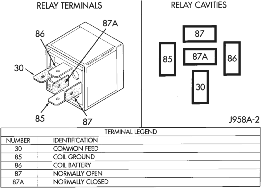
Defogger Relay
RELAY CIRCUIT TEST
(1) The relay common feed terminal cavity (30) is connected to battery voltage and should be hot at all times. If OK, go to Step 2. If not OK, repair the open circuit to the PDC fuse as required.
(2) The relay normally closed terminal (87A) is connected to terminal 30 in the de-energized position, but is not used for this application. Go to Step 3.
(3) The relay normally open terminal (87) is connected to the common feed terminal (30) in the energized position. This terminal supplies battery voltage to the fuse in the junction block that feeds the rear glass heating grid and the defogger switch LED. There should be continuity between the cavity for relay terminal 87 and the rear glass heating grid/defogger switch LED at all times. If OK, go to Step 4. If not OK, check the fuse in the junction block and/or repair the open circuit as required.
(4) The coil battery terminal (86) is connected to the electromagnet in the relay. It is connected to battery voltage and should be hot at all times. Check for battery voltage at the cavity for relay terminal 86. If OK, go to Step 5. If not OK, repair the open circuit to the PDC fuse as required.
(5) The coil ground terminal (85) is connected to the electromagnet in the relay. This terminal is provided with ground by the Body Control Module (BCM) to energize the rear glass heating grid and defogger switch LED. There should be continuity to the rear window defogger relay control circuit cavity of the white 24-way BCM connector. If OK, use a DRB scan tool and the proper Body Diagnostic Procedures Manual to diagnose the BCM. If not OK, repair the open circuit as required.
SERVICE PROCEDURES
REAR GLASS HEATING GRID REPAIRS
Repair of the grid lines, bus bars or pigtail wires can be accomplished using a Mopar Rear Window Defogger Repair Kit (P/N 4267922) or equivalent.
WARNING: MATERIALS CONTAINED IN THE REPAIR KIT MAY CAUSE SKIN OR EYE IRRITATION. THE KIT CONTAINS EPOXY RESIN AND AMINE TYPE HARDENER, WHICH ARE HARMFUL IF SWAL- LOWED. AVOID CONTACT WITH THE SKIN AND EYES. FOR SKIN CONTACT, WASH THE AFFECTED AREAS WITH SOAP AND WATER. FOR CONTACT WITH THE EYES, FLUSH WITH PLENTY OF WATER. DO NOT TAKE INTERNALLY. IF TAKEN INTER- NALLY, INDUCE VOMITING AND CALL A PHYSICIAN IMMEDIATELY. USE WITH ADEQUATE VENTILA- TION. DO NOT USE NEAR FIRE OR FLAME. CON- TAINS FLAMMABLE SOLVENTS. KEEP OUT OF THE REACH OF CHILDREN.
(1) Mask the repair area so that the conductive epoxy can be applied neatly. Extend the epoxy application onto the grid line or the bus bar on either side of the break (Fig. 2).
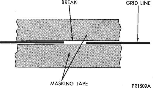
(2) Follow the instructions in the repair kit for preparing the damaged area.
(3) Remove the package separator clamp and mix the two conductive epoxy components thoroughly within the packaging. Fold the package in half and cut the center corner to dispense the epoxy.
(4) For grid line repairs, mask the area to be repaired with masking tape or a template.
(5) Apply the epoxy through the slit in the masking tape or template. Overlap both ends of the break by at least 19 mm (0.75 in.).
(6) For a terminal or pigtail replacement, mask the adjacent areas so the epoxy can be extended onto the adjacent grid line as well as the bus bar. Apply a thin layer of epoxy to the area where the terminal or pigtail was fastened and onto the adjacent grid line.
(7) Apply a thin layer of conductive epoxy to the terminal or bare wire end of the pigtail and place in the desired location. To prevent the terminal or pigtail from moving while the epoxy is curing, it must be wedged or clamped.
(8) Carefully remove the masking tape or template.
CAUTION: Do not allow the glass surface to exceed 204°C (400°F) or the glass may fracture.
(9) Allow the epoxy to cure 24 hours at room temperature, or use a heat gun with a 260°-371°C (500°- 700°F) range for 15 minutes. Hold the heat gun approximately 254 mm (10 in.) from the repair.
(10) After the conductive epoxy is properly cured, remove the wedge or clamp from the terminal or pigtail. Do not attach the connectors until the curing process is complete.
(11) Check the operation of the rear window defogger.
REMOVAL AND INSTALLATION
DEFOGGER SWITCH
WARNING: ON VEHICLES EQUIPPED WITH AIR- BAGS, REFER TO GROUP 8M - PASSIVE RESTRAINT SYSTEMS BEFORE ATTEMPTING STEERING WHEEL, STEERING COLUMN, OR INSTRUMENT PANEL COMPONENT DIAGNOSIS OR SERVICE. FAILURE TO TAKE THE PROPER PRE- CAUTIONS COULD RESULT IN ACCIDENTAL AIR- BAG DEPLOYMENT AND POSSIBLE PERSONAL INJURY.
(1) Disconnect and isolate the battery negative cable.
(2) Using a trim stick or other suitable wide flatbladed tool, pry gently around the edges of the right switch pod bezel and remove the bezel.
(3) Remove the three screws securing the right switch pod to the instrument panel (Fig. 3).
(4) Pull the right switch pod out from the instrument panel far enough to unplug the wiring connectors.
(5) Remove the right switch pod from the instrument panel.
(6) Reverse the removal procedures to install.
DEFOGGER RELAY
WARNING: ON VEHICLES EQUIPPED WITH AIR- BAGS, REFER TO GROUP 8M - PASSIVE RESTRAINT SYSTEMS BEFORE ATTEMPTING STEERING WHEEL, STEERING COLUMN, OR INSTRUMENT PANEL COMPONENT DIAGNOSIS OR SERVICE. FAILURE TO TAKE THE PROPER PRE- CAUTIONS COULD RESULT IN ACCIDENTAL AIR- BAG DEPLOYMENT AND POSSIBLE PERSONAL INJURY.
(1) Disconnect and isolate the battery negative cable.
(2) Remove the fuse access panel by unsnapping it from the right cowl side trim panel.
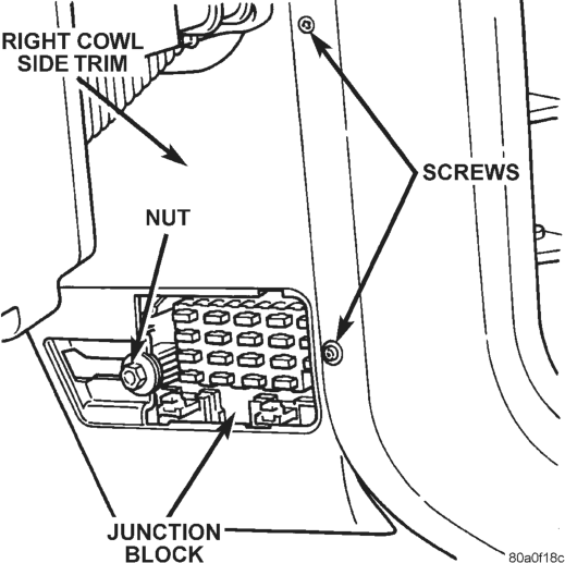
(3) Remove the nut securing the right cowl side trim to the junction block stud (Fig. 4).
(4) Remove the two screws securing the right cowl side trim to the right front door opening trim.
(5) Remove the right cowl side trim panel. (6) Unplug the defogger relay from the junction block.
(7) To install the relay, align the terminals with the cavities in the junction block and push the relay firmly into place.
(8) Connect the battery negative cable. (9) Test the defogger relay operation. (10) Install the right cowl side trim panel and the fuse access panel.
HEATED SEATS
INDEX
GENERAL INFORMATION
INTRODUCTION . . . . . . . . . . . . . . . . . . . . . . . . . 7 DESCRIPTION AND OPERATION
HEATED SEAT CONTROL MODULE . . . . . . . . . . . 7 HEATED SEAT ELEMENTS AND SENSOR . . . . . . 8 HEATED SEAT SWITCH . . . . . . . . . . . . . . . . . . . . 7 DIAGNOSIS AND TESTING
HEATED SEAT CONTROL MODULE . . . . . . . . . . . 9
GENERAL INFORMATION
INTRODUCTION
Individually controlled electrically heated front seats are available factory-installed optional equipment on this model. The seat heaters will only operate when the ignition switch is in the On position, and the surface temperature at the front seat heating element sensors is below the system’s designed temperature set points. The heated seat system will not operate in ambient temperatures greater than about 32°C (90°F). There are separate three-position switches for each front seat located in the right instrument panel switch pod, just right of the steering column. An Off, Low, or High position can be selected with each switch, and Light-Emitting Diodes (LED) for each switch illuminate to give a visual indication that the system is turned on. The Low heat position set point is about 32°C (90°F), and the High heat position set point is about 38°C (100°F). Each switch controls a Heated Seat Control Module (HSCM) mounted to the seat cushion frame under each front seat.
When a seat heater is turned on, a sensor located near the seat cushion electric heater element provides the HSCM with an input indicating the surface temperature of the seat cushion. If the surface temperature input is below the temperature set point for the selected Low or High switch position, a relay in the HSCM energizes the heating elements in the seat cushion and back. When the sensor input indicates the correct temperature set point has been achieved, the HSCM de-energizes the relay. The HSCM will continue to cycle the relay as needed to maintain the temperature set point.
The HSCM will automatically disconnect power from the heating elements if it detects an open in the sensor circuit, or a short in the heating element circuit causing an excessive current draw. The system is also turned off automatically when the ignition page page
HEATED SEAT ELEMENT . . . . . . . . . . . . . . . . . . 9 HEATED SEAT SENSOR . . . . . . . . . . . . . . . . . . . 9 HEATED SEAT SWITCH . . . . . . . . . . . . . . . . . . . . 8 HEATED SEAT SYSTEM . . . . . . . . . . . . . . . . . . . 8 REMOVAL AND INSTALLATION
HEATED SEAT CONTROL MODULE . . . . . . . . . . . 9 HEATED SEAT SWITCH . . . . . . . . . . . . . . . . . . . . 9 switch is turned to the Off position. The control circuit operates on ignition switched power from a fuse in the junction block. The heating elements operate on power supplied through the power seat circuit breaker in the junction block.
Following are general descriptions of the major components in the heated seat system. Refer to 8W-63 - Power Seat With Heated Seats in Group 8W - Wiring Diagrams for complete circuit descriptions and diagrams.
DESCRIPTION AND OPERATION
HEATED SEAT SWITCH
The heated seat switch is integral to the right switch pod, which is mounted in the instrument panel just right of the steering column. The two three-position sliding-type switches, one switch for each front seat, provide a resistor multiplexed signal to their respective Heated Seat Control Module (HSCM). Each switch has an Off, Low, and High position so that both the driver and the front seat passenger can select a preferred seat heating mode.
Each switch has a Light-Emitting Diode (LED), which lights to indicate that the heated seat that the switch controls is turned on. The heated seat switches and their LED cannot be repaired. If faulty, the right switch pod unit must be replaced.
HEATED SEAT CONTROL MODULE
The Heated Seat Control Module (HSCM) is an electronic thermostatic module designed to operate the electric seat heater elements. Two modules are used in the vehicle, one for each front seat. The HSCM for each seat is mounted to a bracket under the seat cushion spring. The bracket is fastened to the inside surface of the outboard seat cushion frame with a single screw driven through the frame from the outside.
Inputs to the module include the multiplex resistor instrument panel switch signals (which includes the seat cushion temperature sensor circuits), an ignition-switched battery feed, an unswitched battery feed, and a ground. The only HSCM output is the feed for the seat heating elements.
The HSCM cannot be repaired and, if faulty, must be replaced.
HEATED SEAT ELEMENTS AND SENSOR
Two heated seat heating elements are used in each front seat, one for the seat cushion and the other for the seat back. The two elements for each seat are connected in series with the HSCM.
The temperature sensor is a negative temperature coefficient thermistor. One temperature sensor is used for each seat, and it is integrated into the seat cushion heating element.
The heating elements are sewn into the seat cushion cover and seat back cover assemblies, which are serviced individually. The heating elements and temperature sensor cannot be repaired and, if faulty, the affected seat cover assembly must be replaced. Refer to Group 23 - Body Components for the seat cover service procedures.
DIAGNOSIS AND TESTING
HEATED SEAT SYSTEM
For circuit descriptions and diagrams, refer to 8W-63 - Power Seat With Heated Seats in Group 8W - Wiring Diagrams.
WARNING: ON VEHICLES EQUIPPED WITH AIR- BAGS, REFER TO GROUP 8M - PASSIVE RESTRAINT SYSTEMS BEFORE ATTEMPTING STEERING WHEEL, STEERING COLUMN, OR INSTRUMENT PANEL COMPONENT DIAGNOSIS OR SERVICE. FAILURE TO TAKE THE PROPER PRE- CAUTIONS COULD RESULT IN ACCIDENTAL AIR- BAG DEPLOYMENT AND POSSIBLE PERSONAL INJURY.
Before testing the individual components in the heated seat system check the following:
• If the heated seat switch LED doesn’t light with the ignition switch in the On position and the heated seat switch in Low or High, check the fuse in the junction block. If the fuse is OK, test the heated seat switch as described in this group.
• If the heated seat switch LED lights, but the heating elements don’t heat, check the circuit breaker in the junction block. If the circuit breaker is OK, test the heated seat elements as described in this group.
HEATED SEAT SWITCH
For circuit descriptions and diagrams, refer to 8W-63 - Power Seat With Heated Seats in Group 8W - Wiring Diagrams.
WARNING: ON VEHICLES EQUIPPED WITH AIR- BAGS, REFER TO GROUP 8M - PASSIVE RESTRAINT SYSTEMS BEFORE ATTEMPTING STEERING WHEEL, STEERING COLUMN, OR INSTRUMENT PANEL COMPONENT DIAGNOSIS OR SERVICE. FAILURE TO TAKE THE PROPER PRE- CAUTIONS COULD RESULT IN ACCIDENTAL AIR- BAG DEPLOYMENT AND POSSIBLE PERSONAL INJURY.
(1) Disconnect and isolate the battery negative cable. Remove the right switch pod as described in this group. Unplug the 10-way connector from the switch pod.
(2) Check for continuity between the ground circuit cavity of the 10-way switch pod connector and a good ground. There should be continuity. If OK, go to Step 3. If not OK, repair the open circuit as required.
(3) Connect the battery negative cable. Turn the ignition switch to the On position. Check for battery voltage at the fused ignition switch output circuit cavity of the 10-way switch pod connector. If OK, go to Step 4. If not OK, repair the open circuit as required.
(4) Turn the ignition switch to the Off position. Disconnect and isolate the battery negative cable. Remove the remaining switch pod connectors and remove the right switch pod from the instrument panel.
(5) With both heated seat switches in the Off position, check for continuity between the fused ignition switch output circuit and the driver heated seat switch output circuit terminals in the 10-way connector receptacle on the back of the right switch pod. Repeat this check between the fused ignition switch output circuit and the passenger heated seat switch output circuit terminals. In each case, there should be no continuity. If OK, go to Step 6. If not OK, replace the faulty right switch pod.
(6) Move both heated seat switches to the Low position. Using an ohmmeter, check the resistance between the fused ignition switch output circuit and the driver heated seat switch output circuit terminals in the 10-way connector receptacle on the back of the right switch pod. Repeat this check between the fused ignition switch output circuit and the passenger heated seat switch output circuit terminals. In each case, the resistance reading should be about 11.5 kilohms. If OK, go to Step 7. If not OK, replace the faulty right switch pod.
(7) Move both heated seat switches to the High position. Using an ohmmeter, check the resistance between the fused ignition switch output circuit and the driver heated seat switch output circuit terminals in the 10-way connector receptacle on the back of the right switch pod. Repeat this check between the fused ignition switch output circuit and the passenger heated seat switch output circuit terminals. In each case, the resistance reading should be about 6.5 kilohms. If not OK, replace the faulty right switch pod.
HEATED SEAT CONTROL MODULE
Before testing the heated seat control module, test the heated seat switch, the heated seat elements, and the heated seat sensor as described in this group. If testing of the heated seat switch, elements, and sensor reveals no problems, replace the heated seat control module with a known good unit and test the operation of the heated seats. If OK, discard the faulty heated seat control module. If not OK, test the circuits from the heated seat switch, elements, and sensor to the heated seat control module. Repair any short or open circuits as required. For circuit descriptions and diagrams, refer to 8W-63 - Power Seat With Heated Seats in Group 8W - Wiring Diagrams.
HEATED SEAT ELEMENT
The connectors for the seat cushion and seat back heating elements are located under the seat near the rear edge of the seat cushion frame. For circuit descriptions and diagrams, refer to 8W-63 - Power Seat With Heated Seats in Group 8W - Wiring Diagrams.
SEAT CUSHION
(1) Disconnect and isolate the battery negative cable. Unplug the 4-way heated seat cushion connector.
(2) Check for continuity between the two heated seat driver circuit cavities of the seat cover half of the heated seat cushion connector. There should be continuity. If OK, go to Step 3. If not OK, replace the faulty seat cushion cover.
(3) Check for continuity between one of the heated seat driver circuit cavities of the seat cover half of the heated seat cushion connector and the seat cushion frame. There should be no continuity. If OK, test the seat back element. If not OK, replace the faulty seat cushion cover.
SEAT BACK
(1) Disconnect and isolate the battery negative cable. Unplug the 2-way heated seat back connector.
(2) Check for continuity between the heated seat driver circuit cavity and the ground circuit cavity of the seat cover half of the heated seat back connector. There should be continuity. If OK, go to Step 3. If not OK, replace the faulty seat back cover.
(3) Check for continuity between the heated seat driver circuit cavity of the seat cover half of the heated seat back connector and the seat back frame. There should be no continuity. If OK, test the heated seat sensor as described in this group. If not OK, replace the faulty seat back cover.
HEATED SEAT SENSOR
The connector for the seat cushion heating element and sensor are located under the seat near the rear edge of the seat cushion frame. For circuit descriptions and diagrams, refer to 8W-63 - Power Seat With Heated Seats in Group 8W - Wiring Diagrams.
(1) Disconnect and isolate the battery negative cable. Unplug the 4-way heated seat cushion connector.
(2) Using an ohmmeter, check the resistance between the heated seat switch output circuit cavity and the ground circuit cavity of the seat cover half of the heated seat cushion connector. The sensor resistance should be between 2 kilohms and 200 kilohms. If OK, test the heated seat control module as described in this group. If not OK, replace the faulty seat cushion cover.
REMOVAL AND INSTALLATION
HEATED SEAT SWITCH
WARNING: ON VEHICLES EQUIPPED WITH AIR- BAGS, REFER TO GROUP 8M - PASSIVE RESTRAINT SYSTEMS BEFORE ATTEMPTING STEERING WHEEL, STEERING COLUMN, OR INSTRUMENT PANEL COMPONENT DIAGNOSIS OR SERVICE. FAILURE TO TAKE THE PROPER PRE- CAUTIONS COULD RESULT IN ACCIDENTAL AIR- BAG DEPLOYMENT AND POSSIBLE PERSONAL INJURY.
(1) Disconnect and isolate the battery negative cable.
(2) Using a trim stick or other suitable wide flatbladed tool, pry gently around the edges of the right switch pod bezel and remove the bezel.
(3) Remove the three screws securing the right switch pod to the instrument panel (Fig. 1).
(4) Pull the right switch pod out from the instrument panel far enough to unplug the wiring connectors.
(5) Remove the right switch pod from the instrument panel.
(6) Reverse the removal procedures to install.
HEATED SEAT CONTROL MODULE
(1) Move the power seat adjuster to its upper-most and forward-most stop positions.
(2) Remove the three screws securing the seat side shield to the seat cushion frame and pull the shield away from the seat so that the power recliner adjuster lower bracket can be seen.
(3) Adjust the seat back with the power recliner switch so that both of the two bolts in the power recliner adjuster lower bracket can be accessed.
(4) Disconnect and isolate the battery negative cable.
(5) Remove the two bolts securing the power recliner adjuster lower bracket to the seat cushion frame.
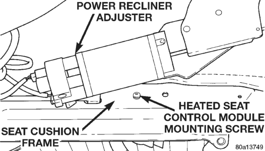
(6) Gently pry the power recliner adjuster lower bracket upwards to access the heated seat control module mounting screw (Fig. 2).
(7) Remove the mounting screw from the seat cushion frame.
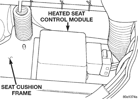
(8) Reach under the rear of the seat cushion to lower the heated seat control module and mounting bracket unit from the inside of the seat cushion frame (Fig. 3).
(9) Unplug the wiring connector and remove the module from under the seat.
(10) Reverse the removal procedures to install. Tighten the power recliner adjuster lower bracket bolts to 28 N·m (20 ft. lbs.).