Charging System — 1996 Jeep Grand Cherokee ZJ Service Manual
Pages 293–300 · 8 pages · 1 words repaired
electronic memory for any failure it detects. See On- Board Diagnostic System Test in this group for more information.
GENERATOR
The generator is belt-driven by the engine using a serpentine type drive belt. It is serviced only as a complete assembly. If the generator fails for any reason, the entire assembly must be replaced.
As the energized rotor begins to rotate within the generator, the spinning magnetic field induces a current into the windings of the stator coil. Once the generator begins producing sufficient current, it also provides the current needed to energize the rotor.
The Y type stator winding connections deliver the induced AC current to 3 positive and 3 negative diodes for rectification. From the diodes, rectified DC current is delivered to the vehicle electrical system through the generator battery and ground terminals.
Although the generators appear the same externally, different generators with different output ratings are used on this vehicle. This will depend upon engine size and optional equipment. Be certain that the replacement generator has the same output rating as the original unit. See Generator Ratings in the Specifications section at the back of this group for amperage ratings.
Noise emitting from the generator may be caused by: worn, loose or defective bearings; a loose or defective drive pulley; incorrect, worn, damaged or misadjusted fan drive belt; loose mounting bolts; a misaligned drive pulley or a defective stator or diode.
BATTERY TEMPERATURE SENSOR
The battery temperature sensor is used to determine the battery temperature and control battery charging rate. This temperature data, along with data from monitored line voltage, is used by the PCM to vary the battery charging rate. System voltage will be higher at colder temperatures and is gradually reduced at warmer temperatures.
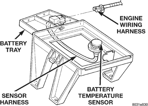
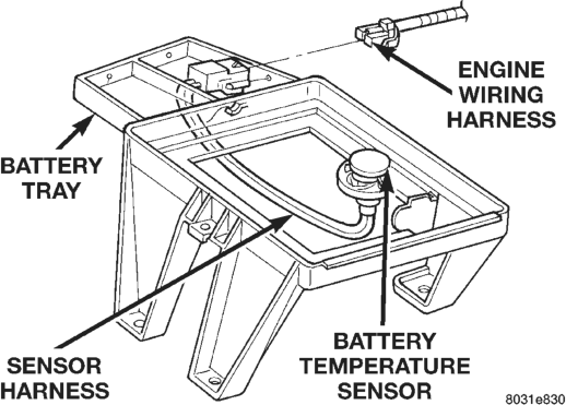
The sensor is located under the vehicle battery, and is attached to the battery tray (Fig. 1).
VOLTAGE REGULATOR
The Electronic Voltage Regulator (EVR) is not a separate component. It is actually a voltage regulating circuit located within the Powertrain Control Module (PCM). The EVR is not serviced separately. If replacement is necessary, the PCM must be replaced.
Operation: The amount of DC current produced by the generator is controlled by EVR circuitry contained within the PCM. This circuitry is connected in series with the generators second rotor field terminal and its ground.
Voltage is regulated by cycling the ground path to control the strength of the rotor magnetic field. The EVR circuitry monitors system line voltage and battery temperature (refer to Battery Temperature Sensor for more information). It then compensates and regulates generator current output accordingly. Also see Charging System Operation for additional information.
DIAGNOSIS AND TESTING
CHARGING SYSTEM
When the ignition switch is turned to the ON position, battery potential will register on the voltmeter. During engine cranking a lower voltage will appear on the meter. With the engine running, a voltage reading higher than the first reading (ignition in ON) should register.
The following procedures may be used to diagnose the charging system if:
• the voltmeter does not operate properly • an undercharged or overcharged battery condition occurs.
Remember that an undercharged battery is often caused by:
• accessories being left on with the engine not running
• a faulty or improperly adjusted switch that allows a lamp to stay on. See Ignition-Off Draw Test in Group 8A, Battery for more information.
INSPECTION
(1) Inspect condition of battery cable terminals, battery posts, connections at engine block, starter solenoid and relay. They should be clean and tight. Repair as required.
(2) Inspect all fuses in the fuseblock module and Power Distribution Center (PDC) for tightness in receptacles. They should be properly installed and tight. Repair or replace as required.
(3) Inspect the electrolyte level in the battery. Replace battery if electrolyte level is low.
(4) Inspect generator mounting bolts for tightness. Replace or tighten bolts if required. Refer to the Generator Removal/Installation section of this group for torque specifications.
(5) Inspect generator drive belt condition and tension. Tighten or replace belt as required. Refer to Belt Tension Specifications in Group 7, Cooling System.
(6) Inspect automatic belt tensioner (if equipped). Refer to Group 7, Cooling System for information.
(7) Inspect connections at generator field, battery output, and ground terminals. Also check ground connection at engine. They should all be clean and tight. Repair as required.
CHARGING SYSTEM RESISTANCE TESTS
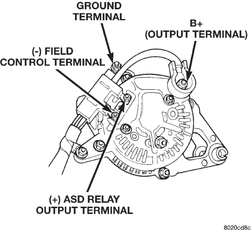
These tests will show the amount of voltage drop across the generator output wire, from the generator output (B+) terminal (Fig. 2) to the battery positive post. They will also show the amount of voltage drop from the ground (-) terminal on the generator (Fig. 2) to the battery negative post.
A voltmeter with a 0–18 volt DC scale should be used for these tests. By repositioning the voltmeter test leads, the point of high resistance (voltage drop) can easily be found.
PREPARATION
(1) Before starting test, make sure battery is in good condition and is fully-charged. See Group 8A, Battery for more information.
(2) Check condition of battery cables at battery. Clean if necessary.
(3) Start the engine and allow it to reach normal operating temperature.
(4) Shut engine off. (5) Connect an engine tachometer. (6) Fully engage the parking brake.
TEST
(1) Start engine. (2) Place heater blower in high position. (3) Turn on headlamps and place in high-beam position.
(4) Turn vehicle interior lamps on. (5) Start engine. Bring engine speed up to 2400 rpm and hold.
(6) Testing (+) circuitry:
(a) Touch the negative lead of voltmeter directly to battery positive post.
(b) Touch the positive lead of voltmeter to the B+ output terminal stud on the generator (not the terminal mounting nut). Voltage should be no higher than 0.6 volts. If voltage is higher than 0.6 volts, touch test lead to terminal mounting stud nut and then to the wiring connector. If voltage is now below 0.6 volts, look for dirty, loose or poor connection at this point. Also check condition of the generator output wire-tobattery bullet connector. Refer to Group 8, Wiring for connector location. A voltage drop test may be performed at each (+) connection in this circuit to locate the excessive resistance. (7) Testing (-) circuitry:
(a) Touch the negative lead of voltmeter directly to battery negative post.
(b) Touch the positive lead of voltmeter to the ground terminal stud on the generator case (not the terminal mounting nut). Voltage should be no higher than 0.3 volts. If voltage is higher than 0.3 volts, touch test lead to terminal mounting stud nut and then to the wiring connector. If voltage is now below 0.3 volts, look for dirty, loose or poor connection at this point. A voltage drop test may be performed at each (-) connection in this circuit to locate the excessive resistance. This test can also be performed between the generator case and the engine. If test voltage is higher than 0.3 volts, check for corrosion at generator mounting points or loose generator mounting.
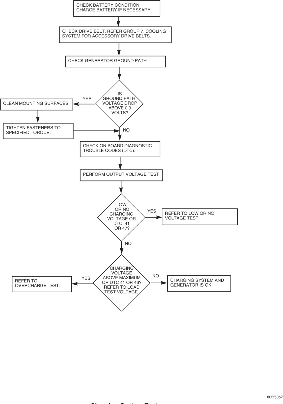
Charging System Test
CURRENT OUTPUT TEST
The current output test will determine if the charging system can deliver its minimum test current (amperage) output. Refer to the Specifications section at the end of this group for minimum test current (amperage) requirements.
The first part of this test (Test 1) will determine the combined amperage output of both the generator and the Electronic Voltage Regulator (EVR) circuitry. The second part of this test (Test 2) will determine only generator amperage and will not include analysis of EVR circuitry. EVR circuitry is located within the Powertrain Control Module (PCM). To test voltage regulator circuitry, refer to the appropriate Powertrain Diagnostic Procedures service manual.
PREPARATION
(1) Determine if any Diagnostic Trouble Codes (DTC’s) exist. To determine a DTC, refer to On-Board Diagnostics in this group. For repair, refer to the appropriate Powertrain Diagnostic Procedures manual.
(2) Before starting test, make sure battery is in good condition and is fully-charged. See Group 8A, Battery for more information.
(3) Check condition of battery cables at battery. Clean if necessary.
(4) Perform the previous Output Wire Resistance Test (voltage drop test). This will ensure clean and tight generator/battery electrical connections.
(5) Be sure the generator drive belt is properly tensioned. Refer to Group 7, Cooling System for information.
(6) A volt/amp tester equipped with both a battery load control (carbon pile rheostat) and an inductivetype pickup clamp (ammeter probe) will be used for this test. Refer to operating instructions supplied with tester. When using a tester equipped with an inductive-type clamp, removal of wiring at the generator will not be necessary.
(7) Start the engine and allow it to reach operating temperature.
(8) Shut engine off. (9) Turn off all electrical accessories and all vehicle lighting.
(10) Connect the volt/amp tester leads to the battery. Be sure the carbon pile rheostat control is in the OPEN or OFF position before connecting leads. See Load Test in Group 8A, Battery for more information. Also refer to the operating instructions supplied with test equipment.
(11) Connect the inductive clamp (ammeter probe). Refer to the operating instructions supplied with test equipment.
(12) If volt/amp tester is not equipped with an engine tachometer, connect a separate tachometer to the engine.
TEST 1
(1) Perform the previous test Preparation. (2) Fully engage the parking brake. (3) Start engine. (4) Bring engine speed to 2500 rpm. (5) With engine speed held at 2500 rpm, slowly adjust the rheostat control (load) on the tester to obtain the highest amperage reading. Do not allow voltage to drop below 12 volts. Record the reading. This load test must be performed within 15 seconds to prevent damage to test equipment. On certain brands of test equipment, this load will be applied automatically. Refer to the operating manual supplied with test equipment.
(6) The ammeter reading must meet the Minimum Test Amps specifications as displayed in the Generator Ratings chart. This can be found in the Specifications section at the end of this group. A label stating a part reference number is attached to the generator case. On some engines this label may be located on the bottom of the case. Compare this reference number to the Generator Ratings chart.
(7) Rotate the load control to the OFF position. (8) Continue holding engine speed at 2500. If EVR circuitry is OK, amperage should drop below 15–20 amps. With all electrical accessories and vehicle lighting off, this could take several minutes of engine operation. If amperage did not drop, refer to the appropriate Powertrain Diagnostic Procedures manual for testing.
(9) Remove volt/amp tester. If minimum amperage could not be met, proceed to Test 2. This test will determine if the generator is faulty, or if EVR circuitry is defective.
TEST 2
(1) Perform the previous test preparation. (2) Fully engage the parking brake. (3) Connect one end of a jumper wire to a good ground. Connect the other end of jumper wire to the (-) field control circuit terminal. This terminal is located on the back of the generator (Fig. 2). Connecting the jumper wire will remove the voltage regulator circuitry from the test. It will also generate a Diagnostic Trouble Code (DTC).
CAUTION: Do not connect the jumper wire to the (+) ASD Relay output terminal (Fig. 2). Damage to electrical system components may result. The (-) field control circuit terminal is located farther away from the B+ output terminal than the (+) ASD Relay terminal (Fig. 2).
(4) Start engine. Immediately after starting, reduce engine speed to idle. This will prevent any electrical accessory damage from high voltage.
(5) Adjust carbon pile rheostat (load) and engine speed in slow increments until a speed of 1250 rpm, and a voltmeter reading of 15 volts is obtained. Immediately record ammeter reading. Do not apply load to system longer than 15 seconds as damage to test equipment may result.
CAUTION: When adjusting rheostat load, do not allow voltage to rise above 16 volts. Damage to the battery and electrical system components may result.
(6) The ammeter reading must meet the Minimum Test Amps specifications as displayed in the Generator Ratings chart. This can be found in the Specifications section at the end of this group. A label stating a part reference number is attached to the generator case. On some engines this label may be located on the bottom of the case. Compare this reference number to the Generator Rating chart.
(7) Remove volt/amp tester. (8) Remove jumper wire. (9) Use the DRB scan tool to erase the DTC. Refer to the DRB screen for procedures.
RESULTS
• If amp reading meets specifications in Test 2, generator is OK.
• If amp reading is less than specified in Test 2, and wire resistance (voltage drop) tests were OK, the generator should be replaced. Refer to Removal and Installation in this group for procedures.
• If Test 2 results were OK, but Test 1 results were not, the problem is in EVR circuitry. Refer to appropriate Powertrain Diagnostic Procedures manual for diagnosis.
BATTERY TEMPERATURE SENSOR To perform a complete test of this sensor and its circuitry, refer to the appropriate Powertrain Diagnostic Procedures manual. To test the sensor only, refer to the following:
(1) The sensor is located under the battery and is attached to the battery tray (Fig. 1). A two-wire pigtail harness is attached directly to the sensor. The opposite end of this harness connects the sensor to the engine wiring harness.
(2) Disconnect the two-wire pigtail harness from the engine harness.
(3) Attach ohmmeter leads to the wire terminals of the pigtail harness.
(4) At room temperature of 25° C (75–80° F), an ohmmeter reading of 9 to 11K ohms should be observed.
(5) If reading is above or below the specification, replace the sensor.
(6) Refer to the Removal and Installation section for procedures.
ON-BOARD DIAGNOSTIC SYSTEM TEST
GENERAL INFORMATION
The Powertrain Control Module (PCM) monitors critical input and output circuits of the charging system, making sure they are operational. A Diagnostic Trouble Code (DTC) is assigned to each input and output circuit monitored by the OBD system. Some circuits are checked continuously and some are checked only under certain conditions.
If the OBD system senses that a monitored circuit is bad, it will put a DTC into electronic memory. The DTC will stay in electronic memory as long as the circuit continues to be bad. The PCM is programmed to clear the memory after 50 engine starts if the problem does not occur again.
DIAGNOSTIC TROUBLE CODES
Diagnostic Trouble Codes (DTC) are two-digit numbers flashed on the malfunction indicator (Check Engine) lamp that identify which circuit is bad. Refer to Group 25, On Board Diagnostic for more information. A DTC description can also be read using the DRB scan tool. Refer to the appropriate Powertrain Diagnostic Procedures manual for information.
A DTC does not identify which component in a circuit is bad. Thus, a DTC should be treated as a symptom, not as the cause for the problem. In some cases, because of the design of the diagnostic test procedure, a DTC can be the reason for another DTC to be set. Therefore, it is important that the test procedures be followed in sequence, to understand what caused a DTC to be set.
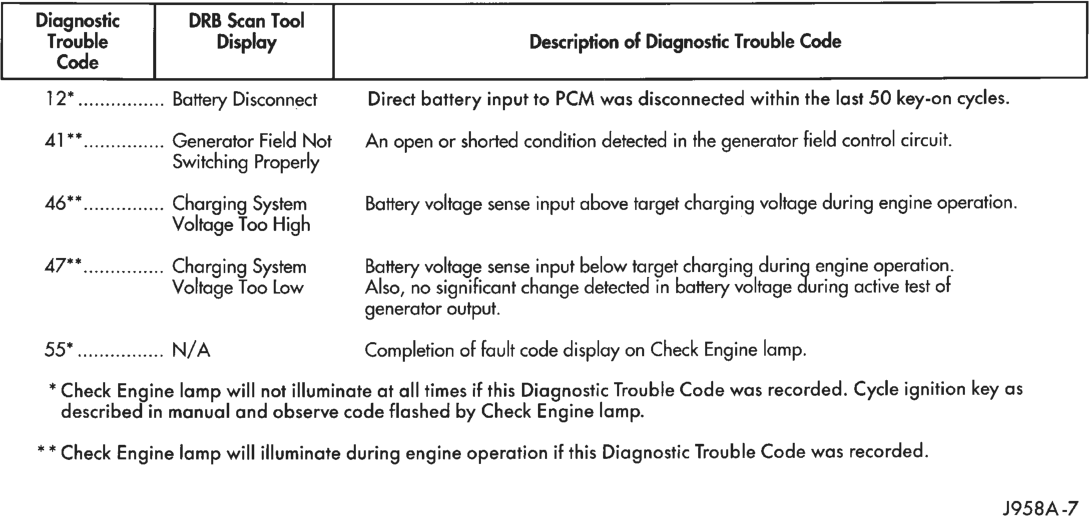
See the Generator Diagnostic Trouble Code chart (Fig. 3) for DTC’s which apply to the charging system. Refer to the Powertrain Diagnostic Procedures manual to diagnose an on-board diagnostic system trouble code.
RETRIEVING DIAGNOSTIC TROUBLE CODES
To start this function, cycle the ignition switch ON- OFF-ON-OFF-ON within 5 seconds. This will cause any DTC stored in the PCM memory to be displayed. The malfunction indicator (Check Engine) lamp will display a DTC by flashing on and off. There is a short pause between flashes and a longer pause between digits. All DTC’s displayed are two-digit numbers, with a four-second pause between codes.
An example of a DTC is as follows: (1) Lamp on for 2 seconds, then turns off. (2) Lamp flashes 4 times pauses and then flashes 1 time. (3) Lamp pauses for 4 seconds, flashes 4 times, pauses, then flashes 7 times.
(4) The two DTC’s are 41 and 47. Any number of DTC’s can be displayed, as long as they are in memory. The lamp will flash until all stored DTC’s are displayed, then it will flash a DTC 55 to indicate the test is complete.
Fig. 3 Generator Diagnostic Trouble Code
ERASING DIAGNOSTIC TROUBLE CODES
The DRB Scan Tool must be used to erase a DTC.
REMOVAL AND INSTALLATION
GENERATOR
WARNING: DISCONNECT NEGATIVE CABLE FROM BATTERY BEFORE REMOVING BATTERY OUTPUT WIRE FROM GENERATOR. FAILURE TO DO SO CAN RESULT IN INJURY.
(1) Disconnect negative battery cable. (2) Remove generator drive belt. Refer to Group 7, Cooling System for procedure.
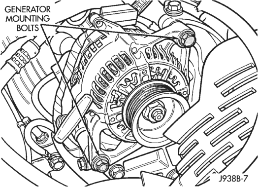
(3) Remove the generator pivot and mounting bolts (Fig. 4). Position generator for access to wire connectors. (4) Remove nuts from harness holddown, battery terminal, ground terminal and 2 field terminals (Fig. 5). Remove wire connectors. (5) Remove the generator. (6) Reverse removal procedures to install. Tighten generator hardware as follows:
• Generator mounting bolt 5.2L engines - 41 N·m (30 ft. lbs.)
• Generator pivot bolt 5.2L engines - 41 N·m (30 ft. lbs.)
• Generator mounting bolt 4.0L engine - 55 N·m (41 ft. lbs.)
• Generator pivot bolt 4.0L engine - 55 N·m (41 ft. lbs.) • Battery terminal nut - 8.5 N·m (75 in. lbs.) • Ground terminal nut - 8.5 N·m (75 in. lbs.) • Harness holddown nut - 8.5 N·m (75 in. lbs.)
Trouble Display Description of Diagnostic Trouble Code
Code
127 sees Battery Disconnect Direct battery input to PCM was disconnected within the last 50 key-on cycles.
Generator Field Not An open or shorted condition detected in the generator field control circuit.
Switching Properly
A6** Charging System Battery voltage sense input above target charging voltage during engine operation.
Voltage Too High
AT Charging System Battery voltage sense input below target charging during engine operation.
Voltage Too Low Also, no significant change detected in battery voltage during active test of
generator output.
55” eee N/A Completion of fault code display on Check Engine lamp.
* Check Engine lamp will not illuminate at all times if this Diagnostic Trouble Code was recorded. Cycle ignition key as
described in manual and observe code flashed by Check Engine lamp.
** Check Engine lamp will illuminate during engine operation if this Diagnostic Trouble Code was recorded.
J958A -7
• Field terminal nuts - 2.8 N·m (25 in. lbs.)
CAUTION: Never force a belt over a pulley rim using a screwdriver. The synthetic fiber of the belt can be damaged.
CAUTION: When installing a serpentine accessory drive belt, the belt MUST be routed correctly. The water pump will be rotating in the wrong direction if the belt is installed incorrectly, causing the engine to overheat. Refer to belt routing label in engine compartment, or refer to Belt Schematics in Group 7, Cooling System.
Typical
BATTERY TEMPERATURE SENSOR
The battery temperature sensor is located under vehicle battery (Fig. 6) and is attached to a mounting hole on battery tray. REMOVAL
(1) Remove the battery. Refer to Group 8A, Battery for procedures.
SPECIFICATIONS
GENERATOR RATINGS
TYPE PART NUMBER RATED SAE AMPS ENGINES MINIMUM TEST
DENSO 56005685 117 4.0L 90
DENSO 56005686 136 4.0L 120
DENSO 56027912 117 5.2L 90
DENSO 56027913 136 5.2L 120
TORQUE SPECIFICATIONS
Description Torque Generator Mounting Bolt—
5.2L Engine. . . . . . . . . . . . . . . .41 N·m (30 ft. lbs.) Generator Pivot Bolt—
5.2L Engine. . . . . . . . . . . . . . . .41 N·m (30 ft. lbs.) Generator Mounting Bolt—
4.0L Engine. . . . . . . . . . . . . . . .55 N·m (41 ft. lbs.)
(2) Disconnect the sensor pigtail harness from the engine wire harness.
(3) Pry the sensor straight up from the battery tray mounting hole.
INSTALLATION
(1) Feed the pigtail harness through the hole in top of battery tray and press sensor into top of battery tray.
(2) Connect the pigtail harness. (3) Install the battery. Refer to Group 8A, Battery for procedures.
AMPS
Description Torque Generator Pivot Bolt—
4.0L Engine. . . . . . . . . . . . . . . .55 N·m (41 ft. lbs.) Battery Terminal Nut . . . . . . . . .8.5 N·m (75 in. lbs.) Ground Terminal Nut . . . . . . . . .8.5 N·m (75 in. lbs.) Harness Hold-down Nut . . . . . . .8.5 N·m (75 in. lbs.) Field Terminal Nuts . . . . . . . . . .2.8 N·m (25 in. lbs.)