Battery — 1996 Jeep Grand Cherokee ZJ Service Manual
Pages 272–284 · 13 pages · 7 words repaired
condition. See Built-In Test Indicator in this group for more information.
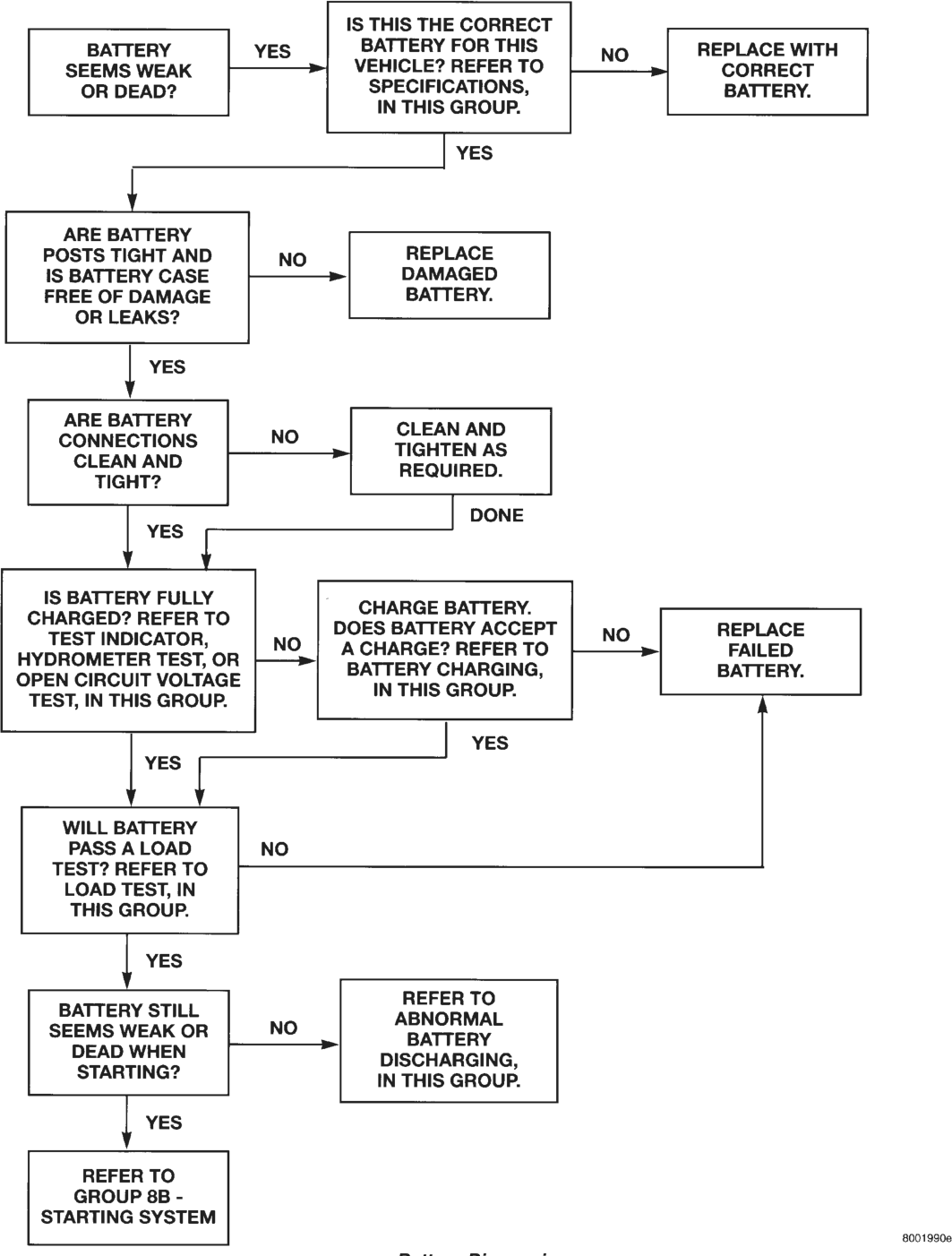
It is important that the battery, starting, and charging systems be thoroughly tested and inspected any time a battery needs to be charged or replaced. The cause of abnormal discharge, over-charging, or early battery failure must be diagnosed and corrected before a battery is replaced or returned to service.
DESCRIPTION AND OPERATION
BATTERY
The storage battery is a device used to store electrical energy potential in a chemical form. When an electrical load is applied to the battery terminals, an electrochemical reaction occurs within the battery. This reaction causes the battery to discharge electrical current.
The battery is made up of six individual cells that are connected in series. Each cell contains positively charged plate groups made of lead oxide, and negatively charged plate groups made of sponge lead. These dissimilar metal plates are submerged in a sulfuric acid and water solution called an electrolyte.
As the battery discharges, a gradual chemical change takes place within each cell. The sulfuric acid in the electrolyte combines with the plate materials, causing both plates to slowly change to lead sulfate. At the same time, oxygen from the positive plate material combines with hydrogen from the sulfuric acid, causing the electrolyte to become mainly water.
The chemical changes within the battery are caused by the movement of excess, or free, electrons between the positive and negative plate groups. This movement of electrons produces a flow of electrical current through the load device attached to the battery terminals.
As the plate materials become more similar chemically, and the electrolyte becomes less acid, the voltage potential of each cell is reduced. However, by charging the battery with a voltage higher than that of the battery, the battery discharging process is reversed.
Charging the battery gradually changes the sulfated lead plates back into sponge lead and lead oxide, and the water back into sulfuric acid. This action restores the difference in the electron charges deposited on the plates, and the voltage potential of the battery cells.
For a battery to remain useful, it must be able to produce high-amperage current over an extended period. A battery must also be able to accept a charge, so that its voltage potential may be restored.
In addition to producing and storing electrical energy, the battery serves as a capacitor, or voltage stabilizer, for a vehicle’s electrical system. It absorbs most abnormal or transient voltages caused by the switching of any of the vehicle’s electrical components.
The battery is vented to release excess hydrogen gas that is created when the battery is being charged or discharged. However, even with these vents, the hydrogen gas can collect in or around the battery. If hydrogen gas is exposed to flame or sparks, it may ignite.
If the electrolyte level is low, the battery may arc internally and explode. If the battery is equipped with removable cell caps, add distilled water whenever the electrolyte level is below the top of the plates. If the battery cell caps cannot be removed, the battery must be replaced if the electrolyte level becomes low.
BATTERY SIZE AND RATINGS
The outside dimensions and terminal placement of the battery conform to standards established by the Battery Council International (BCI). Each battery is assigned a BCI Group Size number to help identify a correctly-sized replacement.
In addition, there are two commonly accepted methods for rating and comparing battery performance. These ratings are called Cold Cranking Amperage (CCA) and Reserve Capacity (RC). Both ratings are described in more detail below.
The Group Size number, CCA rating, and RC rating can be found on the original equipment battery label. Be certain that a replacement battery has the correct Group Size number, as well as CCA and RC ratings that equal or exceed the original equipment specification for the vehicle being serviced. See the Battery Classifications and Ratings chart in Specifications at the back of this group for more information.
COLD CRANKING AMPERAGE
The Cold Cranking Amperage (CCA) rating specifies how much current (in amperes) the battery can deliver for 30 seconds at -17.7°C (0°F). Terminal voltage must not fall below 7.2 volts during or after the 30 second discharge. The CCA required is generally higher as engine displacement increases, depending also upon the starter current draw requirements.
RESERVE CAPACITY
The Reserve Capacity (RC) rating specifies the time (in minutes) it takes for battery terminal voltage to fall below 10.2 volts, at a discharge rate of 25 amperes. RC is determined with the battery fullycharged at 26.7°C (80°F). This rating estimates how long the battery might last after a charging system failure, under minimum electrical load.
BATTERY MOUNTING
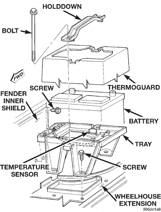
The battery is mounted to a molded plastic tray located in the right front corner of the engine compartment. Two U-nuts are held in formations on each side of the tray. A holddown strap fits across the top of the battery case and thermoguard. A bolt passes through the holddown strap on each side of the battery, and is threaded into the U-nut on each side of the battery tray.
The battery tray is fastened with three screws to the front wheelhouse extension panel, forward of the right front wheel. The tray is also secured to the right fender inner shield with two screws.
A vacuum reservoir for the vehicle speed control and heater-A/C systems is mounted to the underside of the battery tray. Refer to Group 8H - Vehicle Speed Control System and Group 24 - Heating and Air Conditioning for more information on the vacuum reservoir.
A hole in the bottom of the battery tray is fitted with a battery temperature sensor on some models. Models without the battery temperature sensor have a plug fitted to this hole. Refer to Group 8C - Charging System for more information on the battery temperature sensor.
DIAGNOSIS AND TESTING
BATTERY
The battery must be completely charged and the top, posts, and terminal clamps should be properly cleaned before diagnostic procedures are performed. See Battery Charging in this group for more information.
WARNING:
IF THE BATTERY SHOWS SIGNS OF FREEZING, LEAKING, LOOSE POSTS, OR LOW ELECTROLYTE LEVEL, DO NOT TEST, ASSIST-BOOST, OR CHARGE. THE BATTERY MAY ARC INTERNALLY AND EXPLODE. PERSONAL INJURY AND/OR VEHI- CLE DAMAGE MAY RESULT.
EXPLOSIVE HYDROGEN GAS FORMS IN AND AROUND THE BATTERY. DO NOT SMOKE, USE FLAME, OR CREATE SPARKS NEAR THE BATTERY. PERSONAL INJURY AND/OR VEHICLE DAMAGE MAY RESULT.
THE BATTERY CONTAINS SULFURIC ACID, WHICH IS POISONOUS AND CAUSTIC. AVOID CON- TACT WITH THE SKIN, EYES, OR CLOTHING. IN THE EVENT OF CONTACT, FLUSH WITH WATER AND CALL A PHYSICIAN IMMEDIATELY. KEEP OUT OF THE REACH OF CHILDREN.
IF THE BATTERY IS EQUIPPED WITH REMOV- ABLE CELL CAPS, BE CERTAIN THAT EACH OF THE CELL CAPS IS IN PLACE AND TIGHT BEFORE
THE BATTERY IS RETURNED TO SERVICE. PER- SONAL INJURY AND/OR VEHICLE DAMAGE MAY RESULT FROM LOOSE OR MISSING CELL CAPS.
The condition of a battery is determined by two criteria:
1. State-Of-Charge - This can be determined by viewing the built-in test indicator, by checking the specific gravity of the electrolyte (hydrometer test), or by checking the battery voltage (open-circuit voltage test).
2. Cranking Capacity - This can be determined by performing a battery load test, which measures the ability of the battery to supply high-amperage current.
First, determine the battery state-of-charge. This can be done in one of three ways. If the battery has a built-in test indicator, use this test to determine the state-of-charge. If the battery has no test indicator, but has removable cell caps, perform the hydrometer test to determine the state-of-charge. If the cell caps are not removable, or a hydrometer is not available, perform the open-circuit voltage test to determine the state-of-charge.
The battery must be charged before proceeding with a load test if:
• The built-in test indicator has a black or dark color visible.
• The temperature corrected specific gravity is less than 1.235.
• The open-circuit voltage is less than 12.4 volts. A battery that will not accept a charge is faulty, and must be replaced. Further testing is not required. A fully-charged battery must be load tested to determine its cranking capacity. A battery that is fully-charged, but does not pass the load test, is faulty and must be replaced.
NOTE: Completely discharged batteries may take several hours to accept a charge. See Charging A Completely Discharged Battery in this group for more information.
A battery is fully-charged when: • All cells are gassing freely during charging. • A green color is visible in the sight glass of the built-in test indicator.
• Three corrected specific gravity tests, taken at 1-hour intervals, indicate no increase in the specific gravity.
• Open-circuit voltage is 12.4 volts or greater.
ABNORMAL BATTERY DISCHARGING
Any of the following conditions can result in abnormal battery discharging:
1. Corroded or loose battery posts and terminal clamps.
Battery Diagnosis
2. A loose or worn generator drive belt. 3. Electrical loads that exceed the output of the charging system. This can be due to equipment installed after manufacture, or repeated short trip use.
4. Slow driving speeds (heavy traffic conditions) or prolonged idling, with high-amperage draw systems in use.
5. A faulty circuit or component causing excessive ignition-off draw. See Ignition-Off Draw Test in this group for more information.
6. A faulty or incorrect charging system component.
7. A faulty or incorrect battery.
BUILT-IN TEST INDICATOR
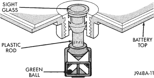
A test indicator (hydrometer) built into the top of the battery case provides visual information for battery testing (Fig. 2). Like a hydrometer, the built-in test indicator measures the specific gravity of the electrolyte. The test indicator reveals the battery state-of-charge; however, it will not reveal the cranking capacity of the battery. A load test must be performed to determine the battery cranking capacity. See Load Test in this group for more information.
WARNING:
IF THE BATTERY SHOWS SIGNS OF FREEZING, LEAKING, LOOSE POSTS, OR LOW ELECTROLYTE LEVEL, DO NOT TEST, ASSIST-BOOST, OR CHARGE. THE BATTERY MAY ARC INTERNALLY AND EXPLODE. PERSONAL INJURY AND/OR VEHI- CLE DAMAGE MAY RESULT.
EXPLOSIVE HYDROGEN GAS FORMS IN AND AROUND THE BATTERY. DO NOT SMOKE, USE FLAME, OR CREATE SPARKS NEAR THE BATTERY. PERSONAL INJURY AND/OR VEHICLE DAMAGE MAY RESULT.
THE BATTERY CONTAINS SULFURIC ACID, WHICH IS POISONOUS AND CAUSTIC. AVOID CON- TACT WITH THE SKIN, EYES, OR CLOTHING. IN THE EVENT OF CONTACT, FLUSH WITH WATER AND CALL A PHYSICIAN IMMEDIATELY. KEEP OUT OF THE REACH OF CHILDREN.
IF THE BATTERY IS EQUIPPED WITH REMOV- ABLE CELL CAPS, BE CERTAIN THAT EACH OF THE CELL CAPS IS IN PLACE AND TIGHT BEFORE THE BATTERY IS RETURNED TO SERVICE. PER- SONAL INJURY AND/OR VEHICLE DAMAGE MAY RESULT FROM LOOSE OR MISSING CELL CAPS.
Before testing, visually inspect the battery for any damage (a cracked case or cover, loose posts, etc.) that would cause the battery to be faulty. In order to obtain correct indications from the built-in test indicator, it is important that the battery be level and have a clean sight glass. Additional light may be required to view the indicator. Do not use open flame as a source of additional light.
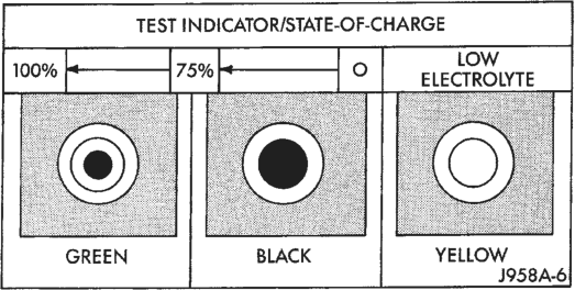
To read the built-in test indicator, look into the sight glass and note the color of the indicator (Fig. 3). Refer to the following description, as the color indicates:
• Green - indicates 75% to 100% state-of-charge. The battery is adequately charged for further testing or return to use. If the vehicle will not crank for a minimum of 15 seconds with a fully-charged battery, perform the Load Test.
• Black or Dark - indicates 0% to 75% state-ofcharge. The battery is inadequately charged and must be charged until a green indication is visible in the sight glass (12.4 volts or more), before the battery is tested further or returned to service. See Battery Charging in this group for more information. Also see Abnormal Battery Discharging in this group for possible causes of the discharged condition.
• Yellow or Bright - indicates a low electrolyte level. The electrolyte level in the battery is below the test indicator. A maintenance-free battery with nonremovable cell caps must be replaced if the electrolyte level is low. Water must be added to a lowmaintenance battery with removable cell caps before it is charged. See Battery Charging in this group for more information. A low electrolyte level may be caused by an over-charging condition. Refer to Group 8C - Charging System to diagnose an over-charging condition.
HYDROMETER TEST
The hydrometer test reveals the battery state-ofcharge by measuring the specific gravity of the electrolyte. This test cannot be performed on maintenance-free batteries with non-removable cell caps. If the battery has non-removable cell caps, see Built-In Test Indicator or Open Circuit Voltage Test in this group.
Specific gravity is a comparison of the density of the electrolyte to the density of pure water. Pure water has a specific gravity of 1.000, and sulfuric acid has a specific gravity of 1.835. Sulfuric acid makes up approximately 35% of the electrolyte by weight, or 24% by volume.
In a fully-charged battery the electrolyte will have a temperature-corrected specific gravity of 1.260 to 1.290. However, a specific gravity of 1.235 or above is satisfactory for battery load testing and/or return to service.
WARNING:
IF THE BATTERY SHOWS SIGNS OF FREEZING, LEAKING, LOOSE POSTS, OR LOW ELECTROLYTE LEVEL, DO NOT TEST, ASSIST-BOOST, OR CHARGE. THE BATTERY MAY ARC INTERNALLY AND EXPLODE. PERSONAL INJURY AND/OR VEHI- CLE DAMAGE MAY RESULT.
EXPLOSIVE HYDROGEN GAS FORMS IN AND AROUND THE BATTERY. DO NOT SMOKE, USE FLAME, OR CREATE SPARKS NEAR THE BATTERY. PERSONAL INJURY AND/OR VEHICLE DAMAGE MAY RESULT.
THE BATTERY CONTAINS SULFURIC ACID, WHICH IS POISONOUS AND CAUSTIC. AVOID CON- TACT WITH THE SKIN, EYES, OR CLOTHING. IN THE EVENT OF CONTACT, FLUSH WITH WATER AND CALL A PHYSICIAN IMMEDIATELY. KEEP OUT OF THE REACH OF CHILDREN.
IF THE BATTERY IS EQUIPPED WITH REMOV- ABLE CELL CAPS, BE CERTAIN THAT EACH OF THE CELL CAPS IS IN PLACE AND TIGHT BEFORE THE BATTERY IS RETURNED TO SERVICE. PER- SONAL INJURY AND/OR VEHICLE DAMAGE MAY RESULT FROM LOOSE OR MISSING CELL CAPS.
Before testing, visually inspect the battery for any damage (a cracked case or cover, loose posts, etc.) that would cause the battery to be faulty. Then remove the cell caps and check the electrolyte level. Add distilled water if the electrolyte level is below the top of the battery plates.
Refer to the hydrometer manufacturer’s instructions for correct use of the hydrometer. Remove only enough electrolyte from the battery so that the float is off the bottom of the hydrometer barrel with pressure on the bulb released.
CAUTION: Exercise care when inserting the tip of the hydrometer into a cell to avoid damaging the plate separators. Damaged plate separators can cause early battery failure.
To read the hydrometer correctly, hold it with the top surface of the electrolyte at eye level. Hydrometer floats are generally calibrated to indicate the specific gravity correctly only at 26.7°C (80°F). When testing the specific gravity at any other temperature, a correction factor is required.
The correction factor is approximately a specific gravity value of 0.004, referred to as 4 points of specific gravity. For each 5.5°C above 26.7°C (10°F above 80°F), add 4 points. For each 5.5°C below 26.7°C (10°F below 80°F), subtract 4 points. Always correct the specific gravity for temperature variation. Test the specific gravity of the electrolyte in each battery cell.
EXAMPLE: A battery is tested at -12.2°C (10°F) and has a specific gravity of 1.240. Determine the actual specific gravity as follows:
(1) Determine the number of degrees above or below 26.7°C (80°F): 26.6°C - -12.2°C = 38.8°C (80°F - 10°F = 70°F) (2) Divide the result from Step 1 by 5.5 (10): 38.8°C/5.5 = 7 (70°F/10 = 7) (3) Multiply the result from Step 2 by the temperature correction factor (0.004): 7 X 0.004 = 0.028 (4) The temperature at testing was below 26.7°C (80°F); therefore, the temperature correction factor is subtracted: 1.240 - 0.028 = 1.212 The corrected specific gravity of the battery in this example is 1.212.
If the specific gravity of all cells is above 1.235, but the variation between cells is more than 50 points (0.050), the battery should be replaced. If the specific gravity of one or more cells is less than 1.235, charge the battery at a rate of approximately 5 amperes.
Continue charging until three consecutive specific gravity tests, taken at 1-hour intervals, are constant. If the cell specific gravity variation is more than 50 points (0.050) at the end of the charge period, replace the battery.
When the specific gravity of all cells is above 1.235, and the cell variation is less than 50 points (0.050), the battery may be load tested to determine its cranking capacity. See Load Test in this group for more information.
OPEN-CIRCUIT VOLTAGE TEST
A battery open-circuit voltage (no load) test will show the state-of-charge of a battery. This test can be used in place of the hydrometer test, if a hydrometer is not available; or, for maintenance-free batteries with non-removable cell caps.
WARNING:
IF THE BATTERY SHOWS SIGNS OF FREEZING, LEAKING, LOOSE POSTS, OR LOW ELECTROLYTE LEVEL, DO NOT TEST, ASSIST-BOOST, OR CHARGE. THE BATTERY MAY ARC INTERNALLY AND EXPLODE. PERSONAL INJURY AND/OR VEHI- CLE DAMAGE MAY RESULT.
EXPLOSIVE HYDROGEN GAS FORMS IN AND AROUND THE BATTERY. DO NOT SMOKE, USE FLAME, OR CREATE SPARKS NEAR THE BATTERY. PERSONAL INJURY AND/OR VEHICLE DAMAGE MAY RESULT.
THE BATTERY CONTAINS SULFURIC ACID, WHICH IS POISONOUS AND CAUSTIC. AVOID CON- TACT WITH THE SKIN, EYES, OR CLOTHING. IN THE EVENT OF CONTACT, FLUSH WITH WATER AND CALL A PHYSICIAN IMMEDIATELY. KEEP OUT OF THE REACH OF CHILDREN.
IF THE BATTERY IS EQUIPPED WITH REMOV- ABLE CELL CAPS, BE CERTAIN THAT EACH OF THE CELL CAPS IS IN PLACE AND TIGHT BEFORE THE BATTERY IS RETURNED TO SERVICE. PER- SONAL INJURY AND/OR VEHICLE DAMAGE MAY RESULT FROM LOOSE OR MISSING CELL CAPS.
Before proceeding with this test, completely charge the battery as described in Battery Charging in this group.
(1) Before measuring the open-circuit voltage, the surface charge must be removed from the battery. Turn the headlamps on for 15 seconds, then allow up to five minutes for the battery voltage to stabilize.
(2) Disconnect and isolate both battery cables, negative cable first.
(3) Using a voltmeter connected to the battery posts (refer to the instructions provided with the voltmeter), measure the open-circuit voltage (Fig. 4).
See the Open-Circuit Voltage chart. This voltage reading will indicate the battery state-of-charge, but will not reveal its cranking capacity. If a battery has an open-circuit voltage reading of 12.4 volts or greater, it may be load tested to reveal its cranking capacity. See Load Test in this group for more information.
Open Circuit Voltage
Open Circuit Volts Charge Percentage
11.7 volts or less 0%
12.0 volts 25%
12.2 volts 50%
12.4 volts 75%
12.6 volts or more 100%
LOAD TEST
A battery load test will verify the battery cranking capacity. The test is based on the Cold Cranking Amperage (CCA) rating of the battery. See the Battery Classifications and Ratings chart in Specifications at the back of this group.
WARNING:
IF THE BATTERY SHOWS SIGNS OF FREEZING, LEAKING, LOOSE POSTS, OR LOW ELECTROLYTE LEVEL, DO NOT TEST, ASSIST-BOOST, OR CHARGE. THE BATTERY MAY ARC INTERNALLY AND EXPLODE. PERSONAL INJURY AND/OR VEHI- CLE DAMAGE MAY RESULT.
EXPLOSIVE HYDROGEN GAS FORMS IN AND AROUND THE BATTERY. DO NOT SMOKE, USE FLAME, OR CREATE SPARKS NEAR THE BATTERY. PERSONAL INJURY AND/OR VEHICLE DAMAGE MAY RESULT.
THE BATTERY CONTAINS SULFURIC ACID, WHICH IS POISONOUS AND CAUSTIC. AVOID CON- TACT WITH THE SKIN, EYES, OR CLOTHING. IN THE EVENT OF CONTACT, FLUSH WITH WATER AND CALL A PHYSICIAN IMMEDIATELY. KEEP OUT OF THE REACH OF CHILDREN.
IF THE BATTERY IS EQUIPPED WITH REMOV- ABLE CELL CAPS, BE CERTAIN THAT EACH OF THE CELL CAPS IS IN PLACE AND TIGHT BEFORE THE BATTERY IS RETURNED TO SERVICE. PER- SONAL INJURY AND/OR VEHICLE DAMAGE MAY RESULT FROM LOOSE OR MISSING CELL CAPS.
Before proceeding with this test, completely charge the battery as described in Battery Charging in this group.
(1) Disconnect and isolate both battery cables, negative cable first. The battery top and posts should be clean.
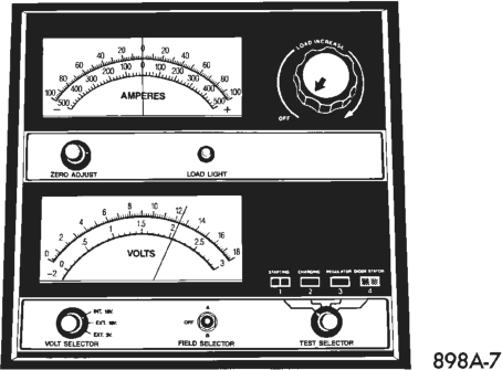
(2) Connect a suitable volt-ammeter-load tester (Fig. 5) to the battery posts (Fig. 6). Refer to the operating instructions provided with the tester being used. Check the open-circuit voltage (no load) of the battery. Open-circuit voltage must be 12.4 volts or greater.
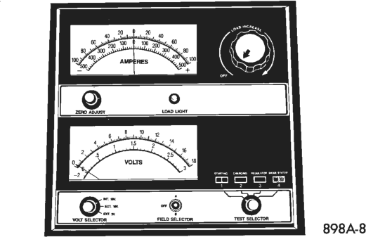

(3) Rotate the load control knob (carbon pile rheostat) to apply a 300 ampere load to the battery for 15 seconds, then return the control knob to the Off position (Fig. 7). This will remove the surface charge from the battery.
(4) Allow the battery to stabilize to open-circuit voltage. It may take up to five minutes for the battery voltage to stabilize.
(5) Rotate the load control knob to maintain a load equal to 50% of the battery’s CCA rating (Fig. 8). After 15 seconds, record the loaded voltage reading, then return the load control knob to the Off position.
(6) The voltage drop will vary with the battery temperature at the time of the load test. The battery temperature can be estimated by using the ambient temperature during the past several hours. If the battery has been charged, boosted, or loaded a few minutes prior to the test, the battery will be some-
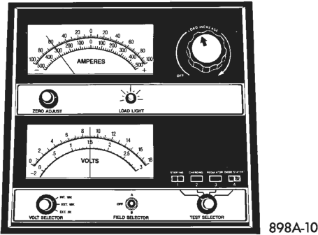
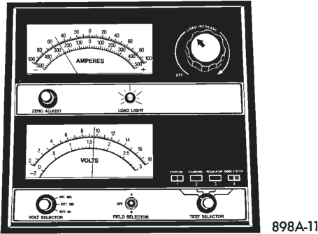
what warmer. See the Load Test Temperature chart for the proper loaded voltage reading.
Load Test Temperature
Temperature
Minimum Voltage
°F °C
9.6 volts 70° and above 21° and above
9.5 volts 60° 16°
9.4 volts 50° 10°
9.3 volts 40° 4°
9.1 volts 30° -1°
8.9 volts 20° -7°
8.7 volts 10° -12°
8.5 volts 0° -18°
(7) If the voltmeter reading falls below 9.6 volts, at a minimum battery temperature of 21°C (70°F), the battery is faulty and must be replaced.
IGNITION-OFF DRAW TEST
Ignition-Off Draw (IOD) refers to power being drained from the battery with the ignition switch in the Off position. A normal vehicle electrical system will draw from 5 to 25 milliamperes (0.005 - 0.025 ampere) with the ignition switch in the Off position, and all non-ignition controlled circuits in proper working order. The 25 milliamperes are needed to supply Powertrain Control Module (PCM) memory, digital clock memory, and electronically tuned radio memory.
A vehicle that has not been operated for approximately 20 days, may discharge the battery to an inadequate level. When a vehicle will not be used for 20 days or more (stored), remove the IOD fuse from the Power Distribution Center (PDC). This will reduce battery discharging.
Excessive IOD can be caused by: • Electrical items left on • Faulty or improperly adjusted switches • An internally shorted generator • Intermittent shorts in the wiring. If the IOD is over 25 milliamperes, the problem must be found and corrected before replacing a battery. In most cases, the battery can be charged and returned to service.
DIAGNOSIS
CAUTION: Testing for high-amperage IOD must be performed first to prevent damage to most milliampere meters.
(1) Verify that all electrical accessories are off. Turn off all lamps, remove the ignition key, and close all doors. If the vehicle is equipped with a illuminated entry system or electronically tuned radio, allow the electronic timer function of these systems to automatically shut off (time out). This may take up to three minutes.
(2) Determine that the underhood lamp is operating properly, then disconnect the lamp or remove the bulb.
(3) Disconnect the battery negative cable. (4) Connect a typical 12-volt test lamp (low-wattage bulb) between the disconnected battery negative cable clamp and the battery negative terminal post. Make sure that the doors remain closed so that the illuminated entry system is not activated. The test lamp may light brightly for up to three minutes, or may not light at all, depending upon the vehicle’s electrical equipment. The term “brightly,” as used throughout the following tests, implies the brightness of the test lamp will be the same as if it were connected across the battery. The test lamp must be securely clamped to the battery negative cable clamp and the battery negative terminal post. If the continuity between the battery negative terminal post and cable clamp is lost during any part of the IOD test, the electronic timer function will be activated and all tests must be repeated.
(5) After three minutes, the test lamp should turn off or be dimly lit, depending upon the vehicle’s electrical equipment. If the test lamp remains brightly lit, do not disconnect it. Remove each fuse or circuit breaker (refer to Group 8W - Wiring Diagrams for more information) until the test lamp is either off, or dimly lit. This will isolate each circuit and identify the source of the high-amperage IOD. If the test lamp is still brightly lit after disconnecting each fuse and circuit breaker, disconnect the wiring harness from the generator. If the test lamp now turns off or is dimly lit, refer to Group 8C - Charging System to diagnose the faulty charging system. Do not disconnect the test lamp. After the high-amperage IOD has been corrected, the low-amperage IOD may be checked. It is now safe to install a milliampere meter to check the low-amperage IOD.
(6) With the test lamp still connected securely, clamp a milliampere meter between the battery negative terminal post and the negative cable clamp.
CAUTION: Do not open any doors, or turn on any electrical accessories, with the test lamp disconnected or the milliampere meter may be damaged.
(7) Disconnect the test lamp. Observe the milliampere meter. The current draw should not exceed 25 milliamperes (0.025 ampere). If the draw exceeds 25 milliamperes, isolate each circuit by removing the circuit breakers and fuses. The milliampere meter reading will drop when the source of the draw is disconnected. Repair this circuit as required, whether it is a wiring short, incorrect switch adjustment or a component failure.
SERVICE PROCEDURES
BATTERY CHARGING
A battery is fully-charged when: • All cells are gassing freely during battery charging.
• A green color is visible in the sight glass of the built-in test indicator.
• Three corrected specific gravity tests, taken at 1-hour intervals, indicate no increase in the specific gravity.
• Open-circuit voltage is 12.4 volts or above.
WARNING:
IF THE BATTERY SHOWS SIGNS OF FREEZING, LEAKING, LOOSE POSTS, OR LOW ELECTROLYTE LEVEL, DO NOT TEST, ASSIST-BOOST, OR CHARGE. THE BATTERY MAY ARC INTERNALLY AND EXPLODE. PERSONAL INJURY AND/OR VEHI- CLE DAMAGE MAY RESULT.
EXPLOSIVE HYDROGEN GAS FORMS IN AND AROUND THE BATTERY. DO NOT SMOKE, USE FLAME, OR CREATE SPARKS NEAR THE BATTERY. PERSONAL INJURY AND/OR VEHICLE DAMAGE MAY RESULT.
THE BATTERY CONTAINS SULFURIC ACID, WHICH IS POISONOUS AND CAUSTIC. AVOID CON- TACT WITH THE SKIN, EYES, OR CLOTHING. IN THE EVENT OF CONTACT, FLUSH WITH WATER AND CALL A PHYSICIAN IMMEDIATELY. KEEP OUT OF THE REACH OF CHILDREN.
IF THE BATTERY IS EQUIPPED WITH REMOV- ABLE CELL CAPS, BE CERTAIN THAT EACH OF THE CELL CAPS IS IN PLACE AND TIGHT BEFORE THE BATTERY IS RETURNED TO SERVICE. PER- SONAL INJURY AND/OR VEHICLE DAMAGE MAY RESULT FROM LOOSE OR MISSING CELL CAPS.
CAUTION:
Always disconnect and isolate the battery negative cable before charging a battery. Do not exceed 16.0 volts while charging a battery. Damage to the vehicle electrical system components may result.
Battery electrolyte will bubble inside the battery case during normal battery charging. Electrolyte boiling or being discharged from the battery vents indicates a battery over-charging condition. Immediately reduce the charging rate or turn off the charger to evaluate the battery condition. Damage to the battery may result from over-charging.
The battery should not be hot to the touch. If the battery feels hot to the touch, turn off the charger and let the battery cool before continuing the charging operation. Damage to the battery may result.
Some battery chargers are equipped with polaritysensing circuitry. This circuitry protects the charger and/or battery from being damaged if they are improperly connected. If the battery state-of-charge is too low for the polarity-sensing circuitry to detect, the charger will not operate. This makes it appear that the battery will not accept charging current. Refer to the instructions provided with the battery charger to bypass the polarity-sensing circuitry.
After the battery has been charged to 12.4 volts or greater, perform a load test to determine the battery cranking capacity. If the battery will endure a load test, return the battery to use. If the battery will not endure a load test, it is faulty and must be replaced.
Clean and inspect the battery holddowns, tray, terminals, posts, and top before completing service. See the Battery Removal and Installation procedures in this group for more information.
CHARGING A COMPLETELY DISCHARGED BATTERY
The following procedure should be used to recharge a completely discharged battery. Unless this procedure is properly followed, a good battery may be needlessly replaced.
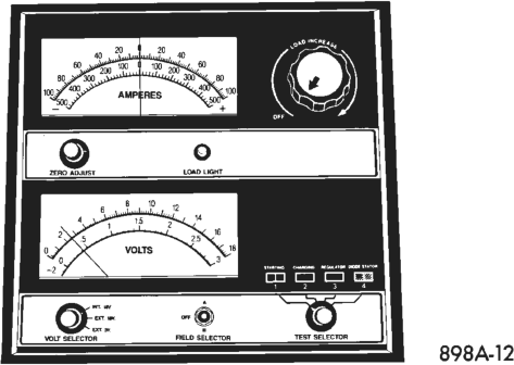
(1) Measure the voltage at the battery posts with a voltmeter, accurate to 1/10 (0.10) volt (Fig. 9). If the reading is below 10 volts, the charge current will be low. It could take some time before the battery accepts a current greater than a few milliamperes. Such low current may not be detectable on the ammeters built into many chargers.
(2) Disconnect and isolate the battery negative cable. Connect the battery charger leads. Some battery chargers are equipped with polarity-sensing circuitry. This circuitry protects the charger and/or battery from being damaged if they are improperly connected. If the battery state-of-charge is too low for the polarity-sensing circuitry to detect, the charger will not operate. This makes it appear that the battery will not accept charging current. Refer to the instructions provided with the battery charger to bypass the polarity-sensing circuitry.
(3) Battery chargers vary in the amount of voltage and current they provide. The amount of time required for a battery to accept measurable charger current at various voltages is shown in the Charge Rate chart. If the charge current is still not measurable at the end of the charging time, the battery is faulty and must be replaced. If the charge current is measurable during the charging time, the battery may be good and the charging should be completed in the normal manner.
Charge Rate
Voltage Hours
16.0 volts maximum up to 4 hours
14.0 to 15.9 volts up to 8 hours
13.9 volts or less up to 16 hours
CHARGING TIME REQUIRED
The time required to charge a battery will vary, depending upon the following factors:
• Battery Capacity - A completely discharged heavy-duty battery requires twice the charging time of a small capacity battery.
• Temperature - A longer time will be needed to charge a battery at -18°C (0°F) than at 27°C (80°F). When a fast charger is connected to a cold battery, the current accepted by the battery will be very low at first. As the battery warms, it will accept a higher charging current rate (amperage).
• Charger Capacity - A charger that supplies only 5 amperes will require a longer charging time. A charger that supplies 20 amperes or more will require a shorter charging time.
• State-Of-Charge - A completely discharged battery requires more charging time than a partially discharged battery. Electrolyte is nearly pure water in a completely discharged battery. At first, the charging current (amperage) will be low. As the battery charges, the specific gravity of the electrolyte will gradually rise.
WARNING: NEVER EXCEED 20 AMPERES WHEN CHARGING A COLD (-1°C/30°F) BATTERY. THE BAT- TERY MAY ARC INTERNALLY AND EXPLODE. PER- SONAL INJURY AND/OR VEHICLE DAMAGE MAY RESULT.
Battery Charging Timetable
Charging Amperage
5 Amperes
10 Amperes
20 Amperes
Open Circuit
Voltage Hours Charging at 21°C (70°F)
12.25 to 12.39 6 hours 3 hours 1.5 hours
12.00 to 12.24 8 hours 4 hours 2 hours
11.95 to 11.99 12 hours 6 hours 3 hours
10.00 to 11.94 14 hours 7 hours 3.5 hours less than 10.00 See Charging Completely
Discharged Battery
REMOVAL AND INSTALLATION
BATTERY
(1) Turn the ignition switch to the Off position. Make sure all electrical accessories are off.
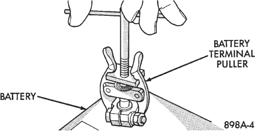
(2) Loosen the cable terminal clamps and disconnect both battery cables, negative cable first. If necessary, use a puller to remove the terminal clamps from the battery posts (Fig. 10).
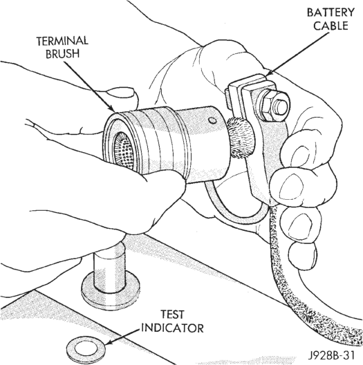
(3) Inspect the cable terminal clamps for corrosion and damage. Remove any corrosion using a wire brush or a post and terminal cleaning tool, and a sodium bicarbonate (baking soda) and warm water cleaning solution (Fig. 11). Replace any cable that has damaged or deformed terminal clamps.
WARNING: WEAR A SUITABLE PAIR OF RUBBER GLOVES (NOT THE HOUSEHOLD TYPE) WHEN REMOVING A BATTERY BY HAND. SAFETY GLASSES SHOULD ALSO BE WORN. IF THE BAT- TERY IS CRACKED OR LEAKING, THE ELECTRO- LYTE CAN BURN THE SKIN AND EYES.
(4) Remove the battery holddowns and remove the battery from the vehicle (Fig. 12).
(5) Inspect the battery tray and holddowns for corrosion or damage. Remove any corrosion using a wire brush and a sodium bicarbonate (baking soda) and warm water cleaning solution. Paint any exposed bare metal and replace any damaged parts.
(6) Inspect the battery case for cracks or other damage that could result in electrolyte leaks. Also, check the battery terminal posts for looseness. Batteries with damaged cases or loose posts must be replaced.
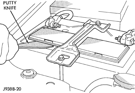
(7) Check the electrolyte level in the battery. Use a putty knife or another suitable wide flat-bladed tool to pry the cell caps off (Fig. 13). Do not use a screwdriver. Add distilled water to each cell until the liquid reaches the bottom of the vent well. DO NOT OVERFILL.
(8) Inspect the battery built-in test indicator sight glass for an indication of the battery condition. If the
battery is discharged, charge as required. See Built-In Test Indicator and Battery Charging in this group for more information.
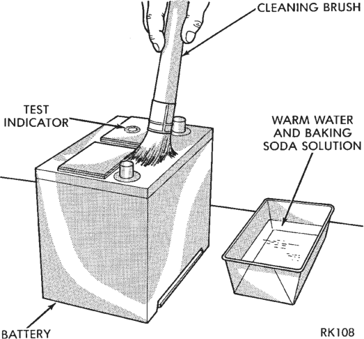
(9) If the battery is to be reinstalled, clean the outside of the battery case and the top cover with a sodium bicarbonate (baking soda) and warm water cleaning solution to remove any acid film (Fig. 14). Rinse the battery with clean water. Ensure that the cleaning solution does not enter the battery cells through the vent holes. If the battery is being replaced, see the Battery Ratings and Classifications chart in Specifications at the back of this group. Confirm that the replacement battery is the correct size and has the correct ratings for the vehicle.
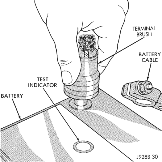
(10) Clean any corrosion from the battery terminal posts with a wire brush or a post and terminal cleaner, and a sodium bicarbonate (baking soda) and warm water cleaning solution (Fig. 15).
(11) Position the battery in the tray. Ensure that the positive and negative terminal posts are correctly positioned. The cable terminal clamps must reach the correct battery post without stretching the cables (Fig. 16).
(12) Loosely install the battery holddown hardware. Ensure that the battery base is correctly positioned in the tray, then tighten the holddowns to 2.2 N·m (20 in. lbs.).
CAUTION: Be certain that the battery cables are connected to the correct battery terminals. Reverse polarity may damage electrical components.
(13) Place an oiled felt washer on the battery positive terminal post.
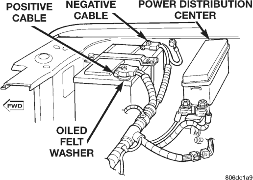
(14) Install and tighten the battery positive cable terminal clamp. Then install and tighten the negative cable terminal clamp. Tighten both cable terminal clamp bolts to 8.5 N·m (75 in. lbs.).
(15) Apply a thin coating of petroleum jelly or chassis grease to the exposed surfaces of the cable terminal clamps and battery terminal posts.
SPECIFICATIONS
BATTERY
Battery Classifications and Ratings
BCI Group
Cold Cranking Amperage
Reserve Capacity
Load Test Amperage
Size Classification
34 600 120 Minutes
300